Page 216 of 526
The light also will turn on when the parking brake is
applied with the ignition switch in the ON position.
NOTE:This light shows only that the parking brake is
applied. It does not show the degree of brake application.
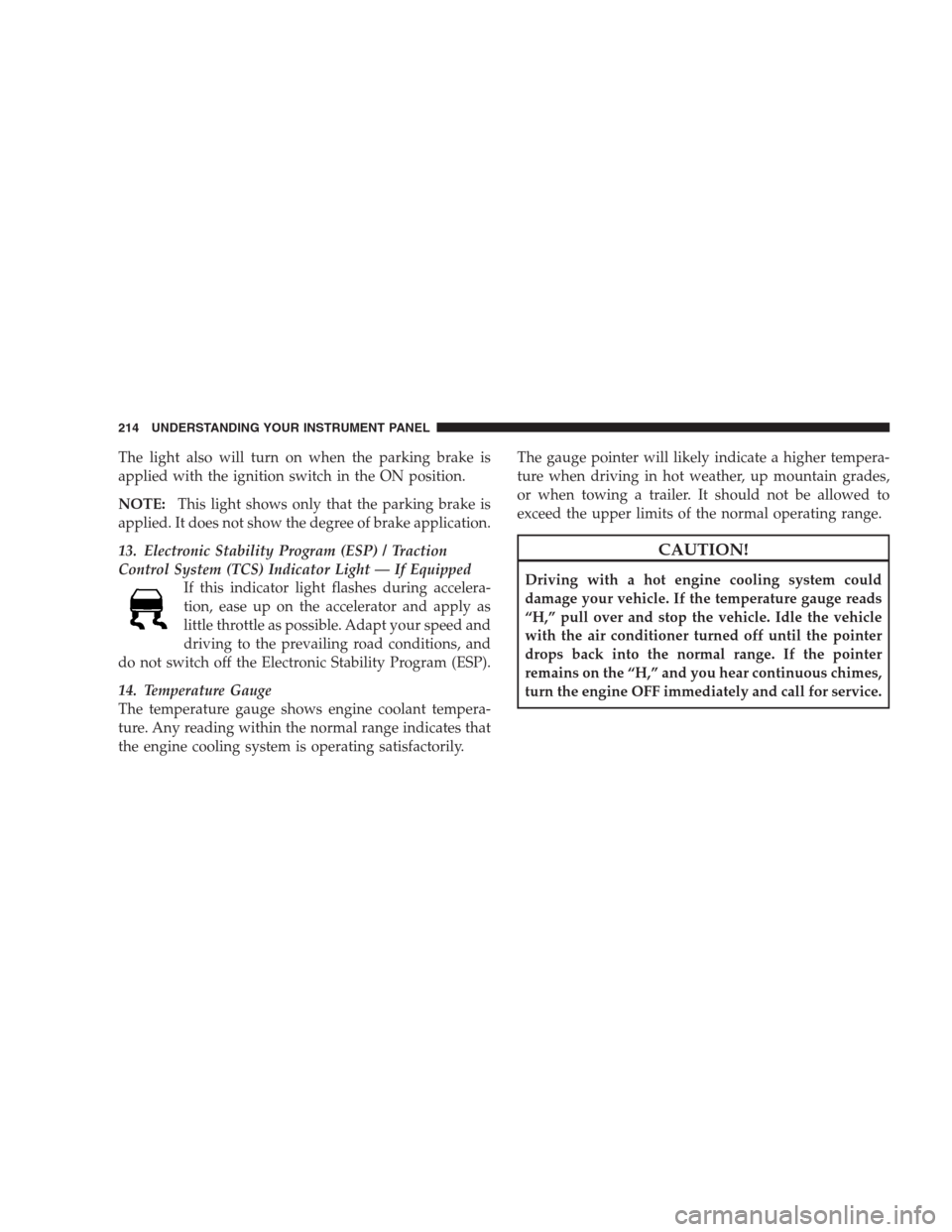
13. Electronic Stability Program (ESP) / Traction
Control System (TCS) Indicator Light — If Equipped
If this indicator light flashes during accelera-
tion, ease up on the accelerator and apply as
little throttle as possible. Adapt your speed and
driving to the prevailing road conditions, and
do not switch off the Electronic Stability Program (ESP).
14. Temperature Gauge
The temperature gauge shows engine coolant tempera-
ture. Any reading within the normal range indicates that
the engine cooling system is operating satisfactorily.The gauge pointer will likely indicate a higher tempera-
ture when driving in hot weather, up mountain grades,
or when towing a trailer. It should not be allowed to
exceed the upper limits of the normal operating range.
CAUTION!
Driving with a hot engine cooling system could
damage your vehicle. If the temperature gauge reads
“H,” pull over and stop the vehicle. Idle the vehicle
with the air conditioner turned off until the pointer
drops back into the normal range. If the pointer
remains on the “H,” and you hear continuous chimes,
turn the engine OFF immediately and call for service.
214 UNDERSTANDING YOUR INSTRUMENT PANEL
Page 218 of 526

18. Seat Belt Reminder Light
This light will turn on for five to eight seconds as
a bulb check when the ignition switch is first
turned ON. A chime will sound if the driver’s seat
belt is unbuckled during the bulb check. The Seat Belt
Reminder Light will flash or remain on continuously if
the driver’s seat belt remains unbuckled after the bulb
check or when driving.
19. Vehicle Security Light — If Equipped
The Vehicle Security Light flashes rapidly
when the Vehicle Security Alarm is arming,
and slowly when the Vehicle Security Alarm is
armed.
20. Fuel Gauge
The pointer shows the level of fuel in the fuel tank when
the ignition switch is in the ON position.21. Electronic Throttle Control (ETC) Light
This light will turn on briefly as a bulb check
when the ignition switch is turned ON. This
light will also turn on while the engine is
running if there is a problem with the Elec-
tronic Throttle Control (ETC) system.
If the light comes on while the engine is running, safely
bring the vehicle to a complete stop as soon as possible,
place the shift lever in PARK, and cycle the ignition key.
The light should turn off. If the light remains lit with the
engine running, your vehicle will usually be drivable.
However, see an authorized dealer for service as soon as
possible.
If the light is flashing when the engine is running,
immediate service is required. In this case, you may
experience reduced performance, an elevated/rough idle
or engine stall, and your vehicle may require towing.
216 UNDERSTANDING YOUR INSTRUMENT PANEL
Page 220 of 526
When the malfunction indicator is illuminated, the sys-
tem may not be able to detect or signal low tire pressure
as intended. TPMS malfunctions may occur for a variety
of reasons, including the installation of replacement or
alternate tires or wheels on the vehicle that prevent the
TPMS from functioning properly. Always check the
TPMS malfunction telltale after replacing one or more
tires or wheels on your vehicle to ensure that the replace-
ment or alternate tires and wheels allow the TPMS to
continue to function properly.CAUTION!
The TPMS has been optimized for the original
equipment tires and wheels. TPMS pressures and
warning have been established for the tire size
equipped on your vehicle. Undesirable system opera-
tion or sensor damage may result when using re-
placement equipment that is not of the same size,
type, and/or style. Aftermarket wheels can cause
sensor damage. Do not use aftermarket tire sealants
or balance beads if your vehicle is equipped with a
TPMS, as damage to the sensors may result.
23. Charging System Light
This light shows the status of the electrical charg-
ing system. The light should come on when the
ignition switch is first turned ON and remain on briefly
as a bulb check. If the light stays on or comes on while
driving, turn off some of the vehicle’s non-essential
218 UNDERSTANDING YOUR INSTRUMENT PANEL
Page 227 of 526
•Did Not Train
•Left Front Low Pressure (with a single chime). Refer to
information on “Tire Pressure” and “Tire Pressure
Monitor” under “Starting And Operating.”
•Left Rear Low Pressure (with a single chime). Refer to
information on “Tire Pressure” and “Tire Pressure
Monitor” under “Starting And Operating.”
•Right Front Low Pressure (with a single chime). Refer
to information on “Tire Pressure” and “Tire Pressure
Monitor” under “Starting And Operating.”
•Right Rear Low Pressure (with a single chime). Refer
to information on “Tire Pressure” and “Tire Pressure
Monitor” under “Starting And Operating.”
•Check TPM System (with a single chime). Refer to
information on “Tire Pressure Monitor” under “Start-
ing And Operating.”
•Check Gascap (refer to “Adding Fuel” in Section 5)
•Service Park Assist System (with a single chime)
•Turn To Run (refer to “Remote Starting System” in
Section 2)
•Oil Change Required (with a single chime)
Oil Change Required
Your vehicle is equipped with an engine oil change
indicator system. The “Oil Change Required” message
will flash in the EVIC display for approximately 10 sec-
onds after a single chime has sounded to indicate the next
scheduled oil change interval. The engine oil change
indicator system is duty cycle based, which means the
engine oil change interval may fluctuate dependent upon
your personal driving style.
Unless reset, this message will continue to display each
time you turn the ignition switch to the ON position. To
turn off the message temporarily, press and release the
UNDERSTANDING YOUR INSTRUMENT PANEL 225
4
Page 228 of 526
MENU button. To reset the oil change indicator system
(after performing the scheduled maintenance) perform
the following procedure:
1. Turn the ignition switch to the ON position (Do not
start the engine).
2. Fully depress the accelerator pedal slowly three times
within 10 seconds.
3. Turn the ignition switch to the LOCK position.
NOTE:If the indicator message illuminates when you
start the vehicle, the oil change indicator system did not
reset. If necessary, repeat this procedure.
Trip Functions
Press and release the MENU button until one of the
following Trip Functions displays in the EVIC:
•Average Fuel Economy
•Distance To Empty
•Trip A
•Trip B
•Elapsed Time
•Display Units of Measure in
Press the SCROLL button to cycle through all the Trip
Computer functions.
The Trip Functions mode displays the following informa-
tion.
•Average Fuel Economy
Shows the average fuel economy since the last reset.
When the fuel economy is reset, the display will read
“RESET” or show dashes for two seconds. Then, the
history information will be erased, and the averaging will
continue from the last fuel average reading before the
reset.
226 UNDERSTANDING YOUR INSTRUMENT PANEL
Page 229 of 526
•Distance To Empty (DTE)
Shows the estimated distance that can be traveled with
the fuel remaining in the tank. This estimated distance is
determined by a weighted average of the instantaneous
and average fuel economy, according to the current fuel
tank level. DTE cannot be reset through the FUNCTION
SELECT button.
NOTE:Significant changes in driving style or vehicle
loading will greatly affect the actual drivable distance of
the vehicle, regardless of the DTE displayed value.
When the DTE value is less than 30 miles (48 km)
estimated driving distance, the DTE display will change
to a text display of�LOW FUEL.�This display will
continue until the vehicle runs out of fuel. Adding a
significant amount of fuel to the vehicle will turn off the
�LOW FUEL�text and a new DTE value will display.•Trip A
Shows the total distance traveled for Trip A since the last
reset.
•Trip B
Shows the total distance traveled for Trip B since the last
reset.
•Elapsed Time
Shows the total elapsed time of travel since the last reset
when the ignition switch is in the ACC position. Elapsed
time will increment when the ignition switch is in the ON
or START position.
•Display Units of Measure in
To make your selection, press and release the FUNC-
TION SELECT button until “US” or “METRIC” appears.
UNDERSTANDING YOUR INSTRUMENT PANEL 227
4
Page 232 of 526
Manual Compass Calibration
If the compass appears erratic and the “CAL” message
does not appear in the EVIC display, you must put the
compass into the Calibration Mode manually as follows:
1. Turn the ignition switch ON.
2. Press and hold the COMPASS button for approxi-
mately two seconds.
3. Press the SCROLL button until “Calibrate Compass”
displays in the EVIC.
4. Press and release the FUNCTION SELECT button to
start the calibration. The message “CAL” will display in
the EVIC.
5. Complete one or more 360 degree turns (in an area free
from large metal or metallic objects) until the “CAL”
message turns off. The compass will now function
normally.
Compass Variance
Compass Variance is the difference between Magnetic
North and Geographic North. To compensate for the
differences, the variance should be set for the zone where
the vehicle is driven, per the zone map. Once properly
set, the compass will automatically compensate for the
differences and provide the most accurate compass head-
ing.
NOTE:Keep magnetic materials away from the top of
the instrument panel, such as iPod’s, Cell Phones, Lap-
tops and Radar Detectors. This is where the compass
module is located, and it can cause interference with the
compass sensor, and it may give false readings.
230 UNDERSTANDING YOUR INSTRUMENT PANEL
Page 233 of 526
1. Turn the ignition switch ON.
2. Press and hold the COMPASS button for approxi-
mately two seconds.3. Press the SCROLL button until “Compass Variance”
message and the last variance zone number displays in
the EVIC.
4. Press and release FUNCTION SELECT button until
the proper variance zone is selected according to the
map.
5. Press and release the COMPASS button to exit.
Driver-Selectable Surround Sound (DSS) – If
Equipped
Press and release the MENU button until “Surround
Sound” displays in the EVIC. The EVIC provides infor-
mation on the current surround mode.
•Stereo
•Audio Surround
While in the Surround Sound menu, press the FUNC-
TION SELECT button to change surround modes.
Compass Variance Map
UNDERSTANDING YOUR INSTRUMENT PANEL 231
4