2009 CHEVROLET SUBURBAN service
[x] Cancel search: servicePage 391 of 578
TRAILER GAIN – This setting is displayed anytime the
Trailer Brake Display Page is active. This setting can be
adjusted from 0.0 to 10.0 with either a trailer connected
or disconnected. To adjust the Trailer Gain, press one of
the Trailer Gain adjustment buttons located on the Trailer
Brake Control Panel. Press and hold a gain button to
cause the Trailer Gain to continuously adjust. To turn the
output to the trailer off, adjust the Trailer Gain setting to
0.0 (zero).
0.0 (zero) gain is the factory default setting. To properly
adjust trailer gain, see the Trailer Gain Adjustment
Procedure later in this section.
TRAILER OUTPUT – This is displayed any time a
trailer with electric brakes is connected. Output to the
electric brakes is based on the amount of vehicle braking
present and relative to the Trailer Gain setting. Output is
displayed from 0 to 10 bars for each gain setting.
The Trailer Output will indicate “------“ontheTrailer
Brake Display Page whenever the following occur:
No trailer is connected.
A trailer without electric brakes is connected
(no DIC message is displayed).
A trailer with electric brakes has become
disconnected (a CHECK TRAILER WIRING
message will also be displayed on the DIC).
There is a fault present in the wiring to the electric
trailer brakes (a CHECK TRAILER WIRING
message will also be displayed on the DIC).
There is a fault in the ITBC system (a SERVICE
TRAILER BRAKE SYSTEM message will also
be displayed in the DIC).
Manual Trailer Brake Apply
The Manual Trailer Brake Apply Lever is located on
the Trailer Brake Control Panel and is used to apply
the trailer’s electric brakes independent of the vehicle’s
brakes. This lever is used in the Trailer Gain Adjustment
Procedure to properly adjust the power output to the
trailer brakes. Sliding the lever to the left will apply only
the trailer brakes. The power output to the trailer is
indicated in the Trailer Brake Display Page in the DIC.
If the vehicle’s service brakes are applied while using
the Manual Trailer Brake Apply Lever, the trailer output
power will be the greater of the two.
The trailer and the vehicle’s brake lamps will come on
when either vehicle braking or manual trailer brakes
are applied.
4-63
Page 394 of 578
SERVICE TRAILER BRAKE SYSTEM – This message
will be displayed when there is a problem with the
ITBC system. If this message persists over multiple
ignition cycles there is problem with the ITBC system.
Take the vehicle to an authorized dealer/retailer to have
the ITBC system diagnosed and repaired.
If either the CHECK TRAILER WIRING or SERVICE
TRAILER BRAKE SYSTEM message is displayed while
driving the vehicle, power is no longer available to the
trailer brakes. When traffic conditions allow, carefully
pull the vehicle over to the side of the road and turn the
ignition off. Check the wiring connection to the trailer and
turn the ignition back on. If either of these messages
continues, either the vehicle or trailer needs service.
An authorized dealer/retailer may be able to diagnose
and repair problems with the trailer. However, any
diagnosis and repair of the trailer is not covered under
the vehicle warranty. Please contact your trailer dealer
for assistance with trailer repairs and trailer warranty
information.Driving with a Trailer
{CAUTION:
When towing a trailer, exhaust gases may collect
at the rear of the vehicle and enter if the liftgate,
trunk/hatch, or rear-most window is open.
Engine exhaust contains carbon monoxide (CO)
which cannot be seen or smelled. It can cause
unconsciousness and even death.
To maximize safety when towing a trailer:
Have the exhaust system inspected for
leaks and make necessary repairs before
starting a trip.
Never drive with the liftgate, trunk/hatch, or
rear-most window open.
Fully open the air outlets on or under the
instrument panel.
Adjust the Climate Control system to a setting
that brings in only outside air and set the fan
speed to the highest setting. See Climate
Control System in the Index.
For more information about carbon monoxide, see
Engine Exhaust on page 2-50.
4-66
Page 398 of 578
Leaving After Parking on a Hill
1. Apply and hold the brake pedal while you:
Start the engine
Shift into a gear
Release the parking brake
2. Let up on the brake pedal.
3. Drive slowly until the trailer is clear of the chocks.
4. Stop and have someone pick up and store the
chocks.
Maintenance When Trailer Towing
The vehicle needs service more often when pulling
a trailer. See this manual’s Maintenance Schedule or
Index for more information. Things that are especially
important in trailer operation are automatic transmission
�uid, engine oil, axle lubricant, belts, cooling system
and brake system. It is a good idea to inspect
these before and during the trip.
Check periodically to see that all hitch nuts and bolts
are tight.
Trailer Wiring Harness
The vehicle is equipped with the following wiring
harnesses for towing a trailer.
Basic Trailer Wiring
The trailer wiring harness, with a seven-pin connector,
is located at the rear of the vehicle and is tied to the
vehicle’s frame. The harness connector can be plugged
into a seven-pin universal heavy-duty trailer connector
available through your dealer/retailer.
The seven-wire harness contains the following trailer
circuits:
Yellow: Left Stop/Turn Signal
Dark Green: Right Stop/Turn Signal
Brown: Taillamps
White: Ground
Light Green: Back-up Lamps
Red: Battery Feed*
Dark Blue: Trailer Brake*
*The fuses for these two circuits are installed in the
underhood electrical center, but the wires are not
connected. They should be connected by your
dealer/retailer or a quali�ed service center.
4-70
Page 399 of 578
Heavy-Duty Trailer Wiring Harness
Package
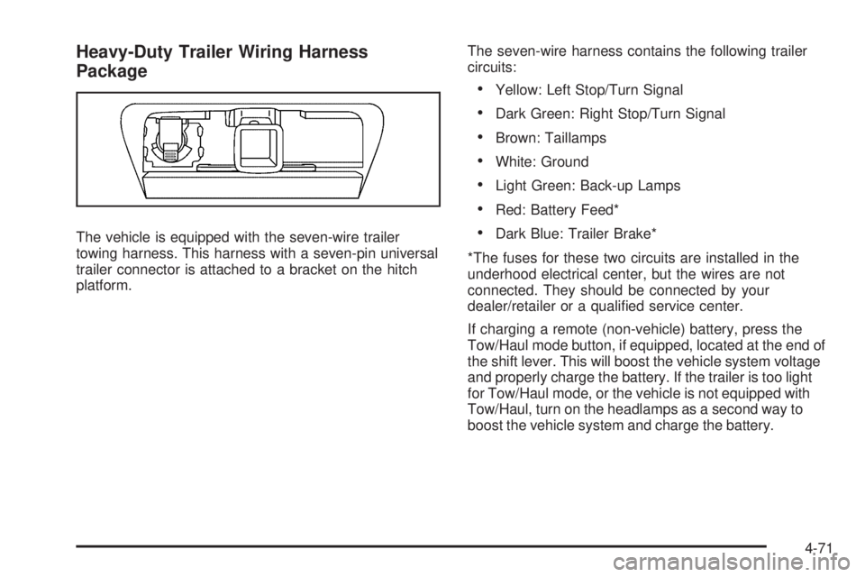
The vehicle is equipped with the seven-wire trailer
towing harness. This harness with a seven-pin universal
trailer connector is attached to a bracket on the hitch
platform.The seven-wire harness contains the following trailer
circuits:
Yellow: Left Stop/Turn Signal
Dark Green: Right Stop/Turn Signal
Brown: Taillamps
White: Ground
Light Green: Back-up Lamps
Red: Battery Feed*
Dark Blue: Trailer Brake*
*The fuses for these two circuits are installed in the
underhood electrical center, but the wires are not
connected. They should be connected by your
dealer/retailer or a quali�ed service center.
If charging a remote (non-vehicle) battery, press the
Tow/Haul mode button, if equipped, located at the end of
the shift lever. This will boost the vehicle system voltage
and properly charge the battery. If the trailer is too light
for Tow/Haul mode, or the vehicle is not equipped with
Tow/Haul, turn on the headlamps as a second way to
boost the vehicle system and charge the battery.
4-71
Page 400 of 578
Electric Brake Control Wiring
Provisions
These wiring provisions are included with the vehicle
as part of the trailer wiring package. These provisions
are for an electric brake controller. The instrument panel
contains blunt cut wires near the data link connector
for the trailer brake controller. The harness contains the
following wires:
Dark Blue: Brake Signal to Trailer Connector
Red/Black: Battery
Light Blue/White: Brake Switch
White: Ground
It should be installed by your dealer/retailer or a
quali�ed service center.
If the vehicle is equipped with an ITBC, the blunt cuts
exist, but are not connected further in the harness.
If an aftermarket trailer brake controller is installed,
the ITBC must be disconnected. Do not power
both ITBC and aftermarket controllers to control
the trailer brakes at the same time.
Trailer Recommendations
Subtract the hitch loads from the Cargo Weight Rating
(CWR). CWR is the maximum weight of the load the
vehicle can carry. It does not include the weight of the
people inside, but you can �gure about 150 lbs. (68 kg)
for each passenger. The total cargo load must not be
more than the vehicles CWR.
Weigh the vehicle with the trailer attached, so
the GVWR or GAWR are not exceeded. If using a
weight-distributing hitch, weigh the vehicle without
the spring bars in place.
The best performance is obtained by correctly spreading
out the weight of the load and choosing the correct
hitch and trailer brakes.
For more information seeTowing a Trailer on page 4-50.
4-72
Page 401 of 578
Service............................................................5-3
Accessories and Modi�cations..........................5-3
California Proposition 65 Warning.....................5-4
California Perchlorate Materials Requirements.....5-4
Doing Your Own Service Work.........................5-4
Adding Equipment to the Outside of
the Vehicle.................................................5-5
Fuel................................................................5-5
Gasoline Octane............................................5-5
Gasoline Speci�cations....................................5-6
California Fuel...............................................5-6
Additives.......................................................5-6
Fuel E85 (85% Ethanol)..................................5-7
Fuels in Foreign Countries...............................5-8
Filling the Tank..............................................5-9
Filling a Portable Fuel Container.....................5-11
Checking Things Under the Hood....................5-12
Hood Release..............................................5-13
Engine Compartment Overview.......................5-14
Engine Oil...................................................5-15
Engine Oil Life System..................................5-18
Engine Air Cleaner/Filter................................5-20
Automatic Transmission Fluid (6-Speed
Transmission)...........................................5-22
Automatic Transmission Fluid (4-Speed
Transmission)...........................................5-25
Cooling System............................................5-28Engine Coolant.............................................5-29
Coolant Surge Tank Pressure Cap..................5-34
Engine Overheating.......................................5-35
Overheated Engine Protection Operating Mode . . .5-37
Engine Fan Noise.........................................5-37
Power Steering Fluid.....................................5-38
Windshield Washer Fluid................................5-39
Brakes........................................................5-40
Battery........................................................5-43
Jump Starting..............................................
.5-44
Rear Axle.......................................................5-49
Four-Wheel Drive............................................5-51
Front Axle......................................................5-52
Headlamp Aiming...........................................5-53
Bulb Replacement..........................................5-56
Halogen Bulbs..............................................5-56
Taillamps, Turn Signal, Stoplamps and
Back-up Lamps.........................................5-57
License Plate Lamp......................................5-58
Replacement Bulbs.......................................5-58
Windshield Wiper Blade Replacement..............5-59
Tires..............................................................5-61
Tire Sidewall Labeling...................................5-62
Tire Terminology and De�nitions.....................5-67
In�ation - Tire Pressure.................................5-70
Tire Pressure Monitor System.........................5-71
Section 5 Service and Appearance Care
5-1
Page 402 of 578
Tire Pressure Monitor Operation.....................5-73
Tire Inspection and Rotation...........................5-76
When It Is Time for New Tires.......................5-77
Buying New Tires.........................................5-78
Different Size Tires and Wheels......................5-80
Uniform Tire Quality Grading..........................5-81
Wheel Alignment and Tire Balance..................5-82
Wheel Replacement......................................5-82
Tire Chains..................................................5-84
If a Tire Goes Flat........................................5-85
Changing a Flat Tire.....................................5-86
Removing the Spare Tire and Tools................5-87
Removing the Flat Tire and Installing the
Spare Tire................................................5-92
Secondary Latch System...............................5-99
Storing a Flat or Spare Tire and Tools...........5-102
Spare Tire.................................................5-106
Appearance Care..........................................5-106
Interior Cleaning.........................................5-106
Fabric/Carpet..............................................5-108
Leather......................................................5-108
Instrument Panel, Vinyl, and Other Plastic
Surfaces.................................................5-109
Care of Safety Belts....................................5-109
Weatherstrips.............................................5-109Washing Your Vehicle..................................5-110
Cleaning Exterior Lamps/Lenses....................5-110
Finish Care................................................5-110
Windshield, Backglass, and Wiper Blades.......5-111
Aluminum or Chrome-Plated Wheels
and Trim................................................5-112
Tires.........................................................5-112
Sheet Metal Damage...................................5-113
Finish Damage...........................................5-113
Underbody Maintenance...............................5-113
Chemical Paint Spotting..............................
.5-113
Vehicle Identi�cation.....................................5-114
Vehicle Identi�cation Number (VIN)................5-114
Service Parts Identi�cation Label...................5-114
Electrical System..........................................5-114
Add-On Electrical Equipment.........................5-114
Windshield Wiper Fuses...............................5-115
Power Windows and Other Power Options......5-115
Fuses and Circuit Breakers..........................5-115
Instrument Panel Fuse Block........................5-116
Center Instrument Panel Fuse Block..............5-118
Underhood Fuse Block................................5-119
Capacities and Speci�cations........................5-122
Section 5 Service and Appearance Care
5-2
Page 403 of 578
Service
For service and parts needs, visit your dealer/retailer.
You will receive genuine GM parts and GM-trained and
supported service people.
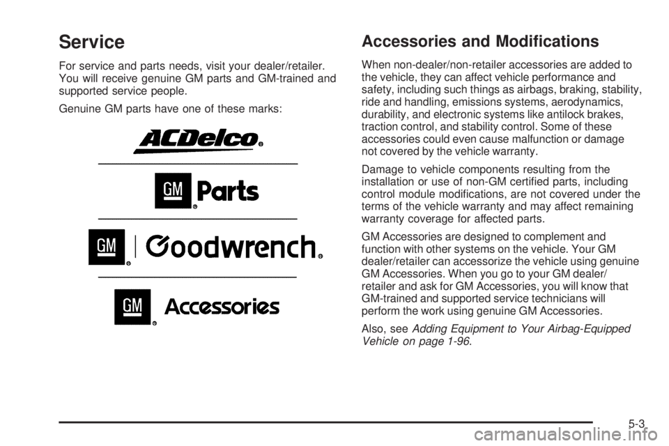
Genuine GM parts have one of these marks:
Accessories and Modi�cations
When non-dealer/non-retailer accessories are added to
the vehicle, they can affect vehicle performance and
safety, including such things as airbags, braking, stability,
ride and handling, emissions systems, aerodynamics,
durability, and electronic systems like antilock brakes,
traction control, and stability control. Some of these
accessories could even cause malfunction or damage
not covered by the vehicle warranty.
Damage to vehicle components resulting from the
installation or use of non-GM certi�ed parts, including
control module modi�cations, are not covered under the
terms of the vehicle warranty and may affect remaining
warranty coverage for affected parts.
GM Accessories are designed to complement and
function with other systems on the vehicle. Your GM
dealer/retailer can accessorize the vehicle using genuine
GM Accessories. When you go to your GM dealer/
retailer and ask for GM Accessories, you will know that
GM-trained and supported service technicians will
perform the work using genuine GM Accessories.
Also, seeAdding Equipment to Your Airbag-Equipped
Vehicle on page 1-96.
5-3