2009 CHERY TIGGO oil level
[x] Cancel search: oil levelPage 1340 of 1903
Downloaded from www.Manualslib.com manuals search engine GENERAL INFORMATION
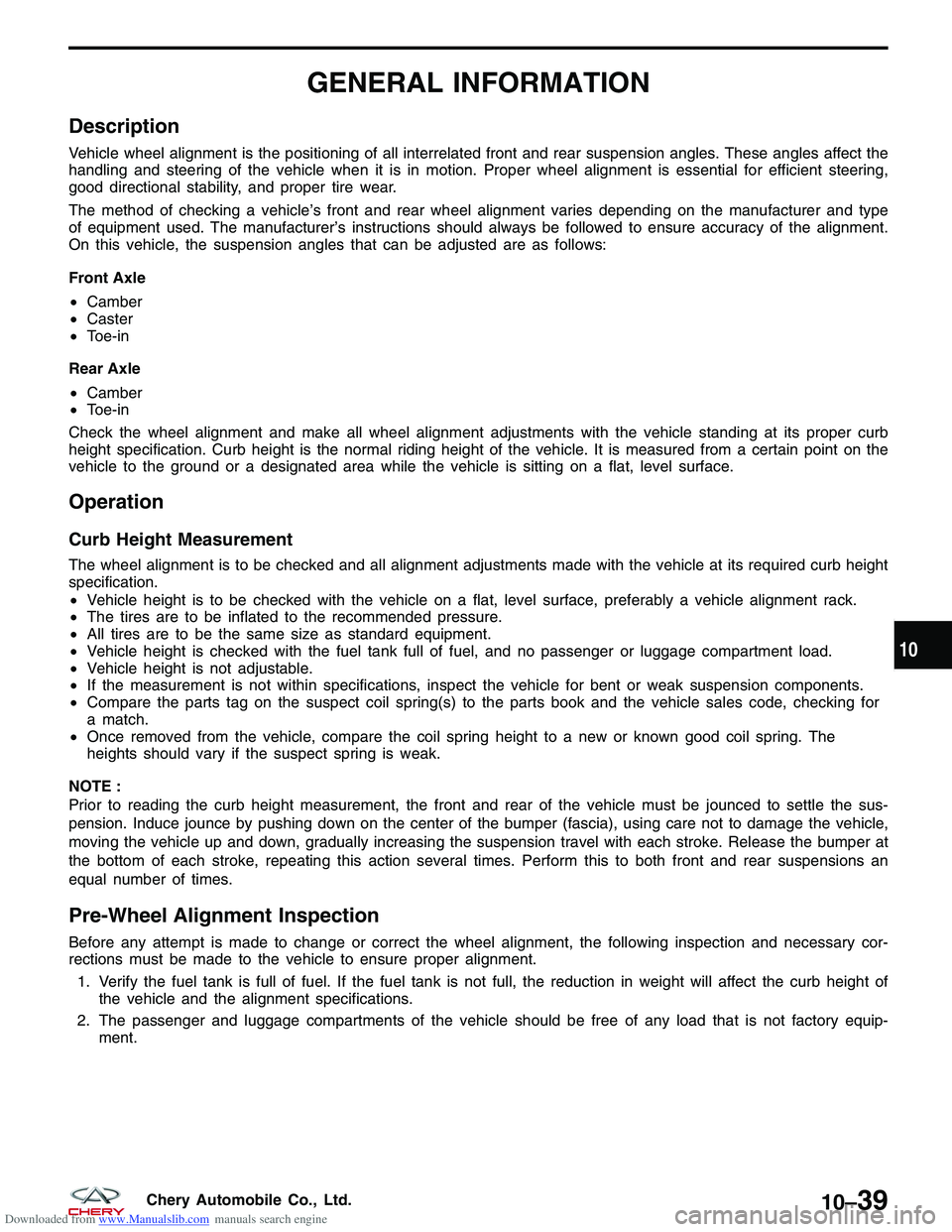
Description
Vehicle wheel alignment is the positioning of all interrelated front and rear suspension angles. These angles affect the
handling and steering of the vehicle when it is in motion. Proper wheel alignment is essential for efficient steering,
good directional stability, and proper tire wear.
The method of checking a vehicle’s front and rear wheel alignment varies depending on the manufacturer and type
of equipment used. The manufacturer’s instructions should always be followed to ensure accuracy of the alignment.
On this vehicle, the suspension angles that can be adjusted are as follows:
Front Axle
•Camber
• Caster
• Toe-in
Rear Axle
• Camber
• Toe-in
Check the wheel alignment and make all wheel alignment adjustments with the vehicle standing at its proper curb
height specification. Curb height is the normal riding height of the vehicle. It is measured from a certain point on the
vehicle to the ground or a designated area while the vehicle is sitting on a flat, level surface.
Operation
Curb Height Measurement
The wheel alignment is to be checked and all alignment adjustments made with the vehicle at its required curb height
specification.
• Vehicle height is to be checked with the vehicle on a flat, level surface, preferably a vehicle alignment rack.
• The tires are to be inflated to the recommended pressure.
• All tires are to be the same size as standard equipment.
• Vehicle height is checked with the fuel tank full of fuel, and no passenger or luggage compartment load.
• Vehicle height is not adjustable.
• If the measurement is not within specifications, inspect the vehicle for bent or weak suspension components.
• Compare the parts tag on the suspect coil spring(s) to the parts book and the vehicle sales code, checking for
a match.
• Once removed from the vehicle, compare the coil spring height to a new or known good coil spring. The
heights should vary if the suspect spring is weak.
NOTE :
Prior to reading the curb height measurement, the front and rear of the vehicle must be jounced to settle the sus-
pension. Induce jounce by pushing down on the center of the bumper (fascia), using care not to damage the vehicle,
moving the vehicle up and down, gradually increasing the suspension travel with each stroke. Release the bumper at
the bottom of each stroke, repeating this action several times. Perform this to both front and rear suspensions an
equal number of times.
Pre-Wheel Alignment Inspection
Before any attempt is made to change or correct the wheel alignment, the following inspection and necessary cor-
rections must be made to the vehicle to ensure proper alignment. 1. Verify the fuel tank is full of fuel. If the fuel tank is not full, the reduction in weight will affect the curb height of the vehicle and the alignment specifications.
2. The passenger and luggage compartments of the vehicle should be free of any load that is not factory equip- ment.
10
10–39Chery Automobile Co., Ltd.
Page 1495 of 1903
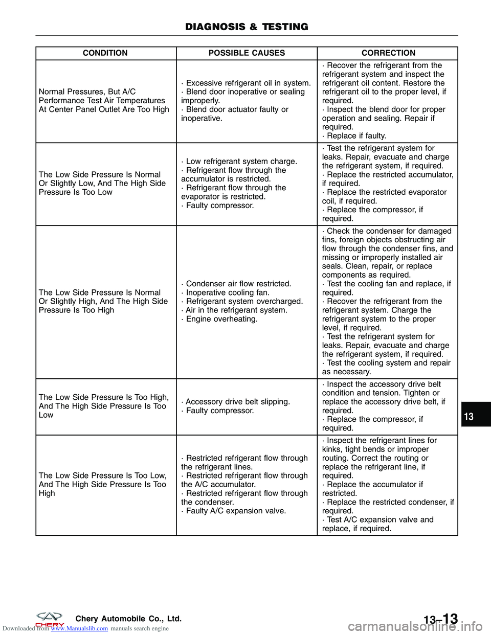
Downloaded from www.Manualslib.com manuals search engine CONDITIONPOSSIBLE CAUSES CORRECTION
Normal Pressures, But A/C
Performance Test Air Temperatures
At Center Panel Outlet Are Too High · Excessive refrigerant oil in system.
· Blend door inoperative or sealing
improperly.
· Blend door actuator faulty or
inoperative.· Recover the refrigerant from the
refrigerant system and inspect the
refrigerant oil content. Restore the
refrigerant oil to the proper level, if
required.
· Inspect the blend door for proper
operation and sealing. Repair if
required.
· Replace if faulty.
The Low Side Pressure Is Normal
Or Slightly Low, And The High Side
Pressure Is Too Low · Low refrigerant system charge.
· Refrigerant flow through the
accumulator is restricted.
· Refrigerant flow through the
evaporator is restricted.
· Faulty compressor.· Test the refrigerant system for
leaks. Repair, evacuate and charge
the refrigerant system, if required.
· Replace the restricted accumulator,
if required.
· Replace the restricted evaporator
coil, if required.
· Replace the compressor, if
required.
The Low Side Pressure Is Normal
Or Slightly High, And The High Side
Pressure Is Too High · Condenser air flow restricted.
· Inoperative cooling fan.
· Refrigerant system overcharged.
· Air in the refrigerant system.
· Engine overheating.· Check the condenser for damaged
fins, foreign objects obstructing air
flow through the condenser fins, and
missing or improperly installed air
seals. Clean, repair, or replace
components as required.
· Test the cooling fan and replace, if
required.
· Recover the refrigerant from the
refrigerant system. Charge the
refrigerant system to the proper
level, if required.
· Test the refrigerant system for
leaks. Repair, evacuate and charge
the refrigerant system, if required.
· Test the cooling system and repair
as necessary.
The Low Side Pressure Is Too High,
And The High Side Pressure Is Too
Low · Accessory drive belt slipping.
· Faulty compressor.· Inspect the accessory drive belt
condition and tension. Tighten or
replace the accessory drive belt, if
required.
· Replace the compressor, if
required.
The Low Side Pressure Is Too Low,
And The High Side Pressure Is Too
High · Restricted refrigerant flow through
the refrigerant lines.
· Restricted refrigerant flow through
the A/C accumulator.
· Restricted refrigerant flow through
the condenser.
· Faulty A/C expansion valve.· Inspect the refrigerant lines for
kinks, tight bends or improper
routing. Correct the routing or
replace the refrigerant line, if
required.
· Replace the accumulator if
restricted.
· Replace the restricted condenser, if
required.
· Test A/C expansion valve and
replace, if required.
DIAGNOSIS & TESTING
13
13–13Chery Automobile Co., Ltd.
Page 1518 of 1903
Downloaded from www.Manualslib.com manuals search engine 12. If the noise is from liquid refrigerant slugging in the A/C suction line, replace the A/C accumulator and check therefrigerant oil level and the refrigerant system charge.
13. If a slugging condition still exists after replacing the A/C accumulator, replace the A/C compressor.
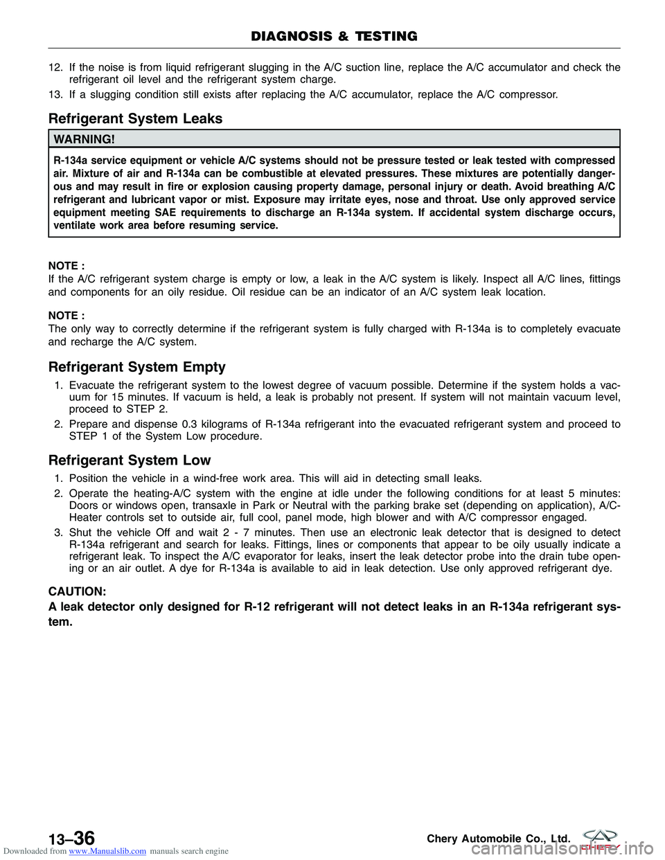
Refrigerant System Leaks
WARNING!
R-134a service equipment or vehicle A/C systems should not be pressure tested or leak tested with compressed
air. Mixture of air and R-134a can be combustible at elevated pressures. These mixtures are potentially danger-
ous and may result in fire or explosion causing property damage, personal injury or death. Avoid breathing A/C
refrigerant and lubricant vapor or mist. Exposure may irritate eyes, nose and throat. Use only approved service
equipment meeting SAE requirements to discharge an R-134a system. If accidental system discharge occurs,
ventilate work area before resuming service.
NOTE :
If the A/C refrigerant system charge is empty or low, a leak in the A/C system is likely. Inspect all A/C lines, fittings
and components for an oily residue. Oil residue can be an indicator of an A/C system leak location.
NOTE :
The only way to correctly determine if the refrigerant system is fully charged with R-134a is to completely evacuate
and recharge the A/C system.
Refrigerant System Empty
1. Evacuate the refrigerant system to the lowest degree of vacuum possible. Determine if the system holds a vac- uum for 15 minutes. If vacuum is held, a leak is probably not present. If system will not maintain vacuum level,
proceed to STEP 2.
2. Prepare and dispense 0.3 kilograms of R-134a refrigerant into the evacuated refrigerant system and proceed to STEP 1 of the System Low procedure.
Refrigerant System Low
1. Position the vehicle in a wind-free work area. This will aid in detecting small leaks.
2. Operate the heating-A/C system with the engine at idle under the following conditions for at least 5 minutes:Doors or windows open, transaxle in Park or Neutral with the parking brake set (depending on application), A/C-
Heater controls set to outside air, full cool, panel mode, high blower and with A/C compressor engaged.
3. Shut the vehicle Off and wait2-7minutes. Then use an electronic leak detector that is designed to detect R-134a refrigerant and search for leaks. Fittings, lines or components that appear to be oily usually indicate a
refrigerant leak. To inspect the A/C evaporator for leaks, insert the leak detector probe into the drain tube open-
ing or an air outlet. A dye for R-134a is available to aid in leak detection. Use only approved refrigerant dye.
CAUTION:
A leak detector only designed for R-12 refrigerant will not detect leaks in an R-134a refrigerant sys-
tem.
DIAGNOSIS & TESTING
13–36Chery Automobile Co., Ltd.
Page 1603 of 1903
Downloaded from www.Manualslib.com manuals search engine CHIME
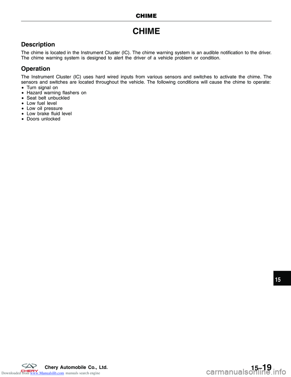
Description
The chime is located in the Instrument Cluster (IC). The chime warning system is an audible notification to the driver.
The chime warning system is designed to alert the driver of a vehicle problem or condition.
Operation
The Instrument Cluster (IC) uses hard wired inputs from various sensors and switches to activate the chime. The
sensors and switches are located throughout the vehicle. The following conditions will cause the chime to operate:
•Turn signal on
• Hazard warning flashers on
• Seat belt unbuckled
• Low fuel level
• Low oil pressure
• Low brake fluid level
• Doors unlocked
CHIME
15
15–19Chery Automobile Co., Ltd.
Page 1636 of 1903
Downloaded from www.Manualslib.com manuals search engine INSTRUMENT CLUSTER
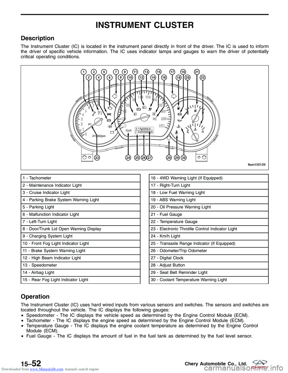
Description
The Instrument Cluster (IC) is located in the instrument panel directly in front of the driver. The IC is used to inform
the driver of specific vehicle information. The IC uses indicator lamps and gauges to warn the driver of potentially
critical operating conditions.
Operation
The Instrument Cluster (IC) uses hard wired inputs from various sensors and switches. The sensors and switches are
located throughout the vehicle. The IC displays the following gauges:
•Speedometer - The IC displays the vehicle speed as determined by the Engine Control Module (ECM).
• Tachometer - The IC displays the engine speed as determined by the Engine Control Module (ECM).
• Temperature Gauge - The IC displays the engine coolant temperature as determined by the Engine Control
Module (ECM).
• Fuel Gauge - The IC displays the amount of fuel in the fuel tank as determined by the fuel level sensor.
1 - Tachometer
2 - Maintenance Indicator Light
3 - Cruise Indicator Light
4 - Parking Brake System Warning Light
5 - Parking Light
6 - Malfunction Indicator Light
7 - Left-Turn Light
8 - Door/Trunk Lid Open Warning Display
9 - Charging System Light
10 - Front Fog Light Indicator Light
11 - Brake System Warning Light
12 - High Beam Indicator Light
13 - Speedometer
14 - Airbag Light
15 - Rear Fog Light Indicator Light16 - 4WD Warning Light (If Equipped)
17 - Right-Turn Light
18 - Low Fuel Warning Light
19 - ABS Warning Light
20 - Oil Pressure Warning Light
21 - Fuel Gauge
22 - Temperature Gauge
23 - Electronic Throttle Control Indicator Light
24 - Km/h Light
25 - Transaxle Range Indicator (If Equipped)
26 - Odometer/Trip Odometer
27 - Digital Clock
28 - Adjust Button
29 - Seat Belt Reminder Light
30 - Coolant Temperature Warning Light
LTSM150129
15–52Chery Automobile Co., Ltd.
Page 1646 of 1903
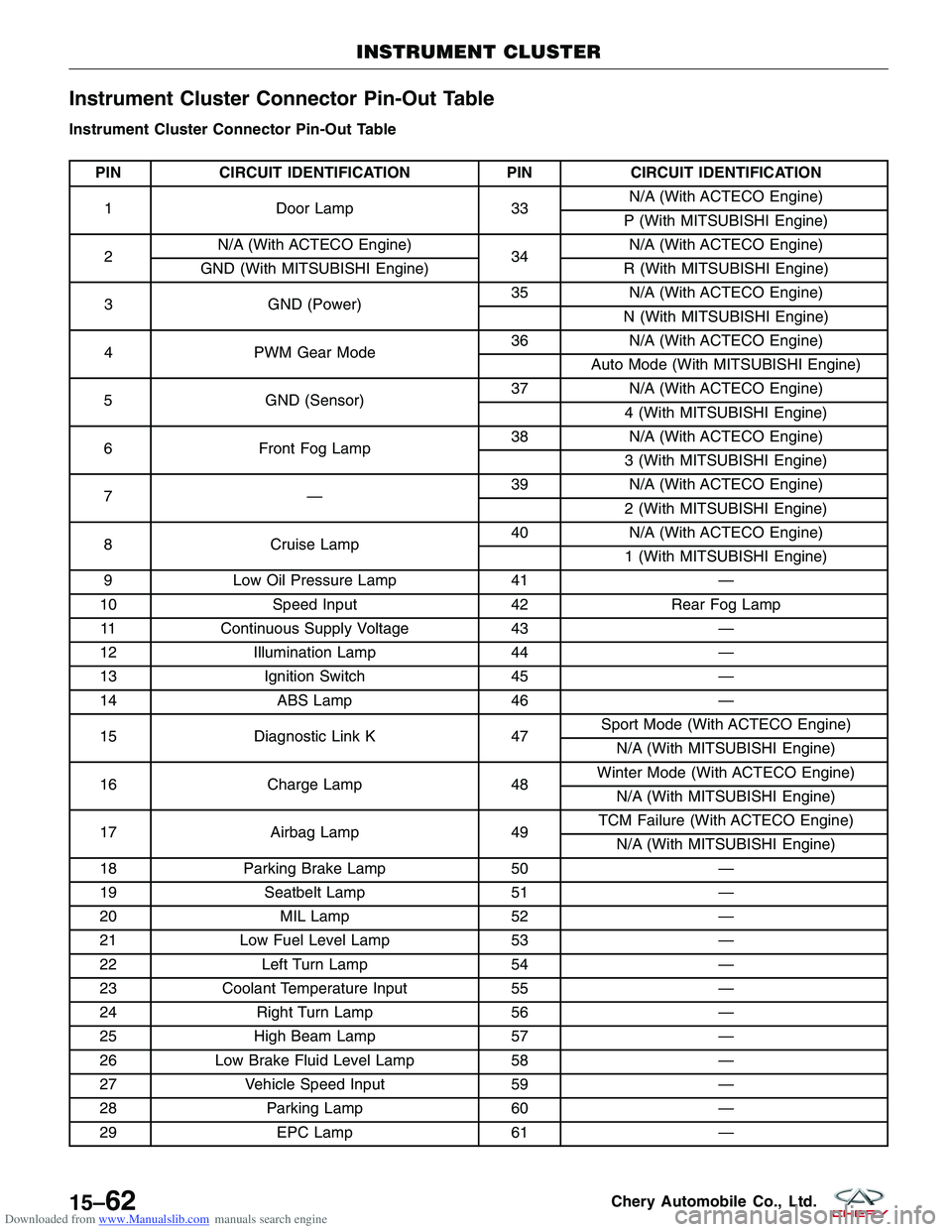
Downloaded from www.Manualslib.com manuals search engine Instrument Cluster Connector Pin-Out Table
Instrument Cluster Connector Pin-Out Table
PINCIRCUIT IDENTIFICATION PINCIRCUIT IDENTIFICATION
1 Door Lamp 33N/A (With ACTECO Engine)
P (With MITSUBISHI Engine)
2 N/A (With ACTECO Engine)
34N/A (With ACTECO Engine)
GND (With MITSUBISHI Engine) R (With MITSUBISHI Engine)
3 GND (Power) 35
N/A (With ACTECO Engine)
N (With MITSUBISHI Engine)
4 PWM Gear Mode 36
N/A (With ACTECO Engine)
Auto Mode (With MITSUBISHI Engine)
5 GND (Sensor) 37
N/A (With ACTECO Engine)
4 (With MITSUBISHI Engine)
6 Front Fog Lamp 38
N/A (With ACTECO Engine)
3 (With MITSUBISHI Engine)
7— 39
N/A (With ACTECO Engine)
2 (With MITSUBISHI Engine)
8 Cruise Lamp 40
N/A (With ACTECO Engine)
1 (With MITSUBISHI Engine)
9 Low Oil Pressure Lamp 41—
10 Speed Input 42Rear Fog Lamp
11 Continuous Supply Voltage 43—
12 Illumination Lamp 44—
13 Ignition Switch 45—
14 ABS Lamp 46—
15 Diagnostic Link K 47Sport Mode (With ACTECO Engine)
N/A (With MITSUBISHI Engine)
16 Charge Lamp 48Winter Mode (With ACTECO Engine)
N/A (With MITSUBISHI Engine)
17 Airbag Lamp 49TCM Failure (With ACTECO Engine)
N/A (With MITSUBISHI Engine)
18 Parking Brake Lamp 50—
19 Seatbelt Lamp 51—
20 MIL Lamp 52—
21 Low Fuel Level Lamp 53—
22 Left Turn Lamp 54—
23 Coolant Temperature Input 55—
24 Right Turn Lamp 56—
25 High Beam Lamp 57—
26 Low Brake Fluid Level Lamp 58—
27 Vehicle Speed Input 59—
28 Parking Lamp 60—
29 EPC Lamp 61—
INSTRUMENT CLUSTER
15–62Chery Automobile Co., Ltd.
Page 1875 of 1903
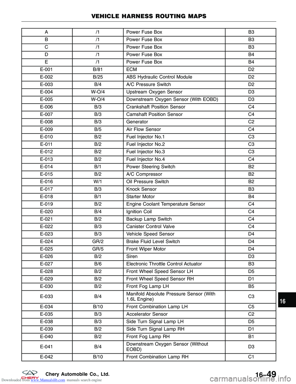
Downloaded from www.Manualslib.com manuals search engine A/1Power Fuse Box B3
B /1Power Fuse Box B3
C /1Power Fuse Box B3
D /1Power Fuse Box B4
E /1Power Fuse Box B4
E-001 B/81 ECM D2
E-002 B/25 ABS Hydraulic Control Module D2
E-003 B/4A/C Pressure Switch D2
E-004 W-O/4 Upstream Oxygen Sensor D3
E-005 W-O/4 Downstream Oxygen Sensor (With EOBD) D3
E-006 B/3Crankshaft Position Sensor C4
E-007 B/3Camshaft Position Sensor C4
E-008 B/3Generator C2
E-009 B/5Air Flow Sensor C4
E-010 B/2Fuel Injector No.1 C3
E-011 B/2Fuel Injector No.2 C3
E-012 B/2Fuel Injector No.3 C3
E-013 B/2Fuel Injector No.4 C4
E-014 B/1Power Steering Switch B2
E-015 B/2A/C Compressor B2
E-016 W/1 Oil Pressure Switch B2
E-017 B/3Knock Sensor B3
E-018 B/1Starter Motor B4
E-019 B/2Engine Coolant Temperature Sensor C4
E-020 B/4Ignition Coil C4
E-021 B/2Backup Lamp Switch C4
E-022 B/3Canister Control Valve C4
E-023 B/3Vehicle Speed Sensor D4
E-024 GR/2 Brake Fluid Level Switch D4
E-025 GR/5 Front Wiper Motor D4
E-026 B/2Siren D3
E-027 B/6Electronic Throttle Control Actuator B3
E-028 B/2Front Wheel Speed Sensor LH D5
E-029 B/2Front Wheel Speed Sensor RH D1
E-030 B/2Front Fog Lamp LH B5
E-033 B/4Manifold Absolute Pressure Sensor (With
1.6L Engine) C3
E-034 B/10 Front Combination Lamp LH C5
E-035 B/3Accelerator Sensor C2
E-038 B/3Side Turn Signal Lamp LH D5
E-039 B/2Side Turn Signal Lamp RH D1
E-040 B/2Front Fog Lamp RH B1
E-041 B/4Downstream Oxygen Sensor (Without
EOBD) D3
E-042 B/10 Front Combination Lamp RH C1
VEHICLE HARNESS ROUTING MAPS
16
16–49Chery Automobile Co., Ltd.