2009 CHERY TIGGO tow
[x] Cancel search: towPage 1211 of 1903
Downloaded from www.Manualslib.com manuals search engine Assembly
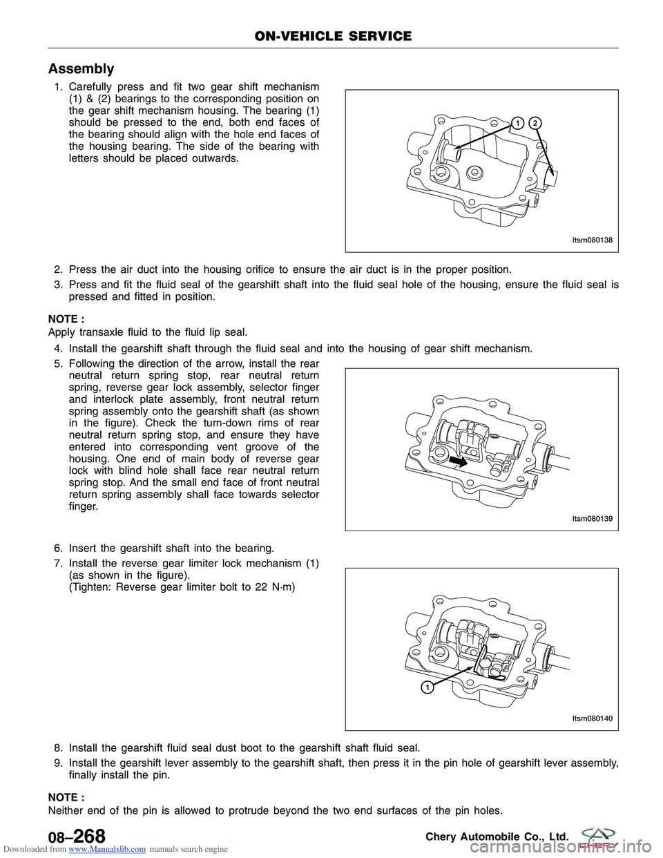
1. Carefully press and fit two gear shift mechanism(1) & (2) bearings to the corresponding position on
the gear shift mechanism housing. The bearing (1)
should be pressed to the end, both end faces of
the bearing should align with the hole end faces of
the housing bearing. The side of the bearing with
letters should be placed outwards.
2. Press the air duct into the housing orifice to ensure the air duct is in the proper position.
3. Press and fit the fluid seal of the gearshift shaft into the fluid seal hole of the housing, ensure the fluid seal is pressed and fitted in position.
NOTE :
Apply transaxle fluid to the fluid lip seal. 4. Install the gearshift shaft through the fluid seal and into the housing of gear shift mechanism.
5. Following the direction of the arrow, install the rear neutral return spring stop, rear neutral return
spring, reverse gear lock assembly, selector finger
and interlock plate assembly, front neutral return
spring assembly onto the gearshift shaft (as shown
in the figure). Check the turn-down rims of rear
neutral return spring stop, and ensure they have
entered into corresponding vent groove of the
housing. One end of main body of reverse gear
lock with blind hole shall face rear neutral return
spring stop. And the small end face of front neutral
return spring assembly shall face towards selector
finger.
6. Insert the gearshift shaft into the bearing.
7. Install the reverse gear limiter lock mechanism (1) (as shown in the figure).
(Tighten: Reverse gear limiter bolt to 22 N·m)
8. Install the gearshift fluid seal dust boot to the gearshift shaft fluid seal.
9. Install the gearshift lever assembly to the gearshift shaft, then press it in the pin hole of gearshift lever assembly, finally install the pin.
NOTE :
Neither end of the pin is allowed to protrude beyond the two end surfaces of the pin holes.
ON-VEHICLE SERVICE
LTSM080138
LTSM080139
LTSM080140
08–268Chery Automobile Co., Ltd.
Page 1305 of 1903
Downloaded from www.Manualslib.com manuals search engine WARNING!
Do not remove the strut rod nut while the strut assembly is installed in the vehicle, or before the coil spring is
compressed with a spring compressor. The spring is held under high pressure and must be compressed before
the strut rod nut can be removed.
CAUTION:
At no time when servicing a vehicle can a sheet metal screw, bolt, or other metal fastener be
installed in the shock tower to replace the original plastic clamp. It may come in contact with the
strut or coil spring.
CAUTION:
The wheel bearing will be damaged if the vehicle is rolled with the axle shaft hub nut loose.
Operation
The front suspension utilizes a MacPherson strut system. This suspension system incorporates a strut assembly that
takes the place of the upper arm and ball joint. The strut performs the function of a shock absorber and is encom-
passed by a coil spring.
Specifications
Torque Specifications
DESCRIPTIONTORQUE (N·m)
Connecting Rod And Front Stabilizer Bar 40 - 50
Connect The Right And Left Assembly Of Front Drive
Shaft With Brake Disc 260 - 270
Control Arm And Sub-Frame 170 - 190
Connect Intermediate Propeller Shaft With Vehicle Body 58 - 68
Connecting Rod With Lower Suspension Lever 40 - 50
Connect Control Arm Knuckle Pin With Knuckle
Assembly 110 - 130
Connect Control Arm Knuckle Pin With Control Arm 140 - 160
Front Connecting Rod And Front Shock Absorber 40 - 50
Front Axle Shaft Nut 135
Fix Stabilizer Bar Clamp To Sub-Frame 22 - 28
Front Shock Absorber and Coil Spring 100 - 120
Front Suspension Strut And Vehicle Body 45 - 55
Front Suspension And Bracket 75 - 85
Insert From The Lower Part Of Sub-Frame, And The
Bolt Is On The Suspension. The Middle Part Shall Be
Clamped To The Main Longitudinal Beam Of Engine 110 - 130
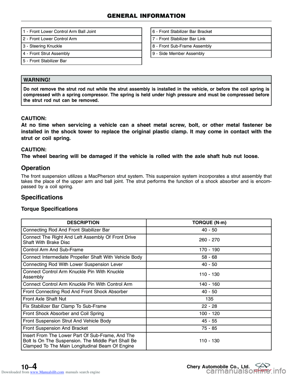
1 - Front Lower Control Arm Ball Joint
2 - Front Lower Control Arm
3 - Steering Knuckle
4 - Front Strut Assembly
5 - Front Stabilizer Bar6 - Front Stabilizer Bar Bracket
7 - Front Stabilizer Bar Link
8 - Front Sub-Frame Assembly
9 - Side Member Assembly
GENERAL INFORMATION
LTSM100008
10–4Chery Automobile Co., Ltd.
Page 1306 of 1903
Downloaded from www.Manualslib.com manuals search engine DESCRIPTIONTORQUE (N·m)
Longitudinal Beam And Flat Gasket Of Vehicle (Front)
Body 74-86
One On Each Side To Connect Upper Link With Towing
Arm 100 - 120
One On Each Side To Connect Lower Control Arm With
Towing Arm 100 - 120
Steering Knuckle And Suspension Strut 110 - 130
Soft Gasket And Bracket Of Front Suspension 75 - 85
Steering Knuckle Tie Rod And Steering Knuckle 32 - 38
Sub-Frame And Gasket Of Vehicle (Front) Body 170 - 190
Sub-Frame And Longitudinal Beam Welding Assembly 75 - 85
Steering Gear And Sub-Frame 75 - 85
Wheel Mounting Nut \
\
110
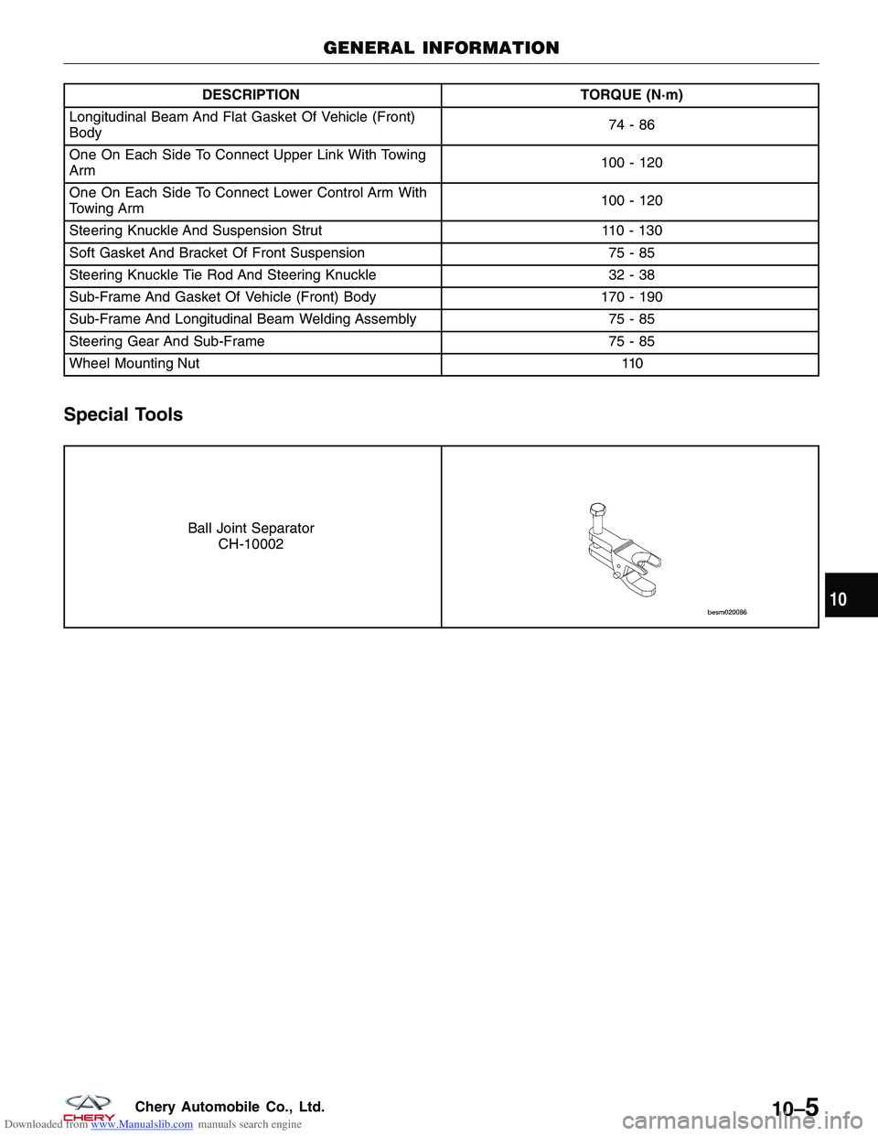
Special Tools
Ball Joint Separator
CH-10002
GENERAL INFORMATION
10
10–5Chery Automobile Co., Ltd.
Page 1314 of 1903
Downloaded from www.Manualslib.com manuals search engine Front Strut Assembly
Description
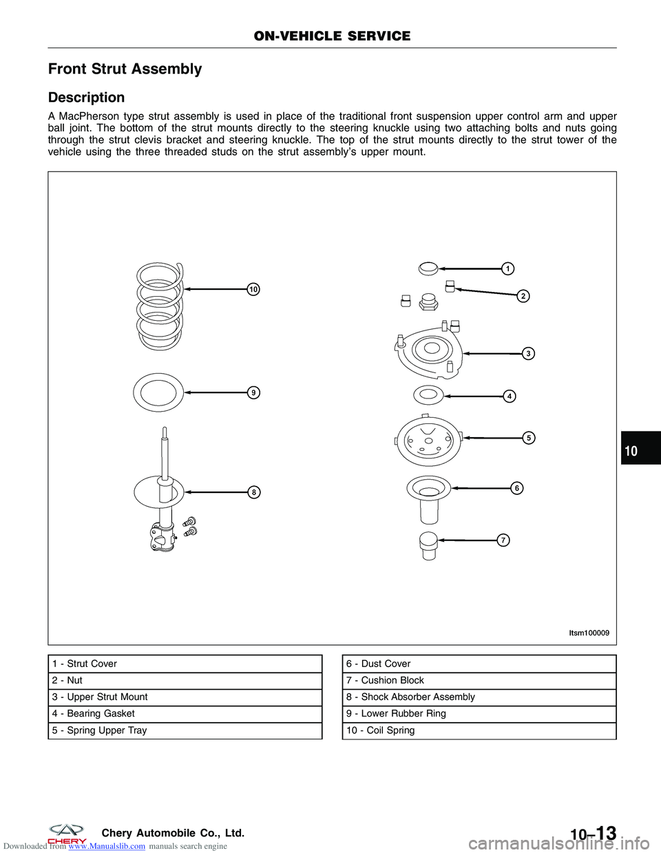
A MacPherson type strut assembly is used in place of the traditional front suspension upper control arm and upper
ball joint. The bottom of the strut mounts directly to the steering knuckle using two attaching bolts and nuts going
through the strut clevis bracket and steering knuckle. The top of the strut mounts directly to the strut tower of the
vehicle using the three threaded studs on the strut assembly’s upper mount.
1 - Strut Cover
2 - Nut
3 - Upper Strut Mount
4 - Bearing Gasket
5 - Spring Upper Tray6 - Dust Cover
7 - Cushion Block
8 - Shock Absorber Assembly
9 - Lower Rubber Ring
10 - Coil Spring
ON-VEHICLE SERVICE
LTSM100009
10
10–13Chery Automobile Co., Ltd.
Page 1316 of 1903
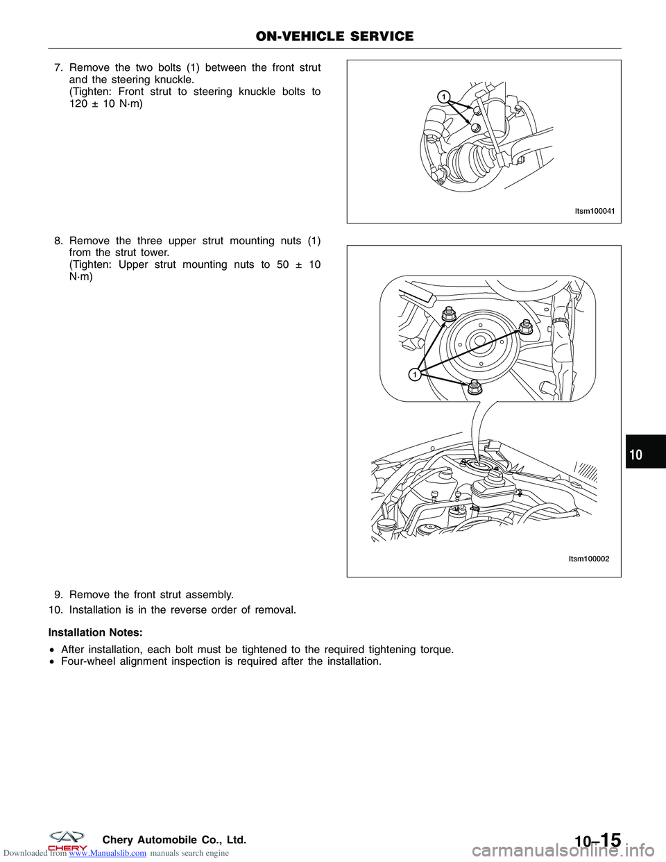
Downloaded from www.Manualslib.com manuals search engine 7. Remove the two bolts (1) between the front strutand the steering knuckle.
(Tighten: Front strut to steering knuckle bolts to
120 ± 10 N·m)
8. Remove the three upper strut mounting nuts (1) from the strut tower.
(Tighten: Upper strut mounting nuts to 50 ± 10
N·m)
9. Remove the front strut assembly.
10. Installation is in the reverse order of removal.
Installation Notes:
• After installation, each bolt must be tightened to the required tightening torque.
• Four-wheel alignment inspection is required after the installation.
ON-VEHICLE SERVICE
LTSM100041
LTSM100002
10
10–15Chery Automobile Co., Ltd.
Page 1317 of 1903
Downloaded from www.Manualslib.com manuals search engine Front Coil Spring
Description
A coil-over front strut assembly supports each front coil spring. The top of the strut assembly mounts to the strut
tower.
Operation
Coil springs are designed to store energy and subsequently release it and to absorb shock and maintain a force
between contacting surfaces. Coil springs are rated for specific vehicle applications.
NOTE :
Each component is serviced by removing the strut assembly from the vehicle and disassembling it. Coil springs are
rated separately for each corner or side of the vehicle depending on optional equipment and type of vehicle service.
If a coil spring requires replacement, be sure that it is replaced with a spring meeting the correct load rating for the
vehicle and its specific options.
Removal & Installation
CAUTION:
At no time when servicing a vehicle can a sheet metal screw, bolt or other metal fastener be
installed into the strut tower to take the place of an original plastic clamp. Also, do not drill holes
into the front strut tower for the installation of any metal fasteners into the strut tower area indi-
cated.
1. Raise and support the vehicle.
2. Remove the front strut assembly (See Front Strut Removal & Installation in Section 10 Suspension).
WARNING!
Do not remove the strut rod nut before the coil spring is properly compressed. The coil spring is held under
pressure. The coil spring must be compressed, removing spring tension from the upper mount and bearing,
before the strut rod nut is removed.
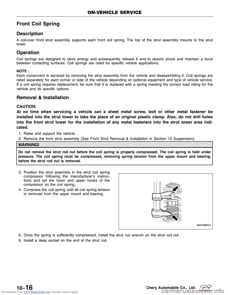
3. Position the strut assembly in the strut coil springcompressor following the manufacturer’s instruc-
tions and set the lower and upper hooks of the
compressor on the coil spring.
4. Compress the coil spring until all coil spring tension is removed from the upper mount and bearing.
5. Once the spring is sufficiently compressed, install the strut nut wrench on the strut rod nut.
6. Install a deep socket on the end of the strut rod.
ON-VEHICLE SERVICE
LTSM100014
10–16Chery Automobile Co., Ltd.
Page 1423 of 1903
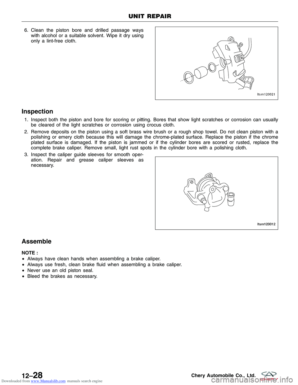
Downloaded from www.Manualslib.com manuals search engine 6. Clean the piston bore and drilled passage wayswith alcohol or a suitable solvent. Wipe it dry using
only a lint-free cloth.
Inspection
1. Inspect both the piston and bore for scoring or pitting. Bores that show light scratches or corrosion can usuallybe cleared of the light scratches or corrosion using crocus cloth.
2. Remove deposits on the piston using a soft brass wire brush or a rough shop towel. Do not clean piston with a polishing or emery cloth because this will damage the chrome-plated surface. Replace the piston if the chrome
plated surface is damaged. If the piston is jammed or if the cylinder bores are scored or rusted, replace the
complete brake caliper. Remove small, light rust spots in the cylinder bore with a polishing cloth.
3. Inspect the caliper guide sleeves for smooth oper- ation. Repair and grease caliper sleeves as
necessary.
Assemble
NOTE :
•Always have clean hands when assembling a brake caliper.
• Always use fresh, clean brake fluid when assembling a brake caliper.
• Never use an old piston seal.
• Bleed the brakes as necessary.
UNIT REPAIR
LTSM120021
LTSM120012
12–28Chery Automobile Co., Ltd.
Page 1426 of 1903
Downloaded from www.Manualslib.com manuals search engine CAUTION:
Do not use a screwdriver or other metal tool for seal removal. Using such tools can scratch the
bore or leave burrs on the seal groove edges.
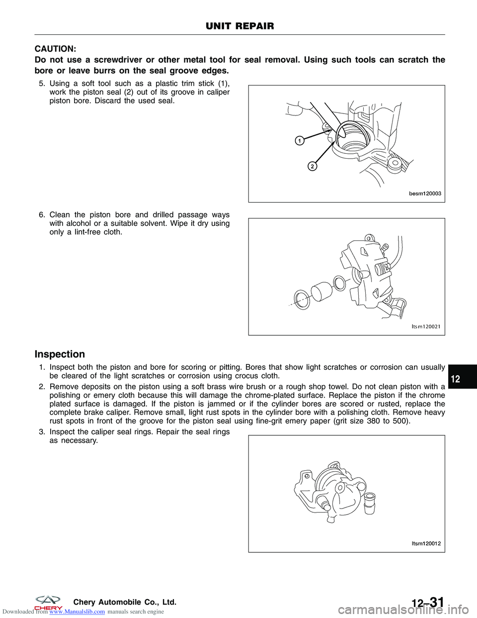
5. Using a soft tool such as a plastic trim stick (1),work the piston seal (2) out of its groove in caliper
piston bore. Discard the used seal.
6. Clean the piston bore and drilled passage ways with alcohol or a suitable solvent. Wipe it dry using
only a lint-free cloth.
Inspection
1. Inspect both the piston and bore for scoring or pitting. Bores that show light scratches or corrosion can usuallybe cleared of the light scratches or corrosion using crocus cloth.
2. Remove deposits on the piston using a soft brass wire brush or a rough shop towel. Do not clean piston with a polishing or emery cloth because this will damage the chrome-plated surface. Replace the piston if the chrome
plated surface is damaged. If the piston is jammed or if the cylinder bores are scored or rusted, replace the
complete brake caliper. Remove small, light rust spots in the cylinder bore with a polishing cloth. Remove heavy
rust spots in front of the groove for the piston seal using fine-grit emery paper (grit size 380 to 500).
3. Inspect the caliper seal rings. Repair the seal rings as necessary.
UNIT REPAIR
BESM120003
LTSM120021
LTSM120012
12
12–31Chery Automobile Co., Ltd.