Page 1474 of 1903
Downloaded from www.Manualslib.com manuals search engine PARKING BRAKE
GENERAL INFORMATION12-80
Description 12-80
Operation 12-80
Specifications 12-80
Special Tools 12-80
Electrical Schematics 12-81
DIAGNOSIS & TESTING12-82
Parking Brake Warning Light 12-82
Parking Brake Operation 12-82
Parking Brake Adjustment 12-82
ON-VEHICLE SERVICE12-84
Parking Brake Lever 12-84
Removal & Installation 12-84
Parking Brake Cable 12-85
Removal & Installation 12-85
Parking Brake Shoes 12-86
Removal & Installation 12-86
12
12–79Chery Automobile Co., Ltd.
Page 1477 of 1903

Downloaded from www.Manualslib.com manuals search engine DIAGNOSIS & TESTING
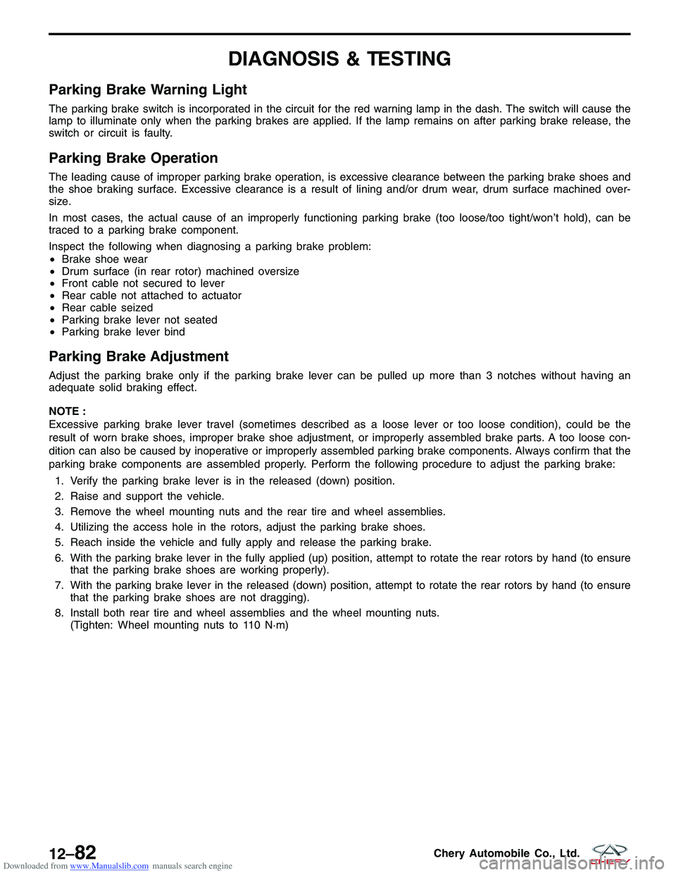
Parking Brake Warning Light
The parking brake switch is incorporated in the circuit for the red warning lamp in the dash. The switch will cause the
lamp to illuminate only when the parking brakes are applied. If the lamp remains on after parking brake release, the
switch or circuit is faulty.
Parking Brake Operation
The leading cause of improper parking brake operation, is excessive clearance between the parking brake shoes and
the shoe braking surface. Excessive clearance is a result of lining and/or drum wear, drum surface machined over-
size.
In most cases, the actual cause of an improperly functioning parking brake (too loose/too tight/won’t hold), can be
traced to a parking brake component.
Inspect the following when diagnosing a parking brake problem:
•Brake shoe wear
• Drum surface (in rear rotor) machined oversize
• Front cable not secured to lever
• Rear cable not attached to actuator
• Rear cable seized
• Parking brake lever not seated
• Parking brake lever bind
Parking Brake Adjustment
Adjust the parking brake only if the parking brake lever can be pulled up more than 3 notches without having an
adequate solid braking effect.
NOTE :
Excessive parking brake lever travel (sometimes described as a loose lever or too loose condition), could be the
result of worn brake shoes, improper brake shoe adjustment, or improperly assembled brake parts. A too loose con-
dition can also be caused by inoperative or improperly assembled parking brake components. Always confirm that the
parking brake components are assembled properly. Perform the following procedure to adjust the parking brake:
1. Verify the parking brake lever is in the released (down) position.
2. Raise and support the vehicle.
3. Remove the wheel mounting nuts and the rear tire and wheel assemblies.
4. Utilizing the access hole in the rotors, adjust the parking brake shoes.
5. Reach inside the vehicle and fully apply and release the parking brake.
6. With the parking brake lever in the fully applied (up) position, attempt to rotate the rear rotors by hand (to ensure that the parking brake shoes are working properly).
7. With the parking brake lever in the released (down) position, attempt to rotate the rear rotors by hand (to ensure that the parking brake shoes are not dragging).
8. Install both rear tire and wheel assemblies and the wheel mounting nuts. (Tighten: Wheel mounting nuts to 110 N·m)
12–82Chery Automobile Co., Ltd.
Page 1636 of 1903

Downloaded from www.Manualslib.com manuals search engine INSTRUMENT CLUSTER
Description
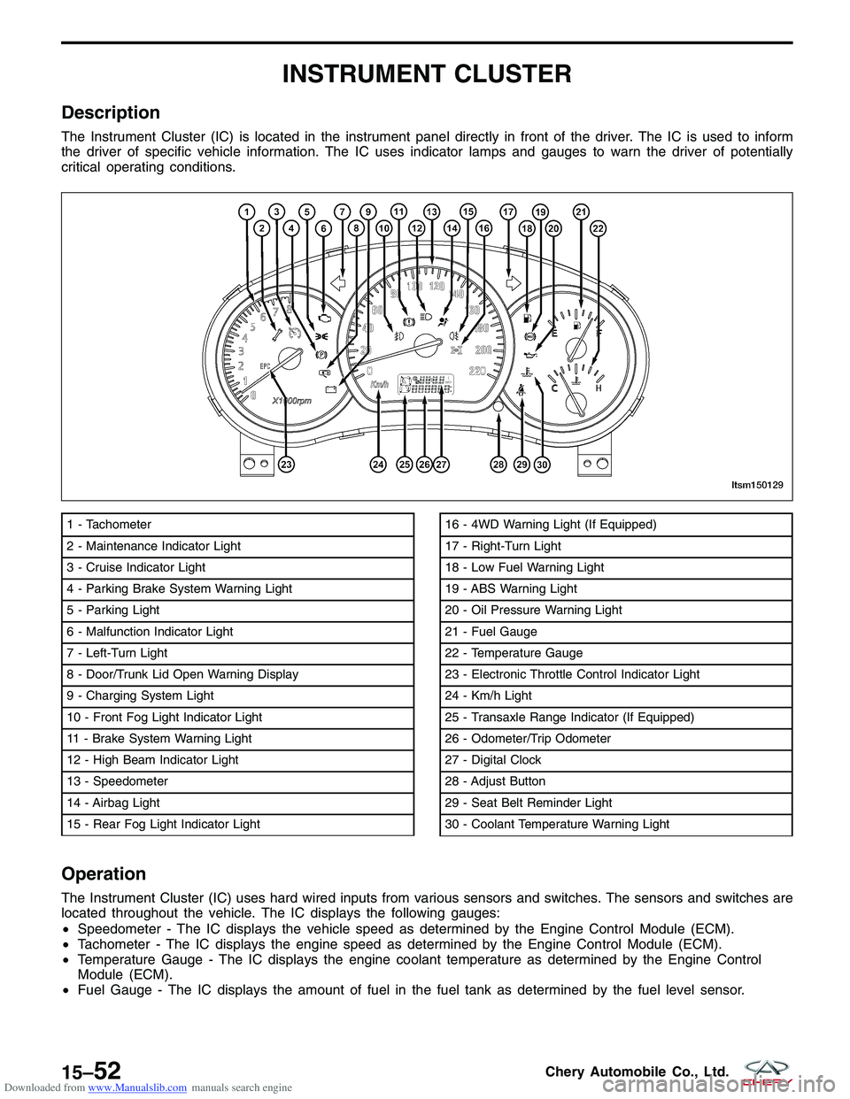
The Instrument Cluster (IC) is located in the instrument panel directly in front of the driver. The IC is used to inform
the driver of specific vehicle information. The IC uses indicator lamps and gauges to warn the driver of potentially
critical operating conditions.
Operation
The Instrument Cluster (IC) uses hard wired inputs from various sensors and switches. The sensors and switches are
located throughout the vehicle. The IC displays the following gauges:
•Speedometer - The IC displays the vehicle speed as determined by the Engine Control Module (ECM).
• Tachometer - The IC displays the engine speed as determined by the Engine Control Module (ECM).
• Temperature Gauge - The IC displays the engine coolant temperature as determined by the Engine Control
Module (ECM).
• Fuel Gauge - The IC displays the amount of fuel in the fuel tank as determined by the fuel level sensor.
1 - Tachometer
2 - Maintenance Indicator Light
3 - Cruise Indicator Light
4 - Parking Brake System Warning Light
5 - Parking Light
6 - Malfunction Indicator Light
7 - Left-Turn Light
8 - Door/Trunk Lid Open Warning Display
9 - Charging System Light
10 - Front Fog Light Indicator Light
11 - Brake System Warning Light
12 - High Beam Indicator Light
13 - Speedometer
14 - Airbag Light
15 - Rear Fog Light Indicator Light16 - 4WD Warning Light (If Equipped)
17 - Right-Turn Light
18 - Low Fuel Warning Light
19 - ABS Warning Light
20 - Oil Pressure Warning Light
21 - Fuel Gauge
22 - Temperature Gauge
23 - Electronic Throttle Control Indicator Light
24 - Km/h Light
25 - Transaxle Range Indicator (If Equipped)
26 - Odometer/Trip Odometer
27 - Digital Clock
28 - Adjust Button
29 - Seat Belt Reminder Light
30 - Coolant Temperature Warning Light
LTSM150129
15–52Chery Automobile Co., Ltd.
Page 1762 of 1903

Downloaded from www.Manualslib.com manuals search engine EXTERIOR LAMPS
Description
The exterior lamps consist of the following:
•Headlamps
• Rear Combination Lamps
• Side Repeater Lamps
• Fog Lamps
• Stop Lamps
• Backup Lamps
Operation
•Front Combination Lamp: With the light switch in the 2nd position, the Body Control Module (BCM) receives
input requesting head lamp operation. The BCM then supplies power to the head lamps.
• Turn Signal Lamp: When the turn signal switch is in LH or RH position with the ignition switch in the ON posi-
tion, the FBCM detects the RH or LH turn signal request. The BCM supplies power to the respective turn signal
lamp.
• Hazard Lamp: When the hazard switch is in the ON position, the BCM detects the hazard switch signal. The
BCM outputs the flasher signal (right and left). The BCM then activates the hazard indicator and audible
buzzer.
• Fog Lamp: When the front/rear fog lamp switch is in the ON position and also the light switch is in the 1st or
2nd position. The BCM receives input requesting fog lamp operation. The BCM then supplies power to the fog
lamps.
• Stop Lamp: When the brake pedal is applied, the stop lamp switch sends the signal to the RBCM. The RBCM
then supplies power to the stop lamps.
• Backup Lamp: When the BCM receives the signal from the backup lamp switch, then the BCM supplies power
to the backup lamp.
Specification
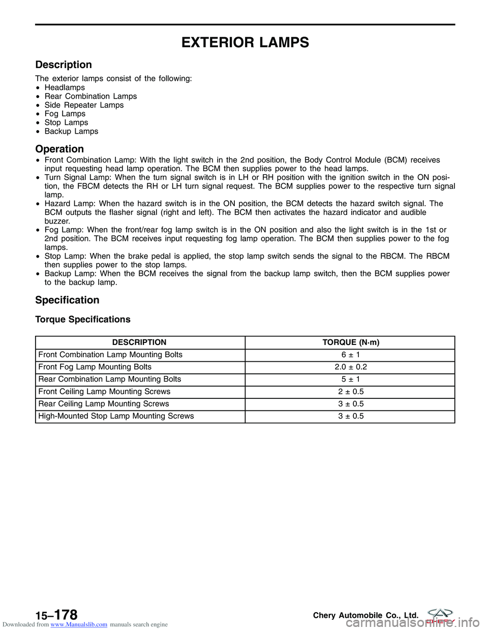
Torque Specifications
DESCRIPTION TORQUE (N·m)
Front Combination Lamp Mounting Bolts 6 ± 1
Front Fog Lamp Mounting Bolts 2.0 ± 0.2
Rear Combination Lamp Mounting Bolts 5 ± 1
Front Ceiling Lamp Mounting Screws 2 ± 0.5
Rear Ceiling Lamp Mounting Screws 3 ± 0.5
High-Mounted Stop Lamp Mounting Screws 3 ± 0.5
15–178Chery Automobile Co., Ltd.
Page 1885 of 1903

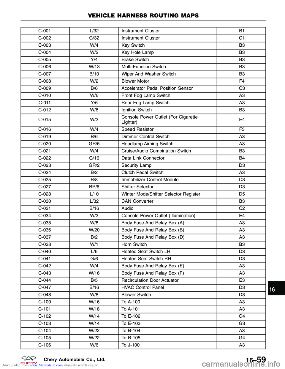
Downloaded from www.Manualslib.com manuals search engine C-001L/32 Instrument Cluster B1
C-002 G/32 Instrument Cluster C1
C-003 W/4 Key Switch B3
C-004 W/2 Key Hole Lamp B3
C-005 Y/4Brake Switch B3
C-006 W/13 Multi-Function Switch B3
C-007 B/10 Wiper And Washer Switch B3
C-008 W/2 Blower Motor F4
C-009 B/6Accelerator Pedal Position Sensor C3
C-010 W/6 Front Fog Lamp Switch A3
C-011 Y/6Rear Fog Lamp Switch A3
C-012 W/6 Ignition Switch B3
C-015 W/3Console Power Outlet (For Cigarette
Lighter) E4
C-016 W/4 Speed Resistor F3
C-019 B/6Dimmer Control Switch A3
C-020 GR/6 Headlamp Aiming Switch A3
C-021 W/4 Cruise/Audio Combination Switch B3
C-022 G/16 Data Link Connector B4
C-023 GR/2 Security Lamp D3
C-024 B/2Clutch Pedal Switch A3
C-025 B/8Immobilizer Control Module C3
C-027 BR/6 Shifter Selector D3
C-028 L/10 Winter Mode/Shifter Selector Register D5
C-030 L/32 CAN Converter B3
C-031 B/16 Audio C2
C-034 W/2 Console Power Outlet (Illumination) E4
C-035 W/8 Body Fuse And Relay Box (A) A3
C-036 W/20 Body Fuse And Relay Box (B) A3
C-037 B/2Body Fuse And Relay Box (D) A3
C-038 W/1 Horn Switch B3
C-040 L/6Heated Seat Switch LH D3
C-041 G/6Heated Seat Switch RH D3
C-042 W/4 Body Fuse And Relay Box (E) A3
C-043 W/16 Body Fuse And Relay Box (F) A3
C-044 B/5Recirculation Door Actuator E3
C-047 B/16 HVAC Control Panel D3
C-048 W/8 Blower Switch D3
C-100 W/16 To A-100 A3
C-101 W/18 To A-101 A3
C-102 W/14 To E-102 G4
C-103 W/14 To E-103 G3
C-104 W/22 To B-104 A3
C-105 W/22 To B-105 G4
C-106 W/6 To J-100 A3
VEHICLE HARNESS ROUTING MAPS
16
16–59Chery Automobile Co., Ltd.