2009 CHERY TIGGO brake
[x] Cancel search: brakePage 1518 of 1903
Downloaded from www.Manualslib.com manuals search engine 12. If the noise is from liquid refrigerant slugging in the A/C suction line, replace the A/C accumulator and check therefrigerant oil level and the refrigerant system charge.
13. If a slugging condition still exists after replacing the A/C accumulator, replace the A/C compressor.
Refrigerant System Leaks
WARNING!
R-134a service equipment or vehicle A/C systems should not be pressure tested or leak tested with compressed
air. Mixture of air and R-134a can be combustible at elevated pressures. These mixtures are potentially danger-
ous and may result in fire or explosion causing property damage, personal injury or death. Avoid breathing A/C
refrigerant and lubricant vapor or mist. Exposure may irritate eyes, nose and throat. Use only approved service
equipment meeting SAE requirements to discharge an R-134a system. If accidental system discharge occurs,
ventilate work area before resuming service.
NOTE :
If the A/C refrigerant system charge is empty or low, a leak in the A/C system is likely. Inspect all A/C lines, fittings
and components for an oily residue. Oil residue can be an indicator of an A/C system leak location.
NOTE :
The only way to correctly determine if the refrigerant system is fully charged with R-134a is to completely evacuate
and recharge the A/C system.
Refrigerant System Empty
1. Evacuate the refrigerant system to the lowest degree of vacuum possible. Determine if the system holds a vac- uum for 15 minutes. If vacuum is held, a leak is probably not present. If system will not maintain vacuum level,
proceed to STEP 2.
2. Prepare and dispense 0.3 kilograms of R-134a refrigerant into the evacuated refrigerant system and proceed to STEP 1 of the System Low procedure.
Refrigerant System Low
1. Position the vehicle in a wind-free work area. This will aid in detecting small leaks.
2. Operate the heating-A/C system with the engine at idle under the following conditions for at least 5 minutes:Doors or windows open, transaxle in Park or Neutral with the parking brake set (depending on application), A/C-
Heater controls set to outside air, full cool, panel mode, high blower and with A/C compressor engaged.
3. Shut the vehicle Off and wait2-7minutes. Then use an electronic leak detector that is designed to detect R-134a refrigerant and search for leaks. Fittings, lines or components that appear to be oily usually indicate a
refrigerant leak. To inspect the A/C evaporator for leaks, insert the leak detector probe into the drain tube open-
ing or an air outlet. A dye for R-134a is available to aid in leak detection. Use only approved refrigerant dye.
CAUTION:
A leak detector only designed for R-12 refrigerant will not detect leaks in an R-134a refrigerant sys-
tem.
DIAGNOSIS & TESTING
13–36Chery Automobile Co., Ltd.
Page 1603 of 1903
Downloaded from www.Manualslib.com manuals search engine CHIME
Description
The chime is located in the Instrument Cluster (IC). The chime warning system is an audible notification to the driver.
The chime warning system is designed to alert the driver of a vehicle problem or condition.
Operation
The Instrument Cluster (IC) uses hard wired inputs from various sensors and switches to activate the chime. The
sensors and switches are located throughout the vehicle. The following conditions will cause the chime to operate:
•Turn signal on
• Hazard warning flashers on
• Seat belt unbuckled
• Low fuel level
• Low oil pressure
• Low brake fluid level
• Doors unlocked
CHIME
15
15–19Chery Automobile Co., Ltd.
Page 1636 of 1903
Downloaded from www.Manualslib.com manuals search engine INSTRUMENT CLUSTER
Description
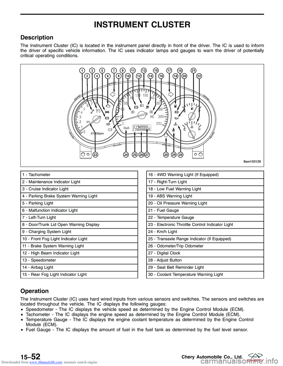
The Instrument Cluster (IC) is located in the instrument panel directly in front of the driver. The IC is used to inform
the driver of specific vehicle information. The IC uses indicator lamps and gauges to warn the driver of potentially
critical operating conditions.
Operation
The Instrument Cluster (IC) uses hard wired inputs from various sensors and switches. The sensors and switches are
located throughout the vehicle. The IC displays the following gauges:
•Speedometer - The IC displays the vehicle speed as determined by the Engine Control Module (ECM).
• Tachometer - The IC displays the engine speed as determined by the Engine Control Module (ECM).
• Temperature Gauge - The IC displays the engine coolant temperature as determined by the Engine Control
Module (ECM).
• Fuel Gauge - The IC displays the amount of fuel in the fuel tank as determined by the fuel level sensor.
1 - Tachometer
2 - Maintenance Indicator Light
3 - Cruise Indicator Light
4 - Parking Brake System Warning Light
5 - Parking Light
6 - Malfunction Indicator Light
7 - Left-Turn Light
8 - Door/Trunk Lid Open Warning Display
9 - Charging System Light
10 - Front Fog Light Indicator Light
11 - Brake System Warning Light
12 - High Beam Indicator Light
13 - Speedometer
14 - Airbag Light
15 - Rear Fog Light Indicator Light16 - 4WD Warning Light (If Equipped)
17 - Right-Turn Light
18 - Low Fuel Warning Light
19 - ABS Warning Light
20 - Oil Pressure Warning Light
21 - Fuel Gauge
22 - Temperature Gauge
23 - Electronic Throttle Control Indicator Light
24 - Km/h Light
25 - Transaxle Range Indicator (If Equipped)
26 - Odometer/Trip Odometer
27 - Digital Clock
28 - Adjust Button
29 - Seat Belt Reminder Light
30 - Coolant Temperature Warning Light
LTSM150129
15–52Chery Automobile Co., Ltd.
Page 1646 of 1903
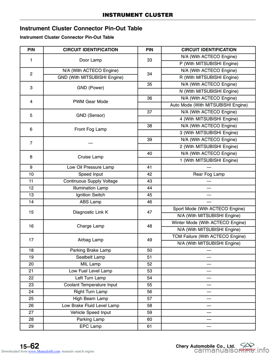
Downloaded from www.Manualslib.com manuals search engine Instrument Cluster Connector Pin-Out Table
Instrument Cluster Connector Pin-Out Table
PINCIRCUIT IDENTIFICATION PINCIRCUIT IDENTIFICATION
1 Door Lamp 33N/A (With ACTECO Engine)
P (With MITSUBISHI Engine)
2 N/A (With ACTECO Engine)
34N/A (With ACTECO Engine)
GND (With MITSUBISHI Engine) R (With MITSUBISHI Engine)
3 GND (Power) 35
N/A (With ACTECO Engine)
N (With MITSUBISHI Engine)
4 PWM Gear Mode 36
N/A (With ACTECO Engine)
Auto Mode (With MITSUBISHI Engine)
5 GND (Sensor) 37
N/A (With ACTECO Engine)
4 (With MITSUBISHI Engine)
6 Front Fog Lamp 38
N/A (With ACTECO Engine)
3 (With MITSUBISHI Engine)
7— 39
N/A (With ACTECO Engine)
2 (With MITSUBISHI Engine)
8 Cruise Lamp 40
N/A (With ACTECO Engine)
1 (With MITSUBISHI Engine)
9 Low Oil Pressure Lamp 41—
10 Speed Input 42Rear Fog Lamp
11 Continuous Supply Voltage 43—
12 Illumination Lamp 44—
13 Ignition Switch 45—
14 ABS Lamp 46—
15 Diagnostic Link K 47Sport Mode (With ACTECO Engine)
N/A (With MITSUBISHI Engine)
16 Charge Lamp 48Winter Mode (With ACTECO Engine)
N/A (With MITSUBISHI Engine)
17 Airbag Lamp 49TCM Failure (With ACTECO Engine)
N/A (With MITSUBISHI Engine)
18 Parking Brake Lamp 50—
19 Seatbelt Lamp 51—
20 MIL Lamp 52—
21 Low Fuel Level Lamp 53—
22 Left Turn Lamp 54—
23 Coolant Temperature Input 55—
24 Right Turn Lamp 56—
25 High Beam Lamp 57—
26 Low Brake Fluid Level Lamp 58—
27 Vehicle Speed Input 59—
28 Parking Lamp 60—
29 EPC Lamp 61—
INSTRUMENT CLUSTER
15–62Chery Automobile Co., Ltd.
Page 1762 of 1903
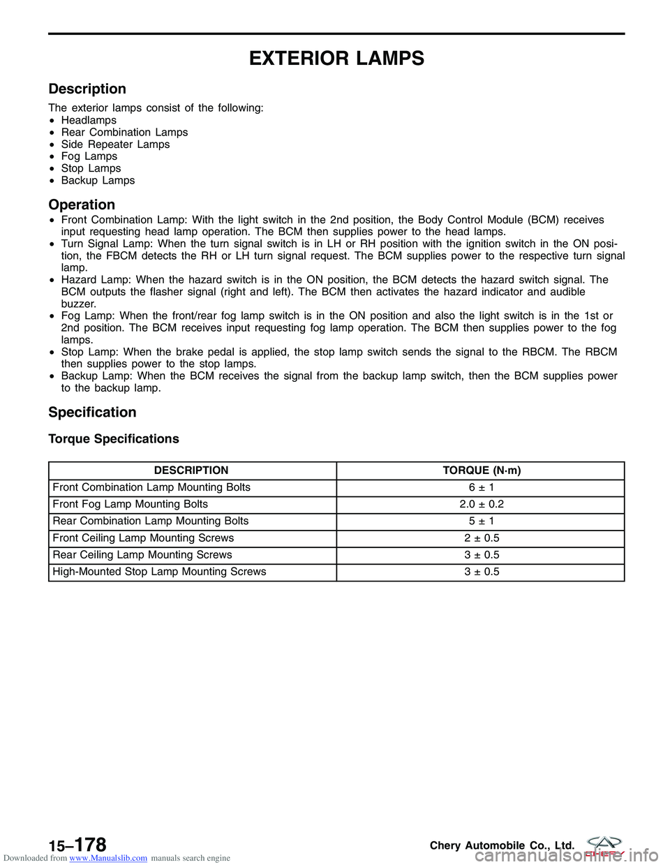
Downloaded from www.Manualslib.com manuals search engine EXTERIOR LAMPS
Description
The exterior lamps consist of the following:
•Headlamps
• Rear Combination Lamps
• Side Repeater Lamps
• Fog Lamps
• Stop Lamps
• Backup Lamps
Operation
•Front Combination Lamp: With the light switch in the 2nd position, the Body Control Module (BCM) receives
input requesting head lamp operation. The BCM then supplies power to the head lamps.
• Turn Signal Lamp: When the turn signal switch is in LH or RH position with the ignition switch in the ON posi-
tion, the FBCM detects the RH or LH turn signal request. The BCM supplies power to the respective turn signal
lamp.
• Hazard Lamp: When the hazard switch is in the ON position, the BCM detects the hazard switch signal. The
BCM outputs the flasher signal (right and left). The BCM then activates the hazard indicator and audible
buzzer.
• Fog Lamp: When the front/rear fog lamp switch is in the ON position and also the light switch is in the 1st or
2nd position. The BCM receives input requesting fog lamp operation. The BCM then supplies power to the fog
lamps.
• Stop Lamp: When the brake pedal is applied, the stop lamp switch sends the signal to the RBCM. The RBCM
then supplies power to the stop lamps.
• Backup Lamp: When the BCM receives the signal from the backup lamp switch, then the BCM supplies power
to the backup lamp.
Specification
Torque Specifications
DESCRIPTION TORQUE (N·m)
Front Combination Lamp Mounting Bolts 6 ± 1
Front Fog Lamp Mounting Bolts 2.0 ± 0.2
Rear Combination Lamp Mounting Bolts 5 ± 1
Front Ceiling Lamp Mounting Screws 2 ± 0.5
Rear Ceiling Lamp Mounting Screws 3 ± 0.5
High-Mounted Stop Lamp Mounting Screws 3 ± 0.5
15–178Chery Automobile Co., Ltd.
Page 1875 of 1903
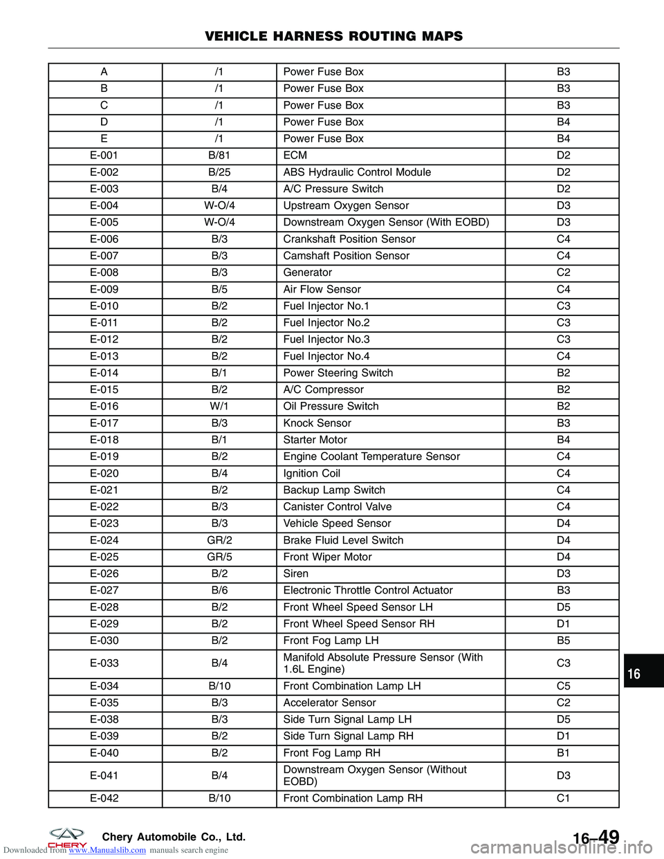
Downloaded from www.Manualslib.com manuals search engine A/1Power Fuse Box B3
B /1Power Fuse Box B3
C /1Power Fuse Box B3
D /1Power Fuse Box B4
E /1Power Fuse Box B4
E-001 B/81 ECM D2
E-002 B/25 ABS Hydraulic Control Module D2
E-003 B/4A/C Pressure Switch D2
E-004 W-O/4 Upstream Oxygen Sensor D3
E-005 W-O/4 Downstream Oxygen Sensor (With EOBD) D3
E-006 B/3Crankshaft Position Sensor C4
E-007 B/3Camshaft Position Sensor C4
E-008 B/3Generator C2
E-009 B/5Air Flow Sensor C4
E-010 B/2Fuel Injector No.1 C3
E-011 B/2Fuel Injector No.2 C3
E-012 B/2Fuel Injector No.3 C3
E-013 B/2Fuel Injector No.4 C4
E-014 B/1Power Steering Switch B2
E-015 B/2A/C Compressor B2
E-016 W/1 Oil Pressure Switch B2
E-017 B/3Knock Sensor B3
E-018 B/1Starter Motor B4
E-019 B/2Engine Coolant Temperature Sensor C4
E-020 B/4Ignition Coil C4
E-021 B/2Backup Lamp Switch C4
E-022 B/3Canister Control Valve C4
E-023 B/3Vehicle Speed Sensor D4
E-024 GR/2 Brake Fluid Level Switch D4
E-025 GR/5 Front Wiper Motor D4
E-026 B/2Siren D3
E-027 B/6Electronic Throttle Control Actuator B3
E-028 B/2Front Wheel Speed Sensor LH D5
E-029 B/2Front Wheel Speed Sensor RH D1
E-030 B/2Front Fog Lamp LH B5
E-033 B/4Manifold Absolute Pressure Sensor (With
1.6L Engine) C3
E-034 B/10 Front Combination Lamp LH C5
E-035 B/3Accelerator Sensor C2
E-038 B/3Side Turn Signal Lamp LH D5
E-039 B/2Side Turn Signal Lamp RH D1
E-040 B/2Front Fog Lamp RH B1
E-041 B/4Downstream Oxygen Sensor (Without
EOBD) D3
E-042 B/10 Front Combination Lamp RH C1
VEHICLE HARNESS ROUTING MAPS
16
16–49Chery Automobile Co., Ltd.
Page 1882 of 1903
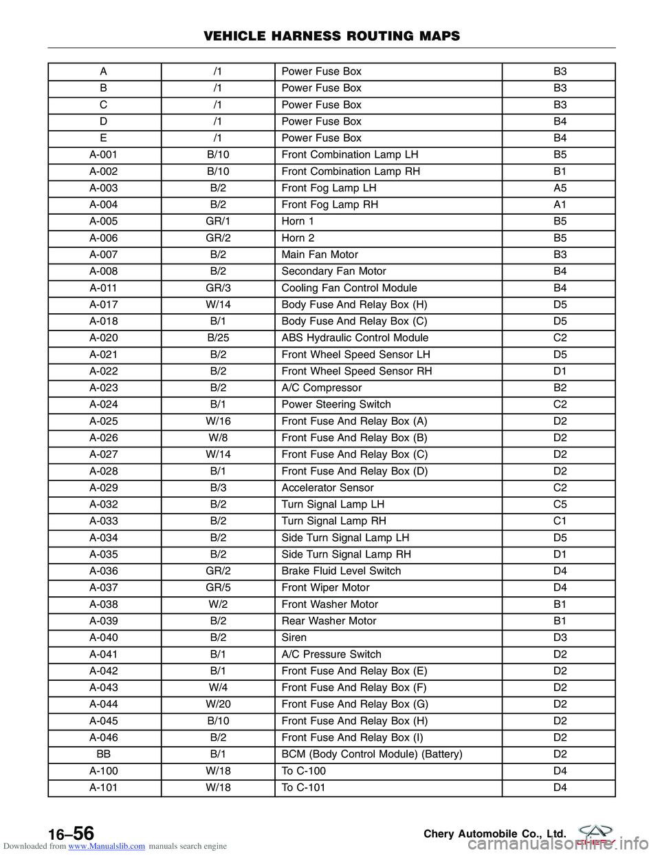
Downloaded from www.Manualslib.com manuals search engine A/1Power Fuse Box B3
B /1Power Fuse Box B3
C /1Power Fuse Box B3
D /1Power Fuse Box B4
E /1Power Fuse Box B4
A-001 B/10 Front Combination Lamp LH B5
A-002 B/10 Front Combination Lamp RH B1
A-003 B/2Front Fog Lamp LH A5
A-004 B/2Front Fog Lamp RH A1
A-005 GR/1 Horn 1 B5
A-006 GR/2 Horn 2 B5
A-007 B/2Main Fan Motor B3
A-008 B/2Secondary Fan Motor B4
A-011 GR/3 Cooling Fan Control Module B4
A-017 W/14 Body Fuse And Relay Box (H) D5
A-018 B/1Body Fuse And Relay Box (C) D5
A-020 B/25 ABS Hydraulic Control Module C2
A-021 B/2Front Wheel Speed Sensor LH D5
A-022 B/2Front Wheel Speed Sensor RH D1
A-023 B/2A/C Compressor B2
A-024 B/1Power Steering Switch C2
A-025 W/16 Front Fuse And Relay Box (A) D2
A-026 W/8 Front Fuse And Relay Box (B) D2
A-027 W/14 Front Fuse And Relay Box (C) D2
A-028 B/1Front Fuse And Relay Box (D) D2
A-029 B/3Accelerator Sensor C2
A-032 B/2Turn Signal Lamp LH C5
A-033 B/2Turn Signal Lamp RH C1
A-034 B/2Side Turn Signal Lamp LH D5
A-035 B/2Side Turn Signal Lamp RH D1
A-036 GR/2 Brake Fluid Level Switch D4
A-037 GR/5 Front Wiper Motor D4
A-038 W/2 Front Washer Motor B1
A-039 B/2Rear Washer Motor B1
A-040 B/2Siren D3
A-041 B/1A/C Pressure Switch D2
A-042 B/1Front Fuse And Relay Box (E) D2
A-043 W/4 Front Fuse And Relay Box (F) D2
A-044 W/20 Front Fuse And Relay Box (G) D2
A-045 B/10 Front Fuse And Relay Box (H) D2
A-046 B/2Front Fuse And Relay Box (I) D2
BB B/1BCM (Body Control Module) (Battery) D2
A-100 W/18 To C-100 D4
A-101 W/18 To C-101 D4
VEHICLE HARNESS ROUTING MAPS
16–56Chery Automobile Co., Ltd.
Page 1885 of 1903
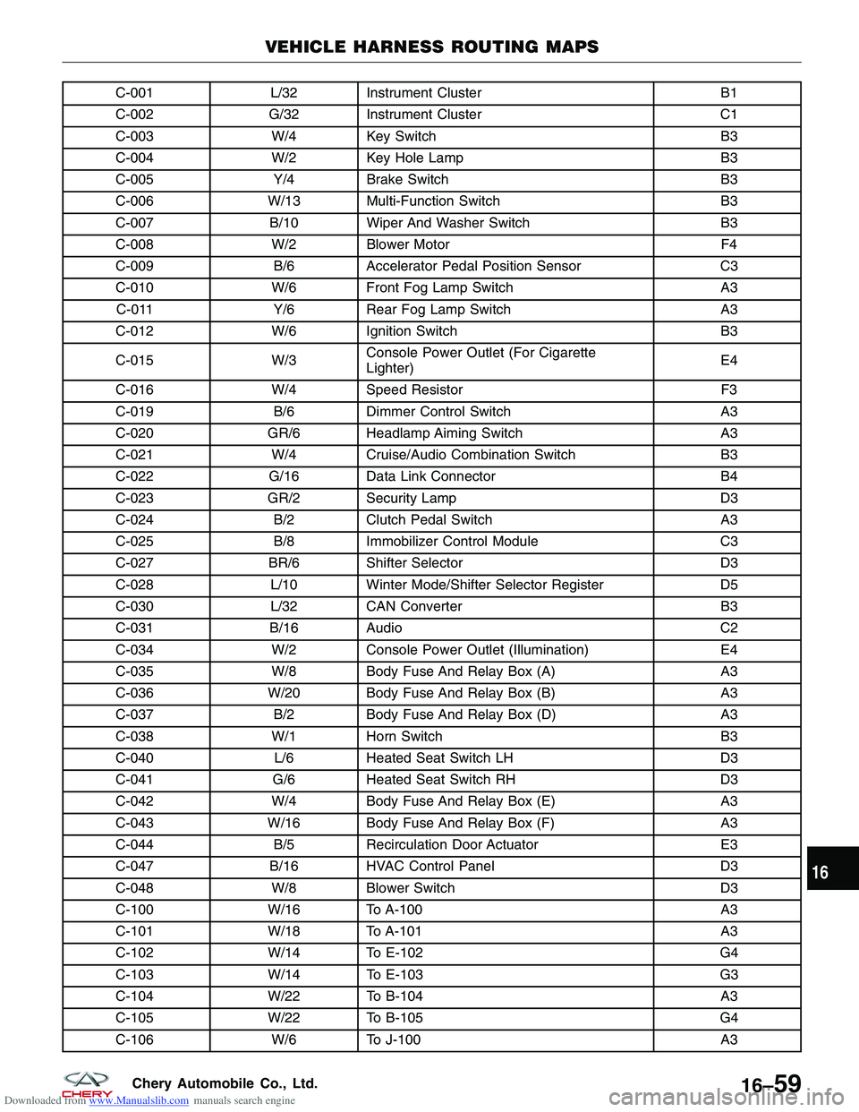
Downloaded from www.Manualslib.com manuals search engine C-001L/32 Instrument Cluster B1
C-002 G/32 Instrument Cluster C1
C-003 W/4 Key Switch B3
C-004 W/2 Key Hole Lamp B3
C-005 Y/4Brake Switch B3
C-006 W/13 Multi-Function Switch B3
C-007 B/10 Wiper And Washer Switch B3
C-008 W/2 Blower Motor F4
C-009 B/6Accelerator Pedal Position Sensor C3
C-010 W/6 Front Fog Lamp Switch A3
C-011 Y/6Rear Fog Lamp Switch A3
C-012 W/6 Ignition Switch B3
C-015 W/3Console Power Outlet (For Cigarette
Lighter) E4
C-016 W/4 Speed Resistor F3
C-019 B/6Dimmer Control Switch A3
C-020 GR/6 Headlamp Aiming Switch A3
C-021 W/4 Cruise/Audio Combination Switch B3
C-022 G/16 Data Link Connector B4
C-023 GR/2 Security Lamp D3
C-024 B/2Clutch Pedal Switch A3
C-025 B/8Immobilizer Control Module C3
C-027 BR/6 Shifter Selector D3
C-028 L/10 Winter Mode/Shifter Selector Register D5
C-030 L/32 CAN Converter B3
C-031 B/16 Audio C2
C-034 W/2 Console Power Outlet (Illumination) E4
C-035 W/8 Body Fuse And Relay Box (A) A3
C-036 W/20 Body Fuse And Relay Box (B) A3
C-037 B/2Body Fuse And Relay Box (D) A3
C-038 W/1 Horn Switch B3
C-040 L/6Heated Seat Switch LH D3
C-041 G/6Heated Seat Switch RH D3
C-042 W/4 Body Fuse And Relay Box (E) A3
C-043 W/16 Body Fuse And Relay Box (F) A3
C-044 B/5Recirculation Door Actuator E3
C-047 B/16 HVAC Control Panel D3
C-048 W/8 Blower Switch D3
C-100 W/16 To A-100 A3
C-101 W/18 To A-101 A3
C-102 W/14 To E-102 G4
C-103 W/14 To E-103 G3
C-104 W/22 To B-104 A3
C-105 W/22 To B-105 G4
C-106 W/6 To J-100 A3
VEHICLE HARNESS ROUTING MAPS
16
16–59Chery Automobile Co., Ltd.