Page 1217 of 1903

Downloaded from www.Manualslib.com manuals search engine Inspection
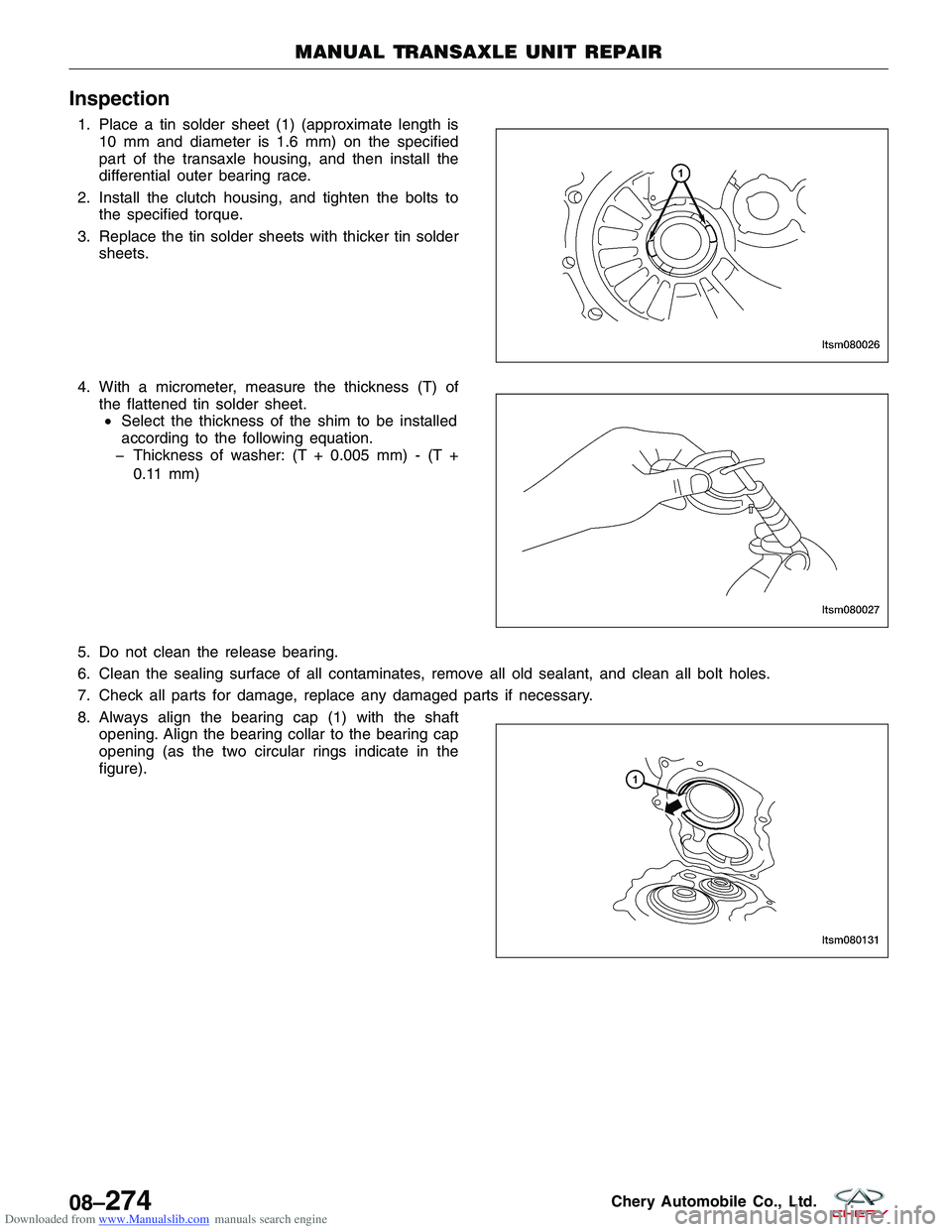
1. Place a tin solder sheet (1) (approximate length is10 mm and diameter is 1.6 mm) on the specified
part of the transaxle housing, and then install the
differential outer bearing race.
2. Install the clutch housing, and tighten the bolts to the specified torque.
3. Replace the tin solder sheets with thicker tin solder sheets.
4. With a micrometer, measure the thickness (T) of the flattened tin solder sheet.• Select the thickness of the shim to be installed
according to the following equation.
� Thickness of washer: (T + 0.005 mm) - (T +
0.11 mm)
5. Do not clean the release bearing.
6. Clean the sealing surface of all contaminates, remove all old sealant, and clean all bolt holes.
7. Check all parts for damage, replace any damaged parts if necessary.
8. Always align the bearing cap (1) with the shaft opening. Align the bearing collar to the bearing cap
opening (as the two circular rings indicate in the
figure).
MANUAL TRANSAXLE UNIT REPAIR
LTSM080026
LTSM080027
LTSM080131
08–274Chery Automobile Co., Ltd.
Page 1218 of 1903
Downloaded from www.Manualslib.com manuals search engine 9. Place the transaxle in the neutral position wheninstalling the self-locking bolts for the gear posi-
tions. The notches (1) of the shift fork guide block
should align in the same line.
10. Place the transaxle in the neutral position (1) when the gear shift mechanism housing assemble is in
the position of the selector finger in the gear shift
mechanism housing assembly shown in the figure.
11. Alternate tightening each bolt to the specified torque.
Assembly
1. Install the input shaft together with the output shaft.
2. Install the 5th-reverse gear shifting fork/fork stalk-5th-reverse gear fork/3rd-4th gear shifting fork/fork stalk–3rd- 4th fork.
3. Move the gear bushing-3rd-4th gear (1) and the gear bushing-5th-reverse gear (2) in the direction
shown in the figure.
MANUAL TRANSAXLE UNIT REPAIR
LTSM080132
LTSM080133
LTSM080028
08
08–275Chery Automobile Co., Ltd.
Page 1219 of 1903
Downloaded from www.Manualslib.com manuals search engine 4. Install the 3rd-4th gear shifting fork (2) and its forkstalk (1) and the 5th-reverse gear shifting fork (3)
and its stalk (4).
5. Install all gear shifting forks into the gear hub, and at the same time, move the fork stalks (1) & (2) in
the direction shown in the figure.
6. Install the locking pin.
7. Using special tools MB-990938 (1) and MB-990935 (2), install the outer bearing race.
MANUAL TRANSAXLE UNIT REPAIR
LTSM080029
LTSM080024
LTSM080030
LTSM080031
08–276Chery Automobile Co., Ltd.
Page 1220 of 1903
Downloaded from www.Manualslib.com manuals search engine 8. Install the transaxle housing.
9. Applya1mmto1.2mmdiameter of sealant onthe specified position of the transaxle housing.
CAUTION:
The sealant line applied should be uniform and
continuous and without breaks.
10. Tighten the transaxle housing bolts to the specified torque.
11. Install the bottom transaxle cover.
12. Applya1mmto1.2mmdiameter of sealant on the specified position of the transaxle housing.
CAUTION:
The sealant line applied should be uniform and
continuous and without breaks.
13. Apply transaxle fluid to the O-ring of speed sensor.(Transaxle fluid: 75W-90)
MANUAL TRANSAXLE UNIT REPAIR
LTSM080032
LTSM080033
LTSM080034
08
08–277Chery Automobile Co., Ltd.
Page 1221 of 1903
Downloaded from www.Manualslib.com manuals search engine 14. Install the vehicle speed sensor.
15. Install the gear shifting arm assembly. Apply lubri-cating fluid on the contact surface of the gear shift-
ing drive slider and the gear shifting arm assembly.
(The specified lubricating fluid: Mobilux Ep2)
STATUS OF SWITCH CIRCUIT
Pressed Off
Released On
16. Inspect the backup lamp switch. Inspect the switch for broken terminal or an open circuit.
Input Shaft
Specifications
Clearance Specifications
SYNCHRONIZER RING VALUE OF A (mm)WEARING LIMIT
1st-2nd Gear 1.10 - 1.170.05 mm
3rd-4th Gear 1.35 - 1.900.05 mm
5th Gear 1.10 - 1.170.05 mm
MANUAL TRANSAXLE UNIT REPAIR
LTSM080035
LTSM080036
08–278Chery Automobile Co., Ltd.
Page 1222 of 1903
Downloaded from www.Manualslib.com manuals search engine Disassemble
1 - Input Shaft
2 - Input Shaft Front Bearing
3 - Snap Ring
4 - Needle Bearing-3rd Gear
5 - 3rd Driving Gear Assembly
6 - Synchronizer Ring-3rd-4th Gear
7 - Gear Hub-3rd-4th Gear
8 - Guide Block
9 - Spring-3rd-4th Gear Synchronizer
10 - Hub Sleeve-3rd-4th Gear11 - Gear Bushing-4th Gear
12 - Needle Bearing-2nd-4th Gear
13 - 4th Driving Gear Assembly
14 - 5th Driving Gear
15 - Thrust Ring-5th Driving Gear
16 - Clip-5th Driving Gear Thrust Plate
17 - Input Shaft Rear Bearing
18 - Snap Ring-Input Shaft Rear Bearing
19 - Seal-Input Shaft Fluid-Collecting Hole
MANUAL TRANSAXLE UNIT REPAIR
LTSM080037
08
08–279Chery Automobile Co., Ltd.
Page 1223 of 1903
Downloaded from www.Manualslib.com manuals search engine NOTE :
The following special tools are required to perform the repair procedure:
•MB-998801 - Bearings Remover
• MB-998812 - Installer Cap
• MB-998813 - Installer (100 mm)
• MB-998816 - Installer Connector (30 mm)
• MB-998825 - Installer Connector (52 mm)
• MB-998824 - Installer Connector (50 mm)
1. Using special tool MB-998801 (1), disassemble the input shaft rear bearing.
2. Using special tool MB-998801 (1), disassemble the 5th driving gear.
3. Disassemble the sleeve-4th gear. Mount special tool MB-998801 (1) on the 3rd driv-
ing gear to disassemble the sleeve-4th gear.
MANUAL TRANSAXLE UNIT REPAIR
LTSM080038
LTSM080039
LTSM080040
08–280Chery Automobile Co., Ltd.
Page 1224 of 1903
Downloaded from www.Manualslib.com manuals search engine 4. Using special tool MB-998801 (1), disassemble theinput shaft front bearing.
Assemble
1. Install the input shaft seal.Press the seal in until the dimension shown in the
figure is obtained.
2. Using special tools MB-998801 (4), MB-998812 (1), MB-998813 (2) and MB-998816 (3), install the
input shaft front bearing.
3. Install the input shaft front shaft snap ring. Select a snap ring to maintain the axial clearance
standard.
(The standard value: 0.01 mm - 0.12 mm)
MANUAL TRANSAXLE UNIT REPAIR
LTSM080041
LTSM080042
LTSM080043
LTSM080044
08
08–281Chery Automobile Co., Ltd.