Page 55 of 84

PERIODIC MAINTENANCE AND MINOR REPAIR
6-23
6 4. If the drive chain slack is incorrect,
adjust it as follows.
EAU34312
To adjust the drive chain slack
1. Loosen the axle nut and the lock-
nut on each side of the swingarm.2. To tighten the drive chain, turn the
drive chain slack adjusting bolt on
each side of the swingarm in direc-
tion (a). To loosen the drive chain,
turn the adjusting bolt on each side
of the swingarm in direction (b),
and then push the rear wheel for-
ward.
NOTE:Using the alignment marks on each
side of the swingarm, make sure that
both chain pullers are in the same posi-tion for proper wheel alignment.
CAUTION:
ECA10570
Improper drive chain slack will over-
load the engine as well as other vital
parts of the motorcycle and can lead
to chain slippage or breakage. To
prevent this from occurring, keep
the drive chain slack within thespecified limits.
3. Tighten the locknuts, then the axle
nut to their specified torques.
1. Drive chain slack
1. Axle nut
2. Drive chain slack adjusting bolt
3. Locknut
4. Alignment marks
Tightening torques:
Locknut:
16 Nm (1.6 m·kgf, 11 ft·lbf)
Axle nut:
85 Nm (8.5 m·kgf, 61 ft·lbf)
U5D7E0E0.book Page 23 Tuesday, December 18, 2007 10:13 AM
Page 66 of 84

PERIODIC MAINTENANCE AND MINOR REPAIR
6-34
66. Pull the wheel axle out, remove the
speed sensor by pulling it out, and
then remove the wheel.
CAUTION:
ECA11050
Do not apply the brake after the
brake calipers have been removed,
otherwise the brake pads will beforced shut.
EAUM2430
To install the front wheel
1. Lift the wheel up between the fork
legs.
2. Install the speed sensor at the
wheel hub.NOTE:Make sure that the projections on the
speed sensor rotor are aligned with the
notches in the wheel hub and that the
slot in the speed sensor fits over the re-tainer on the fork leg.
3. Insert the wheel axle.
4. Lower the front wheel so that it is
on the ground.
5. Push down hard on the handlebar
several times to check for proper
fork operation.
6. Install the brake caliper by install-
ing the bolts.
NOTE:Make sure that there is enough space
between the brake pads before install-
ing the brake caliper onto the brakedisc.
7. Install the brake hose holder by in-
stalling the bolt.
8. Install the speed sensor lead hold-
er by installing the bolt.
9. Tighten the wheel axle, front wheel
axle pinch bolt and brake caliper
bolts to the specified torques.
1. Brake hose holder
2. Brake caliper bolt
3. Brake caliper
4. Axle bolt
1. Speedometer gear unit
Tightening torques:
Wheel axle:
59 Nm (5.9 m·kgf, 43 ft·lbf)
Front wheel axle pinch bolt:
14 Nm (1.4 m·kgf, 10 ft·lbf)
Brake caliper bolt:
30 Nm (3.0 m·kgf, 22 ft·lbf)
U5D7E0E0.book Page 34 Tuesday, December 18, 2007 10:13 AM
Page 68 of 84

PERIODIC MAINTENANCE AND MINOR REPAIR
6-36
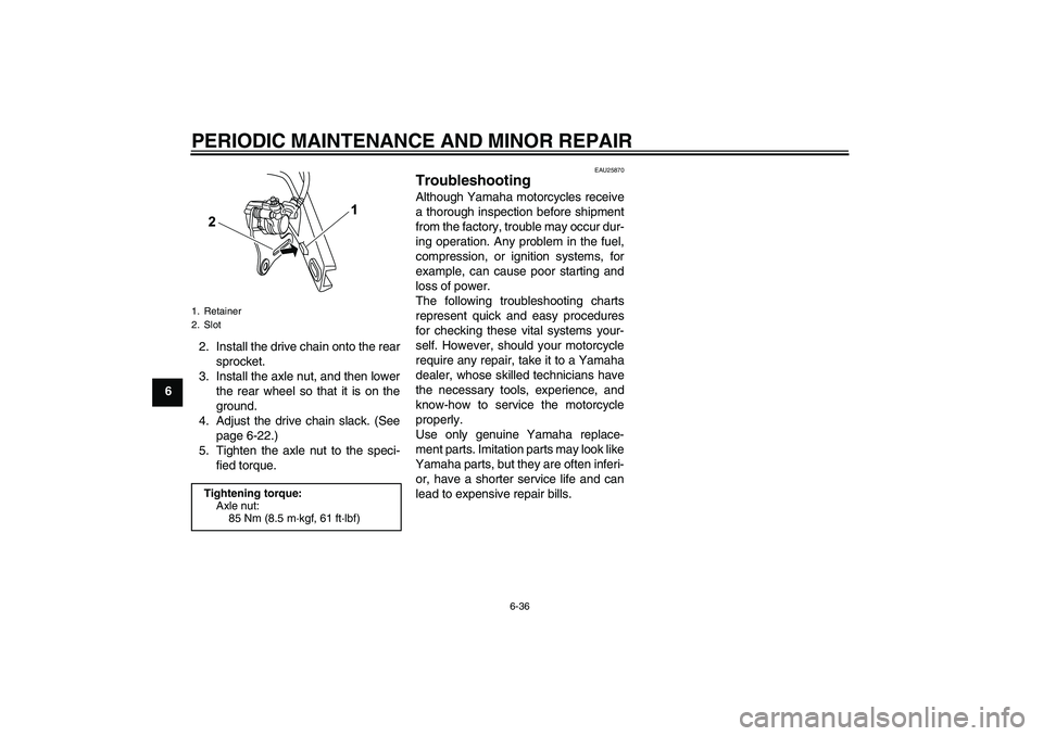
62. Install the drive chain onto the rear
sprocket.
3. Install the axle nut, and then lower
the rear wheel so that it is on the
ground.
4. Adjust the drive chain slack. (See
page 6-22.)
5. Tighten the axle nut to the speci-
fied torque.
EAU25870
Troubleshooting Although Yamaha motorcycles receive
a thorough inspection before shipment
from the factory, trouble may occur dur-
ing operation. Any problem in the fuel,
compression, or ignition systems, for
example, can cause poor starting and
loss of power.
The following troubleshooting charts
represent quick and easy procedures
for checking these vital systems your-
self. However, should your motorcycle
require any repair, take it to a Yamaha
dealer, whose skilled technicians have
the necessary tools, experience, and
know-how to service the motorcycle
properly.
Use only genuine Yamaha replace-
ment parts. Imitation parts may look like
Yamaha parts, but they are often inferi-
or, have a shorter service life and can
lead to expensive repair bills.
1. Retainer
2. SlotTightening torque:
Axle nut:
85 Nm (8.5 m·kgf, 61 ft·lbf)
U5D7E0E0.book Page 36 Tuesday, December 18, 2007 10:13 AM