Page 49 of 106

PERIODIC MAINTENANCE AND MINOR REPAIR
6-1
6
EAU17240
Safety is an obligation of the owner. Pe-
riodic inspection, adjustment and lubri-
cation will keep your vehicle in the
safest and most efficient condition pos-
sible. The most important points of in-
spection, adjustment, and lubrication
are explained on the following pages.
The intervals given in the periodic
maintenance and lubrication chart
should be simply considered as a gen-
eral guide under normal riding condi-
tions. However, DEPENDING ON THE
WEATHER, TERRAIN, GEOGRAPHI-
CAL LOCATION, AND INDIVIDUAL
USE, THE MAINTENANCE INTER-
VALS MAY NEED TO BE SHORT-
ENED.
WARNING
EWA10320
If you are not familiar with mainte-
nance work, have a Yamaha dealerdo it for you.
EAU33881
Owner’s tool kit The owner’s tool kit is located under the
passenger seat. (See page 3-19.)
The service information included in this
manual and the tools provided in the
owner’s tool kit are intended to assist
you in the performance of preventive
maintenance and minor repairs. How-
ever, additional tools such as a torque
wrench may be necessary to perform
certain maintenance work correctly.NOTE:If you do not have the tools or experi-
ence required for a particular job, havea Yamaha dealer perform it for you.
WARNING
EWA10350
Modifications not approved by
Yamaha may cause loss of perfor-
mance and render the vehicle un-
safe for use. Consult a Yamaha
dealer before attempting any chang-es.
WARNING
EWA12371
Do not touch either muffler bracket,
located under the muffler bracket
covers, until the exhaust system hascooled.
1. Owner’s tool kit
1. Muffler bracket cover
2. Muffler bracket
U4C8E1E0.book Page 1 Wednesday, June 13, 2007 9:24 AM
Page 50 of 106

PERIODIC MAINTENANCE AND MINOR REPAIR
6-2
6
EAU17709
Periodic maintenance and lubrication chart NOTE:�
The annual checks must be performed every year, except if a kilometer-based maintenance is performed in-
stead.
�
From 50000 km, repeat the maintenance intervals starting from 10000 km.
�
Items marked with an asterisk should be performed by a Yamaha dealer as they require special tools, data and technicalskills.
NO. ITEM CHECK OR MAINTENANCE JOBODOMETER READING (× 1000 km)
ANNUAL
CHECK
1 10203040
1*Fuel lineCheck fuel hoses for cracks or damage.√√√√ √
2*Spark plugsCheck condition.
Clean and regap.√√
Replace.√√
3*ValvesCheck valve clearance.
Adjust.Every 40000 km
4 Air filter elementReplace.√
5ClutchCheck operation.
Adjust.√√√√√
6*Front brakeCheck operation, fluid level and vehicle for fluid leakage.√√√√√ √
Replace brake pads. Whenever worn to the limit
7*Rear brakeCheck operation, fluid level and vehicle for fluid leakage.√√√√√ √
Replace brake pads. Whenever worn to the limit
8*Brake hosesCheck for cracks or damage.√√√√ √
Replace. Every 4 years
9*WheelsCheck runout and for damage.√√√√
U4C8E1E0.book Page 2 Wednesday, June 13, 2007 9:24 AM
Page 51 of 106

PERIODIC MAINTENANCE AND MINOR REPAIR
6-3
6
10*TiresCheck tread depth and for damage.
Replace if necessary.
Check air pressure.
Correct if necessary.√√√√ √
11*Wheel bearingsCheck bearing for looseness or damage.√√√√
12*SwingarmCheck operation and for excessive play.√√√√
Lubricate with lithium-soap-based grease. Every 50000 km
13 Drive chainCheck chain slack, alignment and condition.
Adjust and lubricate chain with a special O-ring chain lu-
bricant thoroughly. Every 800 km and after washing the motorcycle or
riding in the rain
14*Steering bearingsCheck bearing play and steering for roughness.√√√√√
Lubricate with lithium-soap-based grease. Every 20000 km
15*Steering damperCheck operation and for oil leakage.√√√√
16*Chassis fastenersMake sure that all nuts, bolts and screws are properly
tightened.√√√√ √
17 Brake lever pivot shaftLubricate with silicone grease.√√√√ √
18 Clutch lever pivot shaftLubricate with lithium-soap-based grease.√√√√ √
19 Shift pedal rod pivotsLubricate with lithium-soap-based grease.√√√√ √
20 SidestandCheck operation.
Lubricate.√√√√ √
21*Sidestand switchCheck operation.√√√√√ √
22*Front forkCheck operation and for oil leakage.√√√√
23*Shock absorber assem-
blyCheck operation and shock absorber for oil leakage.√√√√ NO. ITEM CHECK OR MAINTENANCE JOBODOMETER READING (× 1000 km)
ANNUAL
CHECK
1 10203040
U4C8E1E0.book Page 3 Wednesday, June 13, 2007 9:24 AM
Page 52 of 106

PERIODIC MAINTENANCE AND MINOR REPAIR
6-4
6
24*Rear suspension relay
arm and connecting
arm pivoting pointsCheck operation.√√√√
25*Fuel injection systemAdjust synchronization.√√√√ √
26 Engine oilChange.
Check oil level and vehicle for oil leakage.√√√√√ √
27Engine oil filter car-
tridgeReplace.√√√
28*Cooling systemCheck coolant level and vehicle for coolant leakage.√√√√ √
Change. Every 3 years
29*Front and rear brake
switchesCheck operation.√√√√√ √
30Moving parts and ca-
blesLubricate.√√√√ √
31*Throttle grip housing
and cableCheck operation and free play.
Adjust the throttle cable free play if necessary.
Lubricate the throttle grip housing and cable.√√√√ √
32*Air induction systemCheck the air cut-off valve, reed valve, and hose for dam-
age.
Replace any damaged parts if necessary.√√√√ √
33*Muffler and exhaust
pipeCheck the screw clamp for looseness.√√√√√
34*EXUP systemCheck operation, cable free play and pulley position.√√√
35*Lights, signals and
switchesCheck operation.
Adjust headlight beam.√√√√√ √ NO. ITEM CHECK OR MAINTENANCE JOBODOMETER READING (× 1000 km)
ANNUAL
CHECK
1 10203040U4C8E1E0.book Page 4 Wednesday, June 13, 2007 9:24 AM
Page 53 of 106
PERIODIC MAINTENANCE AND MINOR REPAIR
6-5
6
EAU18680
NOTE:�
Air filter
This model’s air filter is equipped with a disposable oil-coated paper element, which must not be cleaned with com-
pressed air to avoid damaging it.
The air filter element needs to be replaced more frequently when riding in unusually wet or dusty areas.
�
Hydraulic brake service
Regularly check and, if necessary, correct the brake fluid level.
Every two years replace the internal components of the brake master cylinders and calipers, and change the brake
fluid.Replace the brake hoses every four years and if cracked or damaged.
U4C8E1E0.book Page 5 Wednesday, June 13, 2007 9:24 AM
Page 54 of 106
PERIODIC MAINTENANCE AND MINOR REPAIR
6-6
6
EAU18712
Removing and installing cowl-
ings and panels The cowlings and panels shown need
to be removed to perform some of the
maintenance jobs described in this
chapter. Refer to this section each time
a cowling or panel needs to be re-
moved and installed.
EAU42970
Cowlings A and B
To remove one of the cowlings1. Remove the quick fastener screws
and the quick fasteners, slide the
cowling backward, and then take it
off.
1. Panel A
2. Panel C
3. Cowling A
4. Cowling C
1. Panel B
2. Panel D
3. Cowling B
1. Quick fastener screw
1. Cowling A
2. Quick fastener
U4C8E1E0.book Page 6 Wednesday, June 13, 2007 9:24 AM
Page 55 of 106
PERIODIC MAINTENANCE AND MINOR REPAIR
6-7
6 2. Disconnect the turn signal light
lead coupler.
To install the cowling
1. Connect the turn signal light lead
coupler.2. Fit the projections on the cowling
into the slots and slide it forward.
3. Install the quick fasteners and the
quick fastener screws.
EAU42951
Cowling C
To remove the cowling1. Remove cowling A. (See page
6-6.)
2. Remove the bolts and the quick
fastener screws.3. Slide the cowling backward to un-
hook its projections from the slots,
and then pull the cowling off.
1. Cowling B
2. Quick fastener
1. Turn signal light lead coupler
1. Slot
2. Projection
1. Bolt
2. Quick fastener screw
3. Cowling C
1. Cowling C
2. Slot
3. Projection
U4C8E1E0.book Page 7 Wednesday, June 13, 2007 9:24 AM
Page 56 of 106
PERIODIC MAINTENANCE AND MINOR REPAIR
6-8
6To install the cowling
1. Insert the projections into the slots,
and then slide the cowling forward.
2. Place the cowling in its original po-
sition, and then install the quick
fastener screws and the bolts.
3. Install cowling A.
EAU33990
Panels A and B
To remove one of the panels1. Remove the rider seat. (See page
3-19.)
2. Remove the screw, and then re-
move the panel as shown.To install the panel
1. Place the panel in its original posi-
tion, and then install the screw.
2. Install the rider seat.
EAU36630
Panels C and D
To remove one of the panelsRemove the screw and the quick fas-
tener, and then pull the panel off as
shown.
To install the panelPlace the panel in the original position,
and then install the screw and the quick
fastener.
1. Slot
2. Projection
1. Panel A
2. Screw
1. Screw
2. Panel C
3. Quick fastener
U4C8E1E0.book Page 8 Wednesday, June 13, 2007 9:24 AM
 1
1 2
2 3
3 4
4 5
5 6
6 7
7 8
8 9
9 10
10 11
11 12
12 13
13 14
14 15
15 16
16 17
17 18
18 19
19 20
20 21
21 22
22 23
23 24
24 25
25 26
26 27
27 28
28 29
29 30
30 31
31 32
32 33
33 34
34 35
35 36
36 37
37 38
38 39
39 40
40 41
41 42
42 43
43 44
44 45
45 46
46 47
47 48
48 49
49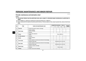 50
50 51
51 52
52 53
53 54
54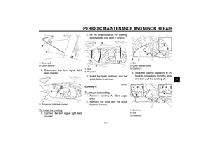 55
55 56
56 57
57 58
58 59
59 60
60 61
61 62
62 63
63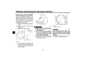 64
64 65
65 66
66 67
67 68
68 69
69 70
70 71
71 72
72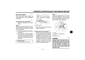 73
73 74
74 75
75 76
76 77
77 78
78 79
79 80
80 81
81 82
82 83
83 84
84 85
85 86
86 87
87 88
88 89
89 90
90 91
91 92
92 93
93 94
94 95
95 96
96 97
97 98
98 99
99 100
100 101
101 102
102 103
103 104
104 105
105


