Page 25 of 88

NOTE:
Even if the key is turned from “ON” to
“OFF” with the hazard lighting on, the
hazard lighting will continue to flash
regardless of the hazard switch posi-
tion. To cancel the hazard lighting, the
key must be turned to “ON” and the
hazard switch must be set to the “h”
position.
The hazard lighting is used in case of
an emergency or to warn other drivers
when your scooter is stopped where
it might be a traffic hazard.
ECA10060
CAUTION:
Do not use the hazard light for an
extended length of time, otherwise
the battery may discharge.
EAU12720
Start switch “g”
With the sidestand up, push this
switch while applying the front or rear
brake to crank the engine with the
starter.
ECA10050
CAUTION:
See page 5-1 for starting instruc-
tions prior to starting the engine.
EAU12900
Front brake lever
1. Front brake lever
The front brake lever is located on the
right handlebar grip. To apply the
front brake, pull this lever toward the
handlebar grip.
INSTRUMENT AND CONTROL FUNCTIONS
3-10
3
1B9-F8199-E2.qxd 13/11/07 12:18 Página 25
Page 26 of 88
EAU12950
Rear brake lever
1. Rear brake lever
The rear brake lever is located on the
left handlebar grip. To apply the rear
brake, pull this lever toward the hand-
lebar grip.
EAUT1382
Fuel tank cap
To remove the fuel tank cap
Open the lid by pulling the lever up.
1. Push
1. Open the lid
Insert the key into the fuel tank cap
lock and turn it 1/4 turn counterclock-
wise. The lock will be released and
the fuel tank cap can be removed.
1. Open the fuel tank cap
NOTE:
After removing the fuel tank cap, pla-
ce it into the fuel tank cap holder as
shown.
To install the fuel tank cap
1. Insert the fuel tank cap into the
fuel tank opening with the key
inserted in the lock and the
match marks aligned.
2. Turn the key clockwise to the ori-
ginal position, and then remove
it.
INSTRUMENT AND CONTROL FUNCTIONS
3-11
3
1B9-F8199-E2.qxd 13/11/07 12:18 Página 26
Page 27 of 88
1. Close the fuel tank cap
NOTE:
The fuel tank cap cannot be installed
unless the key is in the lock. In addi-
tion, the key cannot be removed if the
cap is not properly installed and loc-
ked.
3. Close the lid.
1. Close the lid
EWA10130
s s
WARNING
Make sure that the fuel tank cap is
properly installed before riding.
EAU13211
Fuel
Make sure that there is sufficient fuel
in the tank. Fill the fuel tank to the
bottom of the filler tube as shown.
1. Fuel tank filler tube
2. Fuel level
EWA10880
s s
WARNING
●Do not overfill the fuel tank,
otherwise it may overflow
when the fuel warms up and
expands.
●Avoid spilling fuel on the hot
engine.
INSTRUMENT AND CONTROL FUNCTIONS
3-12
3
1B9-F8199-E2.qxd 13/11/07 12:18 Página 27
Page 28 of 88

ECA10070
CAUTION:
Immediately wipe off spilled fuel
with a clean, dry, soft cloth, since
fuel may deteriorate painted surfa-
ces or plastic parts.
EAU33500
ECA11400
CAUTION:
Use only unleaded gasoline. The
use of leaded gasoline will cause
severe damage to internal engine
parts, such as the valves and piston
rings, as well as to the exhaust sys-
tem.
Your Yamaha engine has been desig-
ned to use regular unleaded gasoline
with a research octane number of 91or higher. If knocking (or pinging)
occurs, use a gasoline of a different
brand or premium unleaded fuel. Use
of unleaded fuel will extend spark
plug life and reduce maintenance
costs.
EAU13442
Catalytic converters
This vehicle is equipped with catalytic
converters in the exhaust system.
EWA10860
s s
WARNING
The exhaust system is hot after
operation. Make sure that the
exhaust system has cooled down
before doing any maintenance
work.
ECA10700
CAUTION:
The following precautions must be
observed to prevent a fire hazard or
other damages.
●Use only unleaded gasoline.
The use of leaded gasoline will
cause unrepairable damage to
the catalytic converter.
●Never park the vehicle near
possible fire hazards such as
grass or other materials that
easily burn.
●Do not allow the engine to idle
too long.
Recommended fuel:
REGULAR UNLEADED GASOLINE
ONLY
Fuel tank capacity:
12.5 L (3.30 US gal) (2.75 Imp.gal)
Fuel reserve amount (when the fuel
level warning symbol comes on):
2 L (0.53 US gal) (0.44 Imp.gal)
INSTRUMENT AND CONTROL FUNCTIONS
3-13
3
1B9-F8199-E2.qxd 13/11/07 12:18 Página 28
Page 29 of 88
EAU13932
Seat
To open the seat
1. Place the scooter on the centers-
tand.
2. Insert the key into the main
switch, and then turn it counter-
clockwise to “OPEN”.
1. Open
NOTE:
Do not push inward when turning the
key.
3. Fold the seat up.
To close the seat
1. Fold the seat down, and then
push it down to lock it in place.2. Remove the key from the main
switch if the scooter will be left
unattended.
NOTE:
Make sure that the seat is properly
secured before riding.
EAUT1711
Storage compartments
Front storage compartment
1. Front storage compartment
EWA11190
s s
WARNING
●Do not exceed the load limit of
1 kg (2.2 lb) for the front stora-
ge compartment.
●Do not exceed the maximum
load of 189 kg (417 lb) for the
vehicle.
INSTRUMENT AND CONTROL FUNCTIONS
3-14
3
1B9-F8199-E2.qxd 13/11/07 12:18 Página 29
Page 30 of 88

ECAT1030
CAUTION:
Keep the following points in mind
when using the rear s")
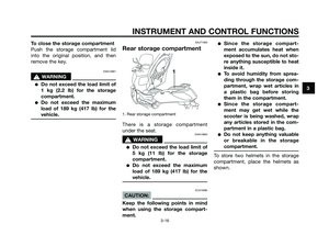
Rear storage compartment
1. Rear storage compartment
The rear storage compartment is
located under the seat. (See page
3-14.)
ECAT1030
CAUTION:
Keep the following points in mind
when using the rear storage com-
partment.
●Since the rear storage com-
partment accumulates heat
when exposed to the sun, do
not store anything susceptible
to heat inside it.
●To avoid humidity from sprea-
ding through the rear storagecompartment, wrap wet arti-
cles in a plastic bag before sto-
ring them in the compartment.
●Since the rear storage com-
partment may get wet while the
scooter is being washed, wrap
any articles stored in the rear
compartment in a plastic bag.
●Do not keep anything valuable
or breakable in the rear storage
compartment.
EWAT1050
s s
WARNING
●Do not exceed the load limit of
5 kg (11 lb) for the rear storage
compartment.
●Do not exceed the maximum
load of 189 kg (417 lb) for the
vehicle.
EAU14541
Front storage compartment
To open the storage compartment
1. Lock
Insert the key into the lock, turn it
clockwise, and then pull on it to open
the storage compartment lid.
1. Front storage compartment
INSTRUMENT AND CONTROL FUNCTIONS
3-15
3
1B9-F8199-E2.qxd 13/11/07 12:18 Página 30
Page 31 of 88
 for the sto")
To close the storage compartment
Push the storage compartment lid
into the original position, and then
remove the key.
EWA10961
s s
WARNING
●Do not exceed the load limit of
1 kg (2.2 lb) for the storage
compartment.
●Do not exceed the maximum
load of 189 kg (417 lb) for the
vehicle.
EAUT1060
Rear storage compartment
1. Rear storage compartment
There is a storage compartment
under the seat.
EWA10960
s s
WARNING
●Do not exceed the load limit of
5 kg (11 lb) for the storage
compartment.
●Do not exceed the maximum
load of 189 kg (417 lb) for the
vehicle.
ECA10080
CAUTION:
Keep the following points in mind
when using the storage compart-
ment.
●Since the storage compart-
ment accumulates heat when
exposed to the sun, do not sto-
re anything susceptible to heat
inside it.
●To avoid humidity from sprea-
ding through the storage com-
partment, wrap wet articles in
a plastic bag before storing
them in the compartment.
●Since the storage compart-
ment may get wet while the
scooter is being washed, wrap
any articles stored in the com-
partment in a plastic bag.
●Do not keep anything valuable
or breakable in the storage
compartment.
To store two helmets in the storage
compartment, place the helmets as
shown.
INSTRUMENT AND CONTROL FUNCTIONS
3
3-16
1B9-F8199-E2.qxd 13/11/07 12:18 Página 31
Page 32 of 88

NOTE:
●Some helmets cannot be stored
in the storage compartment
because of their size or shape.
●Do not leave your scooter unat-
tended with the seat open.
EAU14880
Adjusting the shock
absorber assemblies
Each shock absorber assembly is
equipped with a spring preload adjus-
ting ring.
ECA10100
CAUTION:
Never attempt to turn an adjusting
mechanism beyond the maximum
or minimum settings.
EWA10210
s s
WARNING
Always adjust both shock absorber
assemblies equally, otherwise poor
handling and loss of stability may
result.
Adjust the spring preload as follows.
To increase the spring preload and
thereby harden the suspension, turn
the adjusting ring on each shock
absorber assembly in direction (a). To
decrease the spring preload and the-
reby soften the suspension, turn the
adjusting ring on each shock absor-
ber assembly in direction (b).
1. Spring preload adjusting ring
2. Position indicator
NOTE:
Align the appropriate notch in the
adjusting ring with the position indica-
tor on the shock absorber.
Spring preload setting:
Minimum (soft):
1
Standard:
1
Maximum (hard):
4
INSTRUMENT AND CONTROL FUNCTIONS
3-17
3
1B9-F8199-E2.qxd 13/11/07 12:18 Página 32