2008 YAMAHA WR 250F transmission
[x] Cancel search: transmissionPage 156 of 224

5-60
CRANKCASE AND CRANKSHAFT
DISASSEMBLING THE
CRANKCASE
1. Separate:• Right crankcase
• Left crankcase
Separation steps:
a. Remove the crankcase bolts "1", hose guide "2" and clutch cable
holder "3".
Loosen each bolt 1/4 of a turn at a
time and after all the bolts are loos-
ened, remove them.
b. Remove the right crankcase "4".
• Place the crankcase with its left
side downward and split it by insert-
ing a screwdriver tip into the split-
ting slit "a" in the crankcase.
• Lift the right crankcase horizontally while lightly patting the case split-
ting slit and engine mounting boss
using a soft hammer, and leave the
crankshaft and transmission with
the left crankcase.
Use soft hammer to tap on the
case half. Tap only on reinforced
portions of case. Do not tap on
gasket mating surface. Work slow-
ly and carefully. Make sure the
case halves separate evenly. If the
cases do not separate, check for a
remaining case bolt or fitting. Do
not force.
c. Remove the dowel pins and O-
ring.
REMOVING THE CRANKSHAFT
1. Remove:• Crankshaft "1"
Use the crankcase separating
tool "2".
Do not use a hammer to drive out
the crankshaft.
REMOVING THE CRANKCASE
BEARING
1. Remove:•Bearing "1"
• Remove the bearing from the crankcase by pressing its inner
race.
• Do not use the removed bearing.
CHECKING THE TIMING CHAIN
AND TIMING CHAIN GUIDE
1. Inspect: • Timing chain
Cracks/stiff →Replace the timing
chain and camshaft sprocket as a
set.
2. Inspect: • Timing chain guideWear/damage →Replace. CHECKING THE CRANKCASE
1. Inspect:
• Contacting surface "a"Scratches →Replace.
• Engine mounting boss "b", crank- case
Cracks/damage →Replace.
2. Inspect: • BearingRotate inner race with a finger.
Rough spot/seizure →Replace.
3. Inspect: • Oil sealDamage →Replace.
CHECKING THE CRANKSHAFT
1. Measure: • Runout limit "a"
• Small end free play limit "b"
• Connecting rod big end side clearance "c"
• Crank width "d" Out of specification →Replace.
Use the dial gauge and a thick-
ness gauge.
Crankcase separating
tool: YU-1135-A/90890-
01135
Dial gauge and stand: YU-3097/90890-01252
Standard
Runo
ut lim-
it: 0.03 mm (0.0012
in) 0.05
mm
(0.002 in)
Small
end
free
play: 0.4–1.0 mm
(0.016–0.039 in) 2.0 mm
(0.08 in)
Side
clear-
ance: 0.15–0.45 mm
(0.0059–0.0177 in) 0.50
mm
(0.02 in)
Crack
width: 55.95–56.00
mm (2.203–
2.205 in) —
Page 157 of 224

5-61
CRANKCASE AND CRANKSHAFT
CHECKING THE OIL STRAINER
1. Inspect:• Oil strainer
Damage →Replace.
CHECKING THE OIL DELIVERY
PIPE 2
1. Inspect: • Oil delivery pipe 2 "1"
• O-ring "2"
Damage →Replace.
• Oil orifice "a" Clogged →Blow.
INSTALLING THE CRANKCASE
BEARING
1. Install: • Bearing
• Bearing stopper
• Bolt (bearing stopper)
• Screw (bearing stopper) • Screw [bearing stopper (crank-
shaft)] "1"
To left and right crankcase.
• Install the bearing by pressing its outer race parallel.
• To prevent the screw [bearing stop- per (crankshaft)] from becoming
loose, crush the screw head periph-
ery "a" into the concave "b" using a
punch etc. In so doing, take care
not to damage the screwdriver re-
ceiving hole in the screw head.
INSTALLING THE CRANKSHAFT
1. Install:
• Crankshaft "1"Use the crankshaft installing tool
"2", "3", "4" and "5".
• Hold the connecting rod at top dead center with one hand while turning
the nut of the installing tool with the
other. Operate the installing tool un-
til the crankshaft bottoms against
the bearing.
• Before installing the crankshaft, clean the contacting surface of
crankcase.
Do not use a hammer to drive in
the crankshaft.
A. For USA and CDN
B. Except for USA and CDN
2. Check:
• Shifter operation
• Transmission operationUnsmooth operation →Repair.
3. Install: • Oil strainer "1"
• Bolt (oil strainer) "2"
4. Apply: • Sealant
On the right crankcase "1".
Clean the contacting surface of left
and right crankcase before applying
the sealant.
Bolt (bearing stopper): 10 Nm (1.0 m•kg, 7.2
ft•lb)
Screw (bearing stopper): 10 Nm (1.0 m•kg, 7.2
ft•lb)
Screw [bearing stopper
(crankshaft)]:14 Nm (1.4 m•kg, 10
ft•lb)
Crankshaft installing pot
"2": YU-90050/90890-01274
Crankshaft installing bolt
"3": YU-90050/90890-01275
Adapter (M12) "4": YU-90063/90890-01278
Spacer (crankshaft in-
staller) "5": YU-91044/90890-04081
Bolt (oil strainer):
10 Nm (1.0 m•kg, 7.2
ft•lb)
YAMAHA Bond No. 1215
(ThreeBond
® No.1215):
90890-85505
Page 158 of 224

5-62
CRANKCASE AND CRANKSHAFT
5. Install:• Dowel pin "1"
• O-ring "2"
• Right crankcaseTo left crankcase.
• Apply the lithium soap base grease
on the O-ring.
• Fit the right crankcase onto the left crankcase. Tap lightly on the case
with soft hammer.
• When installing the crankcase, the connecting rod should be posi-
tioned at TDC (top dead center).
6. Tighten:
• Hose guide "1"
• Clutch cable holder "2"
• Bolt (crankcase) "3"
Tighten the crankcase tightening
bolts in stage, using a crisscross pat-
tern.
7. Install:• Oil delivery pipe 2 "1"
• O-ring "2"
• Bolt (oil delivery pipe 2) "3"
Apply the lithium soap base grease
on the Orings.
8. Install:• Timing chain "1"
• Timing chain guide (intake side)
"2"
• Bolt (timing chain guide) "3"
9. Remove: • Sealant
Forced out on the cylinder mating
surface.
10. Apply:
• Engine oilTo the crank pin, bearing and oil
delivery hole.
11. Check: • Crankshaft and transmission op-eration.
Unsmooth operation →Repair.
Bolt (crankcase):
12 Nm (1.2 m•kg, 8.7
ft•lb)
Bolt (oil delivery pipe 2): 10 Nm (1.0 m•kg, 7.2
ft•lb)
Bolt (timing chain guide):10 Nm (1.0 m•kg, 7.2
ft•lb)
Page 159 of 224

5-63
TRANSMISSION, SHIFT CAM AND SHIFT FORK
TRANSMISSION, SHIFT CAM AND SHIFT FORK
REMOVING THE TRANSMISSION, SHIFT CAM AND SHIFT FORKOrder Part name Q'ty Remarks Engine Refer to "ENGINE REMOVAL" section.
Separate the crankcase. Refer to "CRANKCASE AND CRANK-
SHAFT" section.
1 Main axle 1 Refer to removal section.
2 Drive axle 1 Refer to removal section.
3 Shift cam 1 Refer to removal section.
4 Shift fork 3 1 Refer to removal section.
5 Shift fork 2 1 Refer to removal section.
6 Shift fork 1 1 Refer to removal section.
7 Collar 1
Page 160 of 224
5-64
TRANSMISSION, SHIFT CAM AND SHIFT FORK
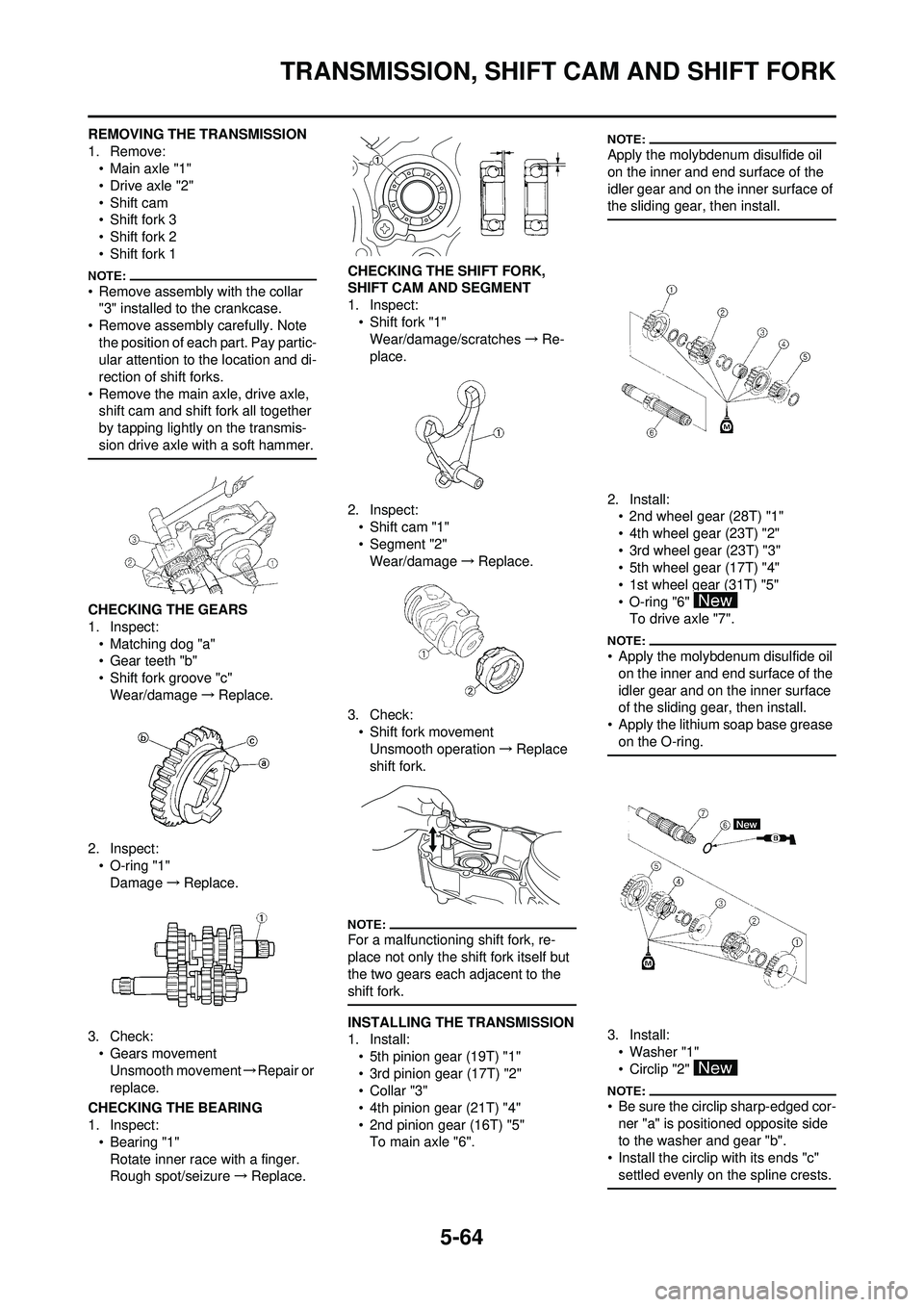
REMOVING THE TRANSMISSION
1. Remove:• Main axle "1"
• Drive axle "2"
• Shift cam
• Shift fork 3
• Shift fork 2
• Shift fork 1
• Remove assembly with the collar "3" installed to the crankcase.
• Remove assembly carefully. Note
the position of each part. Pay partic-
ular attention to the location and di-
rection of shift forks.
• Remove the main axle, drive axle, shift cam and shift fork all together
by tapping lightly on the transmis-
sion drive axle with a soft hammer.
CHECKING THE GEARS
1. Inspect:
• Matching dog "a"
• Gear teeth "b"
• Shift fork groove "c"Wear/damage →Replace.
2. Inspect: • O-ring "1"
Damage →Replace.
3. Check: • Gears movementUnsmooth movement →Repair or
replace.
CHECKING THE BEARING
1. Inspect: • Bearing "1"
Rotate inner race with a finger.
Rough spot/seizure →Replace. CHECKING THE SHIFT FORK,
SHIFT CAM AND SEGMENT
1. Inspect:
• Shift fork "1"Wear/damage/scratches →Re-
place.
2. Inspect: • Shift cam "1"
• Segment "2"Wear/damage →Replace.
3. Check: • Shift fork movement
Unsmooth operation →Replace
shift fork.
For a malfunctioning shift fork, re-
place not only the shift fork itself but
the two gears each adjacent to the
shift fork.
INSTALLING THE TRANSMISSION
1. Install:
• 5th pinion gear (19T) "1"
• 3rd pinion gear (17T) "2"
• Collar "3"
• 4th pinion gear (21T) "4"
• 2nd pinion gear (16T) "5"To main axle "6".
Apply the molybdenum disulfide oil
on the inner and end surface of the
idler gear and on the inner surface of
the sliding gear, then install.
2. Install:• 2nd wheel gear (28T) "1"
• 4th wheel gear (23T) "2"
• 3rd wheel gear (23T) "3"
• 5th wheel gear (17T) "4"
• 1st wheel gear (31T) "5"
• O-ring "6" To drive axle "7".
• Apply the molybdenum disulfide oil on the inner and end surface of the
idler gear and on the inner surface
of the sliding gear, then install.
• Apply the lithium soap base grease
on the O-ring.
3. Install:• Washer "1"
• Circlip "2"
• Be sure the circlip sharp-edged cor-ner "a" is positioned opposite side
to the washer and gear "b".
• Install the circlip with its ends "c" settled evenly on the spline crests.
Page 161 of 224
5-65
TRANSMISSION, SHIFT CAM AND SHIFT FORK
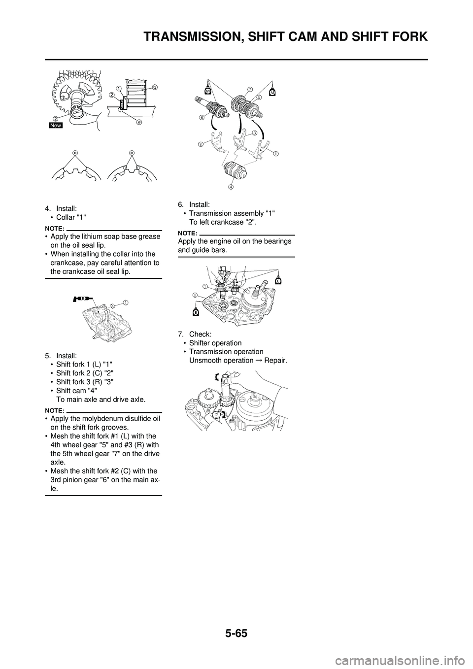
4. Install:•Collar "1"
• Apply the lithium soap base grease on the oil seal lip.
• When installing the collar into the crankcase, pay careful attention to
the crankcase oil seal lip.
5. Install:• Shift fork 1 (L) "1"
• Shift fork 2 (C) "2"
• Shift fork 3 (R) "3"
• Shift cam "4"
To main axle and drive axle.
• Apply the molybdenum disulfide oil on the shift fork grooves.
• Mesh the shift fork #1 (L) with the
4th wheel gear "5" and #3 (R) with
the 5th wheel gear "7" on the drive
axle.
• Mesh the shift fork #2 (C) with the 3rd pinion gear "6" on the main ax-
le.
6. Install:
• Transmission assembly "1"To left crankcase "2".
Apply the engine oil on the bearings
and guide bars.
7. Check:• Shifter operation
• Transmission operation
Unsmooth operation →Repair.
Page 206 of 224

7-5
ELECTRIC STARTING SYSTEM
4. Inspect:• Sealed portion of ignition coil "a"
• Spark plug terminal pin "b"
• Threaded portion of spark plug "c"Wear →Replace.
CHECKING THE AC MAGNETO
1. Inspect: • Pickup coil resistanceOut of specification →Replace. CHECKING THE NEUTRAL
SWITCH
1. Inspect:
• Neutral switch conduction
Not conductive while it is in neutral →
Replace.
Conductive while it is engaged →Re-
place.Set the tester selection position to " Ω
× 1".
CHECKING THE CDI UNIT
Check all electrical components. If no
fault is found, replace the CDI unit.
Then check the electrical compo-
nents again.
ELECTRIC STARTING
SYSTEM
STARTING CIRCUIT CUT-OFF
SYSTEM OPERATION
If the main switch is set to "ON", the
starter motor can only operate if at
least one of the following conditions is
met:
• The transmission is in neutral (the neutral switch is closed).
• The clutch lever is pulled to the han- dlebar (the clutch switch is closed).
The starting circuit cut-off relay pre-
vents the starter motor from operating
when neither of these conditions has
been met. In this instance, the start-
ing circuit cut-off relay is open so cur-
rent cannot reach the starter motor.
When at least one of the above con-
ditions has been met the starting cir-
cuit cut-off relay is closed and the
engine can be started by pressing the
start switch.
WHEN THE TRANSMISSION IS IN
NEUTRAL
WHEN THE CLUTCH LEVER IS
PULLED TO THE HANDLEBAR 1. Battery
2. Main fuse
3. Main switch
4. Starting circuit cut-off relay
5. Start switch
6. Diode
7. Clutch switch
8. Neutral switch
9. Starter relay
10. Starter motor
Secondary
coil resis- tance Tester se-
lector posi- tion
4.6–6.8
k Ωat 20 °C
(68 °F) k
Ω × 1
Tester (+) lead →Red lead "1"
Tester (-) lead →White lead "2"
Pickup coil resistance Tester se-
lector posi- tion
248–372 Ω
at 20 °C (68
°F) Ω × 100
Tester (+) lead
→Sky blue lead "1"
Tester (-) lead →Ground "2"
Result Conductive (while gear
is in neutral)