Page 8 of 158

EBU17420
TABLE OF CONTENTS
SAFETY INFORMATION .............................. 1-1
LOCATION OF THE WARNING AND
SPECIFICATION LABELS ............................ 2-1
DESCRIPTION .............................................. 3-1
Left view ...................................................... 3-1
Right view.................................................... 3-1
Controls and instruments ............................ 3-2
INSTRUMENT AND
CONTROL FUNCTIONS ................................ 4-1
Main switch ................................................ 4-1
Indicator lights and warning light ................ 4-2
Multifunction display ................................... 4-4
Handlebar switches .................................... 4-6
Throttle lever ............................................ 4-11
Speed limiter ............................................ 4-12
Front brake lever ...................................... 4-12
Brake pedal and rear brake lever ............. 4-13
Drive select lever ...................................... 4-14
Recoil starter ............................................ 4-14
Fuel tank cap ............................................ 4-14
Fuel .......................................................... 4-15Fuel cock ..................................................4-16
Starter (choke) ..........................................4-17
Seat ..........................................................4-18
Storage compartment ...............................4-19
Front carrier ..............................................4-20
Rear carrier ...............................................4-20
Adjusting the front and
rear shock absorber assemblies .............4-20
Auxiliary DC jack .......................................4-21
PRE-OPERATION CHECKS ..........................5-1
Pre-operation check list ..............................5-1
Fuel .............................................................5-3
Engine oil ....................................................5-3
Final gear oil ...............................................5-3
Differential gear oil ......................................5-3
Coolant .......................................................5-3
Front and rear brakes .................................5-4
Throttle lever ...............................................5-5
Tires ............................................................5-5
Measuring the tire pressure ........................5-6
Tire wear limit .............................................5-7
Chassis fasteners .......................................5-7
Instruments, lights and switches .................5-7U23D60E0.book Page 1 Thursday, March 15, 2007 7:59 PM
Page 14 of 158
1-4
1nition such as the pilot lights of water heat-
ers and clothes dryers. Gasoline can catch
fire and you could be burned.
�When transporting the ATV in another vehi-
cle, be sure it is kept upright and that the fuel
cock is in the “OFF” position. Otherwise, fuel
may leak out of the carburetor or fuel tank.�Gasoline is poisonous. If you should swal-
low some gasoline or inhale a lot of gasoline
vapor, or get some gasoline in your eyes,
seek medical help immediately. If gasoline
spills on your skin, wash with soap and wa-
ter. If gasoline spills on your clothing,change your clothes.
WARNING
EWB00070Always operate your ATV in an area with ade-
quate ventilation. Never start or run the engine
in a closed area. Exhaust fumes are poisonous
and may cause loss of consciousness anddeath within a short time.
U23D60E0.book Page 4 Thursday, March 15, 2007 7:59 PM
Page 24 of 158
4-1
4
EBU17731
INSTRUMENT AND CONTROL FUNCTIONS
EBU17760Main switch The positions of the main switch are as follows:
ON
All electrical systems are supplied with power. The
headlights and taillight come on when the light
switch is on, and the engine can be started. The
key cannot be removed.
OFF
All electrical systems are off. The key can be re-
moved.
1. Main switch
U23D60E0.book Page 1 Thursday, March 15, 2007 7:59 PM
Page 25 of 158

4-2
4
EBU17813Indicator lights and warning light EBU17842Reverse indicator light “”
This indicator light comes on when the transmis-
sion is in the reverse position.Furthermore, this indicator light flashes when the
engine is being raced for 10 seconds or more.
NOTE:If the indicator light flashes under any other circum-
stances or the speedometer does not show the
speed while riding, have a Yamaha dealer checkthe speed sensor circuit.EBU17860Neutral indicator light “”
This indicator light comes on when the transmis-
sion is in the neutral position.EBU17920Coolant temperature warning light “”
This warning light comes on when the engine over-
heats. When this occurs during operation, stop the
engine as soon as it is safe to do so and allow it to
cool down for about 10 minutes.CAUTION:ECB00010�The engine may overheat if the ATV is over-
loaded. In this case, reduce the load to spec-
ification.
1. On-Command differential gear lock indicator light “DIFF.
LOCK”
2. Low-range indicator light “L”
3. High-range indicator light “H”
4. Neutral indicator light “N”
5. Reverse indicator light “R”
6. Park indicator light “P”
7. On-Command four-wheel-drive/differential gear lock
indicator “”/“”
8. Coolant temperature warning light “”U23D60E0.book Page 2 Thursday, March 15, 2007 7:59 PM
Page 29 of 158

4-6
4
EBU18061Handlebar switches EBU18080Engine stop switch “/”
Set this switch to “” before starting the engine.
The engine stop switch controls the ignition and
stops the engine when it is running. Use this switch
to stop the engine in an emergency situation. The
engine will not start or run when this switch is set
to “”.
EBU18100Start switch “”
Push this switch to crank the engine with the start-
er.CAUTION:ECB00050See the starting instructions on page 6-1 priorto starting the engine.EBU18151Light switch “//OFF”
Set this switch to “” to turn on the low beams
and the taillight. Set the switch to “” to turn on
the high beams and the taillight. Set the switch to
“OFF” to turn off all the lights.CAUTION:ECB00040Do not use the headlights with the engine
turned off for an extended period of time, oth-
erwise the battery may discharge to the point
that the starter motor will not operate properly.
If this should happen, remove the battery andrecharge it.EBU18170Horn switch “”
Press the switch to sound the horn.
1. Light switch “//OFF”
2. Start switch “”
3. Engine stop switch “/”
4. Override switch “OVERRIDE”
5. Horn switch “”U23D60E0.book Page 6 Thursday, March 15, 2007 7:59 PM
Page 44 of 158
4-21
4
WARNING
EWB00400Always adjust the shock absorber assemblies
on the left and right side to the same setting.
Uneven adjustment can cause poor handling
and loss of stability, which could lead to an ac-cident.EBU19180Auxiliary DC jack The auxiliary DC jack is located at the front right
side of the ATV. The auxiliary DC jack can be used
for suitable work lights, radios, etc. The auxiliary
DC jack should only be used when the engine is
running.
1. Set the light switch to “OFF”.
2. Start the engine. (See page 6-1.)
3. Open the auxiliary DC jack cap, and then in-
sert the accessory power plug into the jack.
1. Special wrenchSpring preload setting:
Minimum (soft):
1
Standard:
2
Maximum (hard):
5
U23D60E0.book Page 21 Thursday, March 15, 2007 7:59 PM
Page 45 of 158
4-22
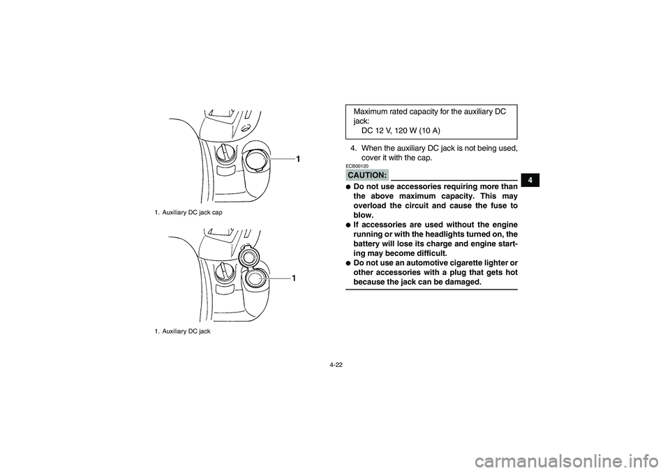
4 4. When the auxiliary DC jack is not being used,
cover it with the cap.
CAUTION:ECB00120�Do not use accessories requiring more than
the above maximum capacity. This may
overload the circuit and cause the fuse to
blow.�If accessories are used without the engine
running or with the headlights turned on, the
battery will lose its charge and engine start-
ing may become difficult.�Do not use an automotive cigarette lighter or
other accessories with a plug that gets hotbecause the jack can be damaged.
1. Auxiliary DC jack cap
1. Auxiliary DC jack
Maximum rated capacity for the auxiliary DC
jack:
DC 12 V, 120 W (10 A)
U23D60E0.book Page 22 Thursday, March 15, 2007 7:59 PM
Page 47 of 158

5-2
5
WARNING
EWB00480Always inspect your ATV each time you use it to make sure it is in safe operating condition.
Always follow the inspection and maintenance procedures and schedules described in the Owner’sManual. Failure to inspect increases the possibility of an accident or equipment damage.Rear brakeCheck operation. If soft or spongy, have Yamaha dealer bleed hy-
draulic system.
Check lever free play, and adjust if necessary.
Check brake pads for wear, and replace if necessary.
Check brake fluid level in reservoir, and add recommended brake
fluid to specified level if necessary.
Check hydraulic system for leakage. Correct if necessary.5-4, 8-38, 8-39, 8-42
Throttle leverMake sure that operation is smooth. Lubricate cable and lever hous-
ing if necessary.
Check cable free play, and adjust if necessary.5-5, 8-37
Control cablesMake sure that operation is smooth. Lubricate if necessary. 8-45
Wheels and tiresCheck wheel condition, and replace if damaged.
Check tire condition and tread depth. Replace if necessary.
Check air pressure. Correct if necessary.5-5, 5-6, 5-7
Brake pedal Make sure that operation is smooth. Lubricate pedal pivoting point if
necessary.8-46
Brake leversMake sure that operation is smooth. Lubricate lever pivoting points if
necessary.8-45
Axle bootsCheck for cracks or damage, and replace if necessary. 8-44
Chassis fastenersMake sure that all nuts, bolts and screws are properly tightened. 5-7
Instruments, lights and
switchesCheck operation, and correct if necessary. 5-7 ITEM ROUTINE PAGE
U23D60E0.book Page 2 Thursday, March 15, 2007 7:59 PM