Page 7 of 104

TABLE OF CONTENTS
Lubricating the swingarm pivots ... 6-25
Lubricating the rear suspension ... 6-25
Checking the front fork ................. 6-25
Checking the steering ................... 6-26
Checking the wheel bearings ....... 6-27
Battery .......................................... 6-27
Replacing the fuses ...................... 6-28
Headlight bulb .............................. 6-30
Front turn signal light .................... 6-30
Replacing a rear turn signal light
bulb or a tail/brake light bulb ..... 6-30
Replacing the license plate light
bulb ........................................... 6-31
Auxiliary light bulb ........................ 6-32
Troubleshooting ............................ 6-32
Troubleshooting charts ................. 6-33
MOTORCYCLE CARE AND
STORAGE.......................................... 7-1
Matte color caution ......................... 7-1
Care ................................................ 7-1
Storage ...........................................7-3
SPECIFICATIONS ............................. 8-1
CONSUMER INFORMATION............. 9-1
Identification numbers .................... 9-1
U2D2E2E0.book Page 2 Thursday, October 11, 2007 9:15 AM
Page 13 of 104
DESCRIPTION
2-2
2
EAU10420
Right view1. Storage compartment (page 3-25)
2. Fuel tank cap (page 3-20)
3. Fuse box (page 6-28)
4. Windshield (page 3-15)
5. Battery (page 6-27)
6. Main fuse (page 6-28)
7. Front fork compression damping force adjusting screw (page 3-29)
8. Brake pedal (page 3-18)9. Shock absorber assembly rebound damping force adjusting knob
(page 3-30)
10.Rear brake fluid reservoir (page 6-21)
U2D2E2E0.book Page 2 Thursday, October 11, 2007 9:15 AM
Page 18 of 104

INSTRUMENT AND CONTROL FUNCTIONS
3-4
3To unlock the steering
Push the key into the main switch, and
then turn it to “OFF” while still pushing
it.
WARNING
EWA10060
Never turn the key to “OFF” or
“LOCK” while the vehicle is moving,
otherwise the electrical systems will
be switched off, which may result in
loss of control or an accident. Make
sure that the vehicle is stopped be-
fore turning the key to “OFF” or“LOCK”.
EAU39460
(Parking)
The steering is locked, and the tail-
lights, license plate light and auxiliary
lights are on. The hazard lights and turn
signal lights can be turned on, but all
other electrical systems are off. The
key can be removed.
The steering must be locked before the
key can be turned to“”.
CAUTION:
ECA11020
Do not use the parking position for
an extended length of time, other-wise the battery may discharge.
EAU11003
Indicator and warning lights
EAU11030
Turn signal indicator lights“”
and“”
The corresponding indicator light flash-
es when the turn signal switch is
pushed to the left or right.
1. Push.
2. Turn.
1. Left turn signal indicator light“”
2. Right turn signal indicator light“”
3. Engine trouble“”/YCC-S“” indi-
cators and warning light
4. Anti-lock Brake System (ABS) warning
light“”
5. Neutral indicator light“”
6. High beam indicator light“”
7. Oil level warning light“”
8. Immobilizer system indicator light
SHIFT
ABS
U2D2E2E0.book Page 4 Thursday, October 11, 2007 9:15 AM
Page 40 of 104
INSTRUMENT AND CONTROL FUNCTIONS
3-26
3
�
Do not exceed the maximum
load of 208 kg (459 lb) for the ve-hicle.
EAU39480
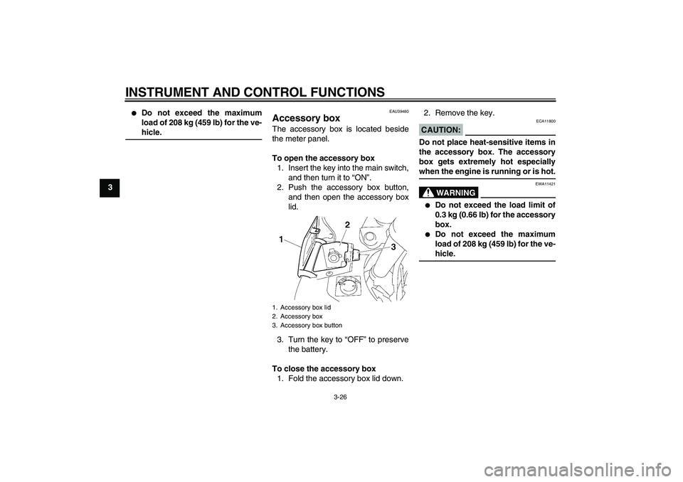
Accessory box The accessory box is located beside
the meter panel.
To open the accessory box
1. Insert the key into the main switch,
and then turn it to “ON”.
2. Push the accessory box button,
and then open the accessory box
lid.
3. Turn the key to “OFF” to preserve
the battery.
To close the accessory box
1. Fold the accessory box lid down.2. Remove the key.
CAUTION:
ECA11800
Do not place heat-sensitive items in
the accessory box. The accessory
box gets extremely hot especiallywhen the engine is running or is hot.
WARNING
EWA11421
�
Do not exceed the load limit of
0.3 kg (0.66 lb) for the accessory
box.
�
Do not exceed the maximum
load of 208 kg (459 lb) for the ve-hicle.
1. Accessory box lid
2. Accessory box
3. Accessory box button
U2D2E2E0.book Page 26 Thursday, October 11, 2007 9:15 AM
Page 49 of 104

INSTRUMENT AND CONTROL FUNCTIONS
3-35
3
EAU39651
Auxiliary DC jack This vehicle is equipped with an auxilia-
ry DC jack in the accessory box.
A 12-V accessory connected to the
auxiliary jack can be used when the key
is in the “ON” position and should only
be used when the engine is running.CAUTION:
ECA15430
The accessory connected to the
auxiliary DC jack should not be used
with the engine turned off, and the
load must never exceed 30 W (2.5 A),
otherwise the battery may dis-charge.
To use the auxiliary DC jack
1. Open the accessory box lid. (See
page 3-26.)
2. Turn the key to “OFF”.
3. Remove the auxiliary DC jack cap.4. Insert the accessory plug into the
auxiliary DC jack.
5. Turn the key to “ON”, and then
start the engine. (See page 5-1.)
WARNING
EWA14360
To prevent electrical shock or short-
circuiting, make sure that the cap is
installed when the auxiliary DC jackis not being used.
1. Auxiliary DC jack cap
1. Auxiliary DC jack
U2D2E2E0.book Page 35 Thursday, October 11, 2007 9:15 AM
Page 54 of 104

OPERATION AND IMPORTANT RIDING POINTS
5-2
5
CAUTION:
ECA15510
The following warning lights, indica-
tor light and indicators should come
on for a few seconds, then go off.�
Oil level warning light
�
Engine trouble/YCC-S indica-
tors and warning light
�
Immobilizer system indicator
light
�
ABS warning light
If a warning or indicator light, or an
indicator does not go off, see page
3-4 for the corresponding circuit
check.
2. Shift the transmission into the neu-
tral position with the front or rear
brake applied.NOTE:When the transmission is in the neutral
position, the neutral indicator light
should be on, otherwise have a
Yamaha dealer check the electrical cir-cuit.
3. Start the engine by pushing the
start switch.
NOTE:If the engine fails to start, release the
start switch, wait a few seconds, and
then try again. Each starting attempt
should be as short as possible to pre-
serve the battery. Do not crank the en-
gine more than 10 seconds on any oneattempt.CAUTION:
ECA11040
For maximum engine life, never ac-
celerate hard when the engine iscold!
EAU40572
Shifting Shifting gears lets you control the
amount of engine power available for
starting off, accelerating, climbing hills,
etc.1. Shift pedal
2. Neutral position
1. Hand shift lever
2. Neutral position
U2D2E2E0.book Page 2 Thursday, October 11, 2007 9:15 AM
Page 84 of 104

PERIODIC MAINTENANCE AND MINOR REPAIR
6-27
6
EAU23290
Checking the wheel bearings The front and rear wheel bearings must
be checked at the intervals specified in
the periodic maintenance and lubrica-
tion chart. If there is play in the wheel
hub or if the wheel does not turn
smoothly, have a Yamaha dealer check
the wheel bearings.
EAU39521
Battery The battery is located under panel A.
(See page 6-7.)
This vehicle is equipped with a sealed-
type (MF) battery, which does not re-
quire any maintenance. There is no
need to check the electrolyte or to add
distilled water.
To charge the battery
Have a Yamaha dealer charge the bat-
tery as soon as possible if it seems to
have discharged. Keep in mind that thebattery tends to discharge more quickly
if the vehicle is equipped with optional
electrical accessories.
WARNING
EWA10760
�
Electrolyte is poisonous and
dangerous since it contains sul-
furic acid, which causes severe
burns. Avoid any contact with
skin, eyes or clothing and al-
ways shield your eyes when
working near batteries. In case
of contact, administer the fol-
lowing FIRST AID.
EXTERNAL: Flush with plenty
of water.
INTERNAL: Drink large quan-
tities of water or milk and im-
mediately call a physician.
EYES: Flush with water for 15
minutes and seek prompt
medical attention.
�
Batteries produce explosive hy-
drogen gas. Therefore, keep
sparks, flames, cigarettes, etc.,
away from the battery and pro-
vide sufficient ventilation when
charging it in an enclosed
space.
1. Battery
2. Positive battery lead (red)
3. Negative battery lead (black)
U2D2E2E0.book Page 27 Thursday, October 11, 2007 9:15 AM
Page 85 of 104

PERIODIC MAINTENANCE AND MINOR REPAIR
6-28
6
�
KEEP THIS AND ALL BATTER-
IES OUT OF THE REACH OFCHILDREN.
To store the battery
1. If the vehicle will not be used for
more than one month, remove the
battery, fully charge it, and then
place it in a cool, dry place.
2. If the battery will be stored for more
than two months, check it at least
once a month and fully charge it if
necessary.
3. Fully charge the battery before in-
stallation.
4. After installation, make sure that
the battery leads are properly con-
nected to the battery terminals.
CAUTION:
ECA10630
�
Always keep the battery
charged. Storing a discharged
battery can cause permanent
battery damage.
�
To charge a sealed-type (MF)
battery, a special (constant-volt-
age) battery charger is required.
Using a conventional batterycharger will damage the battery.
If you do not have access to a
sealed-type (MF) battery charg-
er, have a Yamaha dealer
charge your battery.
EAU23658
Replacing the fuses The main fuse, the fuse boxes and the
ABS motor fuse are located under pan-
el A. (See page 6-7.)1. Main fuse
2. Fuse box
3. ABS motor fuse
4. ABS motor spare fuse
U2D2E2E0.book Page 28 Thursday, October 11, 2007 9:15 AM

2. Fuel tank cap (page 3-20)
3. Fuse box (page 6-28)
4. Windshield (page 3-15)
5. Battery (page 6-27)
6. Main fuse (page 6-28)
7")