Page 33 of 104
 features a dual electronic con-
trol system, which acts on the front and
rear brakes independently. The ABS")
INSTRUMENT AND CONTROL FUNCTIONS
3-19
3
EAU39531
ABS The Yamaha ABS (Anti-lock Brake
System) features a dual electronic con-
trol system, which acts on the front and
rear brakes independently. The ABS is
monitored by an ECU (Electronic Con-
trol Unit), which will have recourse to
manual braking if a malfunction occurs.
WARNING
EWA10090
�
The ABS performs best on long
braking distances.
�
On certain (rough or gravel)
roads, the braking distance may
be longer with than without the
ABS. Therefore, always keep a
sufficient distance to the vehicle
ahead to match the ridingspeed.
NOTE:�
The ABS performs a self-diagno-
sis test for a few seconds each
time the vehicle first starts off after
the main switch was turned on.
During this test, a “clicking” noise
can be heard from under the seat,
and if the brake lever or brake ped-al are even slightly applied, a vi-
bration can be felt at the lever and
pedal, but these do not indicate a
malfunction.
�
When the ABS is activated, the
brakes are operated in the usual
way. A pulsating action may be felt
at the brake lever or brake pedal,
but this does not indicate a mal-
function.
�
This ABS has a test mode which
allows the owner to experience the
pulsating at the brake lever or
brake pedal when the ABS is oper-
ating. However, special tools are
required, so please consult your
Yamaha dealer when performingthis test.
CAUTION:
ECA16120
Keep any type of magnets (including
magnetic pick-up tools, magnetic
screwdrivers, etc.) away from the
front and rear wheel hubs, otherwise
the magnetic rotors equipped in the
wheel hubs may be damaged, result-
ing in improper performance of theABS system.
1. Front wheel hub
1. Rear wheel hub
11
U2D2E2E0.book Page 19 Thursday, October 11, 2007 9:15 AM
Page 34 of 104

INSTRUMENT AND CONTROL FUNCTIONS
3-20
3
EAU13072
Fuel tank cap To open the fuel tank cap
Open the fuel tank cap lock cover, in-
sert the key into the lock, and then turn
it 1/4 turn clockwise. The lock will be re-
leased and the fuel tank cap can be
opened.
To close the fuel tank cap
1. Push the fuel tank cap into position
with the key inserted in the lock.
2. Turn the key counterclockwise to
the original position, remove it, and
then close the lock cover.
NOTE:The fuel tank cap cannot be closed un-
less the key is in the lock. In addition,
the key cannot be removed if the cap isnot properly closed and locked.
WARNING
EWA11090
Make sure that the fuel tank cap isproperly closed before riding.
EAU13220
Fuel Make sure that there is sufficient fuel in
the tank. When refueling, be sure to in-
sert the pump nozzle into the fuel tank
filler hole and to fill the tank to the bot-
tom of the filler tube as shown.
WARNING
EWA10880
�
Do not overfill the fuel tank, oth-
erwise it may overflow when the
fuel warms up and expands.
�
Avoid spilling fuel on the hot en-gine.
1. Fuel tank cap lock cover
2. Unlock.
1. Fuel tank filler tube
2. Fuel level
U2D2E2E0.book Page 20 Thursday, October 11, 2007 9:15 AM
Page 36 of 104

INSTRUMENT AND CONTROL FUNCTIONS
3-22
3
EAU13442
Catalytic converters This vehicle is equipped with catalytic
converters in the exhaust system.
WARNING
EWA10860
The exhaust system is hot after op-
eration. Make sure that the exhaust
system has cooled down before do-ing any maintenance work.CAUTION:
ECA10700
The following precautions must be
observed to prevent a fire hazard or
other damages.�
Use only unleaded gasoline.
The use of leaded gasoline will
cause unrepairable damage to
the catalytic converter.
�
Never park the vehicle near pos-
sible fire hazards such as grass
or other materials that easily
burn.
�
Do not allow the engine to idletoo long.
EAU39492
Seats Passenger seat
To remove the passenger seat1. Insert the key into the passenger
seat lock, and then turn it counter-
clockwise.
2. Lift the front of the passenger seat
and pull it forward.To install the passenger seat
1. Insert the projections on the rear of
the passenger seat into the seat
holders as shown, and then push
the front of the seat down to lock it
in place.
2. Remove the key.
Rider seat
To remove the rider seat1. Remove the passenger seat.
2. Push the rider seat lock lever, lo-
cated under the back of the rider
seat, to the left as shown, and then
pull the seat off.
1. Passenger seat lock
2. Unlock.
1. Projection
2. Seat holder
U2D2E2E0.book Page 22 Thursday, October 11, 2007 9:15 AM
Page 39 of 104

INSTRUMENT AND CONTROL FUNCTIONS
3-25
3
5. Insert the projection on the front of
the rider seat into seat holder A as
shown.6. Align the projection on the bottom
of the rider seat with the “L” posi-
tion slot, and then push the rear of
the seat down to lock it in place as
shown.
7. Install the passenger seat.
NOTE:
Make sure that the seats are properlysecured before riding.
EAU14422
Storage compartment This storage compartment is designed
to hold a genuine Yamaha
CYCLELOK. (Other locks may not fit.)
When placing a CYCLELOK in the stor-
age compartment, securely fasten it
with the straps. When the CYCLELOK
is not in the storage compartment, be
sure to secure the straps to prevent los-
ing them.
WARNING
EWA10961
�
Do not exceed the load limit of 3
kg (7 lb) for the storage com-
partment.
1. Rider seat height position adjuster
2.“L” mark
3. Match mark
1. Projection
2. Seat holder A (for low position)
3. Rider seat holder cover
1.“L” position slot
1. Storage compartment
2. Yamaha CYCLELOK (optional)
U2D2E2E0.book Page 25 Thursday, October 11, 2007 9:15 AM
Page 40 of 104
INSTRUMENT AND CONTROL FUNCTIONS
3-26
3
�
Do not exceed the maximum
load of 208 kg (459 lb) for the ve-hicle.
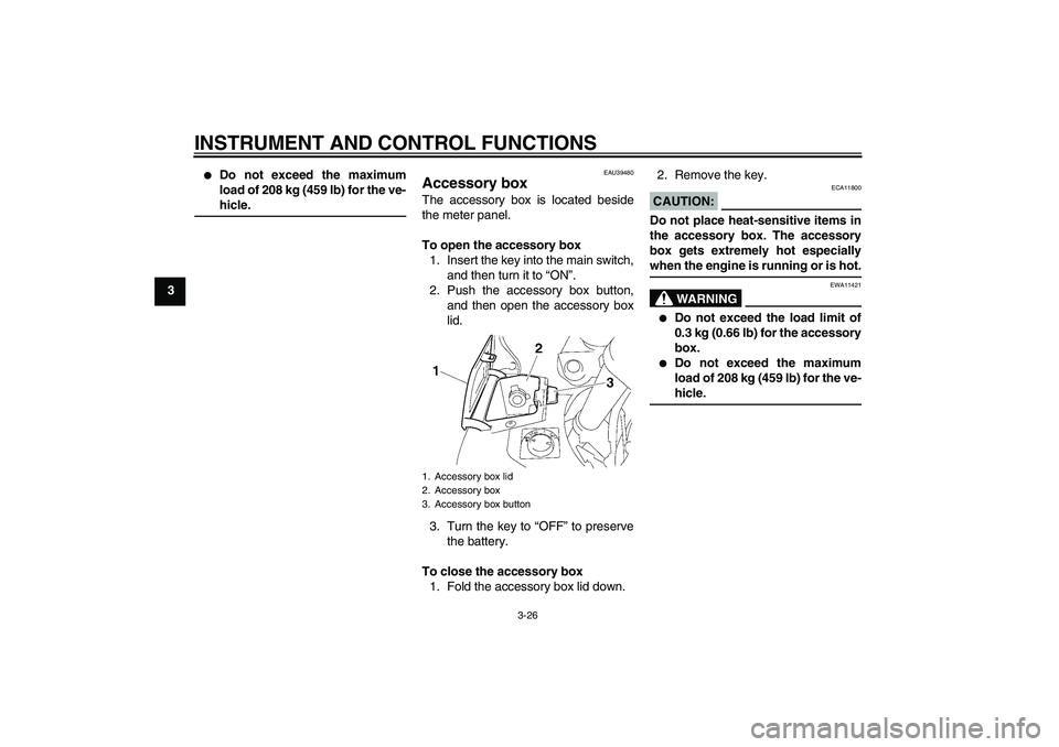
EAU39480
Accessory box The accessory box is located beside
the meter panel.
To open the accessory box
1. Insert the key into the main switch,
and then turn it to “ON”.
2. Push the accessory box button,
and then open the accessory box
lid.
3. Turn the key to “OFF” to preserve
the battery.
To close the accessory box
1. Fold the accessory box lid down.2. Remove the key.
CAUTION:
ECA11800
Do not place heat-sensitive items in
the accessory box. The accessory
box gets extremely hot especiallywhen the engine is running or is hot.
WARNING
EWA11421
�
Do not exceed the load limit of
0.3 kg (0.66 lb) for the accessory
box.
�
Do not exceed the maximum
load of 208 kg (459 lb) for the ve-hicle.
1. Accessory box lid
2. Accessory box
3. Accessory box button
U2D2E2E0.book Page 26 Thursday, October 11, 2007 9:15 AM
Page 42 of 104
INSTRUMENT AND CONTROL FUNCTIONS
3-28
3
2. Pull the cowling to the open posi-
tion, and then install the quick fas-
tener screws.
To close a cowling
1. Remove the quick fastener
screws.2. Push the cowling to the closed po-
sition, and then install the quick
fastener screws.
NOTE:Make sure that the cowling is properlyinstalled before riding.
EAU39671
Rear view mirrors The rear view mirrors of this vehicle can
be folded forward or backward for park-
ing in narrow spaces. Fold the mirrors
back to their original position before
riding.
WARNING
EWA14371
Be sure to fold the rear view mirrors
back to their original position beforeriding.
1. Quick fastener screw
1. Open position
1. Quick fastener screw
1. Closed position
1. Riding position
2. Parking position
U2D2E2E0.book Page 28 Thursday, October 11, 2007 9:15 AM
Page 43 of 104

INSTRUMENT AND CONTROL FUNCTIONS
3-29
3
EAU14731
Adjusting the front fork This front fork is equipped with spring
preload adjusting bolts, rebound damp-
ing force adjusting knobs and compres-
sion damping force adjusting screws.
WARNING
EWA10180
Always adjust both fork legs equal-
ly, otherwise poor handling and lossof stability may result.
Spring preload
To increase the spring preload and
thereby harden the suspension, turn
the adjusting bolt on each fork leg in di-
rection (a). To decrease the spring pre-load and thereby soften the
suspension, turn the adjusting bolt on
each fork leg in direction (b).
NOTE:Align the appropriate groove on the ad-
justing mechanism with the top of thefront fork cap bolt.Rebound damping force
To increase the rebound damping force
and thereby harden the rebound damp-
ing, turn the adjusting knob on each
fork leg in direction (a). To decrease the
rebound damping force and thereby
soften the rebound damping, turn the
adjusting knob on each fork leg in direc-
tion (b).
1. Spring preload adjusting bolt
1. Current setting
2. Front fork cap bolt
Spring preload setting:
Minimum (soft):
6
Standard:
4
Maximum (hard):
1
1. Rebound damping force adjusting knob
Rebound damping setting:
Minimum (soft):
17 click(s) in direction (b)*
Standard:
12 click(s) in direction (b)*
Maximum (hard):
1 click(s) in direction (b)*
* With the adjusting knob fully turned
in direction (a)
U2D2E2E0.book Page 29 Thursday, October 11, 2007 9:15 AM
Page 45 of 104
. For
riding with a passenger, move the
spring preload adjusting lever in direc-
tion (")
INSTRUMENT AND CONTROL FUNCTIONS
3-31
3 For riding solo, move the spring preload
adjusting lever in direction (b). For
riding with a passenger, move the
spring preload adjusting lever in direc-
tion (a).
Rebound damping force
To increase the rebound damping force
and thereby harden the rebound damp-
ing, turn the adjusting knob in direction
(a). To decrease the rebound damping
force and thereby soften the rebound
damping, turn the adjusting knob in di-
rection (b).
WARNING
EWA10220
This shock absorber contains highly
pressurized nitrogen gas. For prop-
er handling, read and understand
the following information before
handling the shock absorber. The
manufacturer cannot be held re-
sponsible for property damage or
personal injury that may result from
improper handling.�
Do not tamper with or attempt to
open the gas cylinder.
�
Do not subject the shock ab-
sorber to an open flame or other
high heat sources, otherwise it
may explode due to excessive
gas pressure.
�
Do not deform or damage the
gas cylinder in any way, as this
will result in poor damping per-
formance.
�
Always have a Yamaha dealerservice the shock absorber.
1. Rebound damping force adjusting knob
Rebound damping setting:
Minimum (soft):
20 click(s) in direction (b)*
Standard:
12 click(s) in direction (b)*
Maximum (hard):
3 click(s) in direction (b)*
* With the adjusting knob fully turned
in direction (a)
U2D2E2E0.book Page 31 Thursday, October 11, 2007 9:15 AM