2008 VOLVO S80 steering
[x] Cancel search: steeringPage 206 of 275
marks. For capacities and recommended fluid grade, see page 275.
WARNING
If a problem should occur in the power steering system or if the vehicle has no electrical current and must be towed,
it is still possible to steer the vehicle. However, keep in mind that greater effort will be required to turn the steering
wheel.
CAUTION
Keep the area around the power steering fluid reservoir clean when checking.
216 06 Maintenance and specifications
Replacing bulbs
Introduction
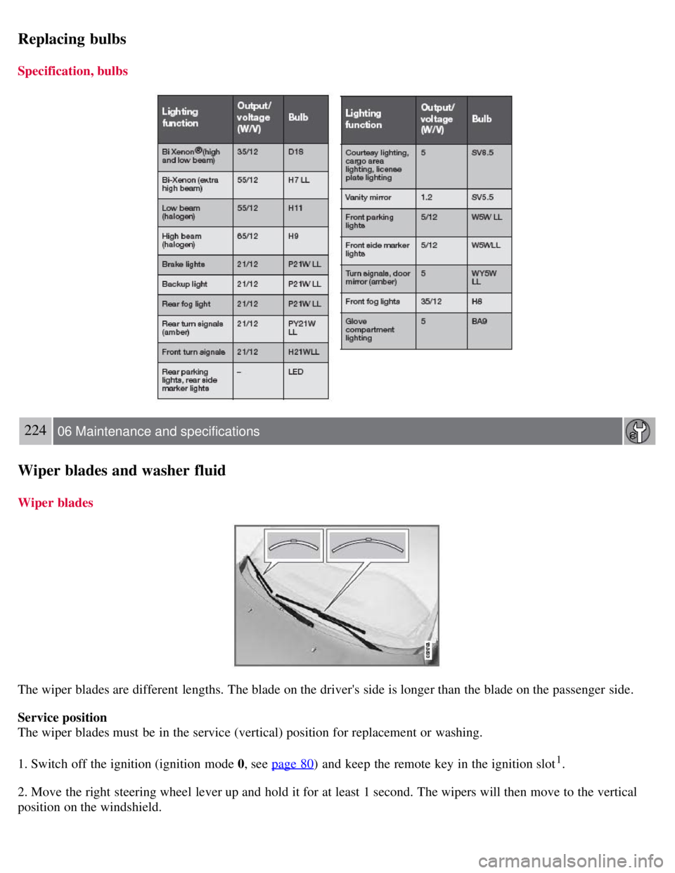
All bulb specifications are listed on page 223
. The following bulbs should only be replaced by a trained and qualified
Volvo service technician:
Dome lighting
Reading lights
Glove compartment lighting
Turn signals in the door mirror
Approach lighting in the door mirror
Brake lights
Active Bi -Xenon® and LED bulbs
WARNING
Active Bi -Xenon® headlights (option) - due to the high voltage used by these headlights, these bulbs should only
be replaced by a trained and qualified Volvo service technician.
Turn off the lights and remove the remote key from the ignition before changing any bulbs.
Headlight housing
Page 216 of 275
Replacing bulbs
Specification, bulbs
224 06 Maintenance and specifications
Wiper blades and washer fluid
Wiper blades
The wiper blades are different lengths. The blade on the driver's side is longer than the blade on the passenger side.
Service position
The wiper blades must be in the service (vertical) position for replacement or washing.
1. Switch off the ignition (ignition mode 0, see page 80
) and keep the remote key in the ignition slot1.
2. Move the right steering wheel lever up and hold it for at least 1 second. The wipers will then move to the vertical
position on the windshield.
Page 236 of 275
Self supporting run flat tires
Certain models equipped with the Tire Pressure Monitoring System (TPMS) can also be equipped with self supporting
run flat tires.
Tires of this type have specially reinforced sidewalls that make it possible to continue driving in the event of a drop in
inflation pressure. Tires of this type are mounted on special rims.
NOTE
Self supporting run flat tires are only available in conjunction with TPMS.
If a self supporting run flat tire should lose inflation pressure, the yellow TPMS warning symbol (
) in the
instrument panel lights up to alert the driver, and a message will be shown in the text window in the instrument panel.
If this occurs, reduce vehicle speed to a maximum of 50 mph (80 km/h). The vehicle can be driven approximately 50
miles (80 km), or somewhat farther if the vehicle is not heavily loaded. The tire should be replaced as soon as
possible.
Hard braking and sudden steering maneuvers should be avoided.
In certain cases, it may be difficult to see which self supporting run flat tire is defective. To determine which tire is
damaged, check the inflation pressure of all four tires.
WARNING
Only specially trained persons should mount self supporting run flat tires.
If self supporting run flat tires are mounted, the vehicle must be equipped with a Tire Pressure Monitoring
System.
After a low pressure warning has been displayed, do not exceed 50 mph (80 km/h).
Avoid severe cornering and hard braking, and minimize the distance traveled before replacing the self supporting
run flat tire.
Self supporting run flat tires cannot be repaired. They must be replaced if damaged or punctured.
245 06 Maintenance and specifications
Wheels and tires
Tire designations
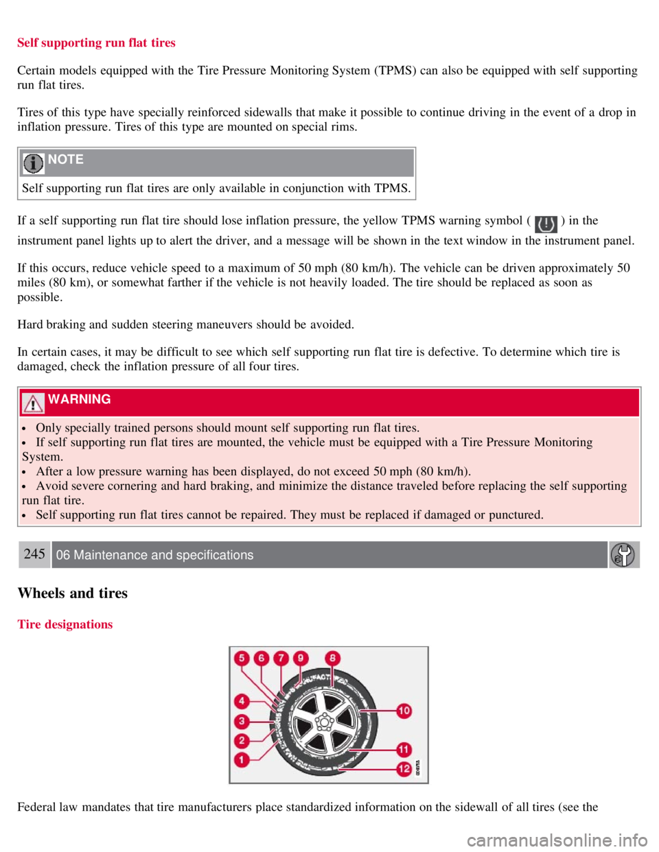
Federal law mandates that tire manufacturers place standardized information on the sidewall of all tires (see the
Page 242 of 275
WARNING
Current legislation prohibits the use of the "Temporary Spare" tire other than as a temporary replacement for a
punctured tire. It must be replaced as soon as possible by a standard tire. Road holding and handling may be affected
with the "Temporary Spare" in use. Do not exceed 50 mph (80 km/h).
CAUTION
The vehicle must not be driven with wheels of different dimensions or with a spare tire other than the one that came
with the vehicle. The use of different size wheels can seriously damage your car's transmission.
252 06 Maintenance and specifications
Wheels and tires
Summer and winter tires
When switching between summer and winter tires, mark the tires to indicate where they were mounted on the
vehicle, e.g. LF = left front, RR = right rear.
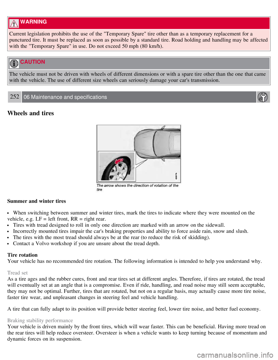
Tires with tread designed to roll in only one direction are marked with an arrow on the sidewall.
Incorrectly mounted tires impair the car's braking properties and ability to force aside rain, snow and slush.
The tires with the most tread should always be at the rear (to reduce the risk of skidding).
Contact a Volvo workshop if you are unsure about the tread depth.
Tire rotation
Your vehicle has no recommended tire rotation. The following information is intended to help you understand why.
Tread set
As a tire ages and the rubber cures, front and rear tires set at different angles. Therefore, if tires are rotated, the tread
will eventually set at an angle that is a compromise. Even if ride, handling, and road noise may still seem acceptable,
they may not be optimal. Further, tires that are rotated, but not on a regular basis, may actually cause more tire noise,
faster tire wear, and unpleasant changes in steering feel and vehicle handling.
A tire that can fully adapt to its position will provide better steering feel, lower tire noise, and better fuel economy.
Braking stability performance
Your vehicle is driven mainly by the front tires, which will wear faster. This can be beneficial. Having more tread on
the rear tires will help reduce oversteer. Oversteer is when a vehicle wants to keep turning because of momentum and
dynamic forces on its suspension.
Page 246 of 275
Tire sealing system
Certain models are equipped with a tire sealing system that enables you to temporarily seal a hole in the tread surface
and reinflate a flat tire, or to adjust a tire's inflation pressure.
The system consists of an air compressor, a container for the sealing compound, wiring to connect the system to the
vehicle's electrical system via one of the 12-volt sockets, and a hose used to connect the system to the tire's inflation
valve.
The 12-volt sockets are located in the front tunnel console, on the rear side of the center console in the rear seat. See
page 185
.
Accessing the tire sealing system
The tire sealing system is stowed under the floor of the trunk. To access it:
1. Fold up the floor carpeting, starting at the rear and working forward.
2. Remove the retaining screws
3. Lift out the foam plastic block holding the jack and lug wrench.
4. Lift out the tire sealing system.
NOTE
The tire sealing system is only intended to seal holes on the tire's tread area, not the sidewall.
Tires with large holes or tears cannot be repaired with the tire sealing system.
WARNING
After using the tire sealing system, the vehicle should not be driven farther than approximately 120 miles (200
km).
Have the tire inspected by a qualified service technician as soon as possible to determine if it can be permanently
repaired or must be replaced.
The vehicle should not be driven faster than 50 mph (80 km/h) while using a tire that has been temporarily
repaired with the tire sealing system.
After using the tire sealing system, drive carefully and avoid abrupt steering maneuvers and sudden stops.
257 06 Maintenance and specifications
Wheels and tires
Tire sealing system -overview
Page 249 of 275
259 06 Maintenance and specifications
Wheels and tires
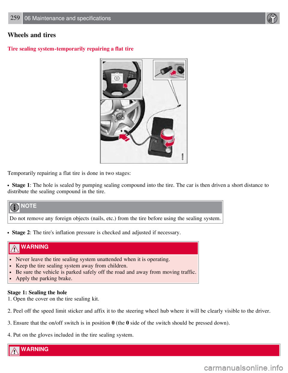
Tire sealing system-temporarily repairing a flat tire
Temporarily repairing a flat tire is done in two stages:
Stage 1: The hole is sealed by pumping sealing compound into the tire. The car is then driven a short distance to
distribute the sealing compound in the tire.
NOTE
Do not remove any foreign objects (nails, etc.) from the tire before using the sealing system.
Stage 2: The tire's inflation pressure is checked and adjusted if necessary.
WARNING
Never leave the tire sealing system unattended when it is operating.
Keep the tire sealing system away from children.
Be sure the vehicle is parked safely off the road and away from moving traffic.
Apply the parking brake.
Stage 1: Sealing the hole
1. Open the cover on the tire sealing kit.
2. Peel off the speed limit sticker and affix it to the steering wheel hub where it will be clearly visible to the driver.
3. Ensure that the on/off switch is in position 0 (the 0 side of the switch should be pressed down).
4. Put on the gloves included in the tire sealing system.
WARNING
Page 251 of 275
CAUTION
The compressor should not be used for more than 10 minutes at a time to avoid overheating.
WARNING
If the pressure remains below 22 psi (1.8 bar) after approximately seven minutes, turn off the compressor. In this
case, the hole is too large to be sealed and the vehicle should not be driven.
12. Switch off the compressor and disconnect the electrical wire from the 12-volt socket.
13. Unscrew the hose from the tire's inflation valve and reinstall the valve cap.
14. Immediately drive the vehicle for approximately 2 miles (3 km) at a maximum speed of 50 mph (80 km/h) to
distribute the sealing compound in the tire.
NOTE
Safely stow the tire sealing system in a convenient place as it will soon be used again to check the tire's inflation
pressure.
The empty bottle of sealing compound cannot be removed from the bottle holder. Consult a trained and qualified
Volvo service technician to have the bottle removed and properly disposed of.
WARNING
If heavy vibrations, unsteady steering behavior, or noises should occur while driving, reduce speed and park the
vehicle in a safe place. Recheck the tire for bumps, cracks, or other visible damage, and recheck its inflation
pressure. If the pressure is below 19 psi (1.3 bar), do not continue driving. Have the vehicle towed to a trained and
qualified Volvo service technician.
261 06 Maintenance and specifications
Wheels and tires
Stage 2: Checking inflation pressure
1. Connect the tire sealing system as described in stage 1.
2. Refer to the tables on pages 240 and 241
for the correct tire inflation pressure. If the tire needs to be inflated, start
the tire sealing system's compressor. If necessary, release air from the tire by turning the air release knob
counterclockwise.
CAUTION
The compressor should not be used for more than 10 minutes at a time to avoid overheating.
WARNING
If you interrupt your trip for more than 1 hour, check the inflation pressure in the damaged tire again before
continuing.
Page 264 of 275
2 0 0 8
VOLVO S80
278 Index
12-volt sockets 185
A
Accessory installation warning7
Active Bi -Xenon® headlights90
Active chassis system153
Active yaw control151
Adaptive cruise control156-159
Air conditioning130
Air distribution127
Air distribution table133
Air vents128
Airbags
disconnecting the front passenger's side 22-24
front19- 21
inflatable curtain27
side impact25
Alarm system 67-69
All Wheel Drive112
Anti-freeze190, 214
Anti-lock brake system113
warning light75
Approach lighting 54, 94
Audio system
audio functions 137
CD player/changer138, 138
menu control135
overview134
radio functions141
Sirius satellite radio143- 146
sound settings137
steering wheel keypad134
Auto-dim rearview mirror 100
Automatic locking63
Automatic locking retractor33
Automatic transmission