2008 VOLVO S80 run flat
[x] Cancel search: run flatPage 183 of 275

At highway driving speeds, fuel consumption will be lower with the air conditioning on and the windows closed
than with the air conditioning off and the windows open.
Using the onboard trip computer's fuel consumption modes can help you learn how to drive more economically.
Other factors that decrease gas mileage are:
Dirty air cleaner
Dirty engine oil and clogged oil filter
Dragging brakes
Incorrect front end alignment
Some of the above mentioned items and others are checked at the standard maintenance intervals.
WARNING
Driving with the trunk open : Driving with the trunk open could lead to poisonous exhaust gases entering the
passenger compartment. If the trunk must be kept open for any reason, proceed as follows:
Close the windows
Set the ventilation system control to air flow to floor, windshield and side windows and the blower control to its
highest setting.
Weight distribution affects handling
At the specified curb weight your vehicle has a tendency to understeer, which means that the steering wheel has to be
turned more than might seem appropriate for the curvature of a bend. This ensures good stability and reduces the risk
of rear wheel skid. Remember that these properties can alter with the vehicle load. The heavier the load in the cargo
area, the less the tendency to understeer.
Handling, roadholding
Vehicle load, tire design and inflation pressure all affect vehicle handling. Therefore, check that the tires are inflated to
the recommended pressure according to the vehicle load. See the "Tire pressure" section. Loads should be distributed
so that capacity weight
189 05 During your trip
Driving recommendations
or maximum permissible axle loads are not exceeded.
Driving through water
The vehicle can be driven through water up to a depth of approximately 9 in. (25 cm), at a maximum speed of 6 mph
(10 km/h).
Take particular care when driving through flowing water.
Clean the electrical connections for trailer wiring after driving in mud or water.
When driving through water, maintain low speed and do not stop in the water.
WARNING
After driving through water, press lightly on the brake pedal to ensure that the brakes are functioning normally.
Water or mud can make the brake linings slippery, resulting in delayed braking effect.
Page 191 of 275
To increase loading space, the rear seat backrests can be folded down, see page 85.
The trunk lid can be unlocked via the button located on the lighting panel, see page 64.
Load the cargo in the trunk against the backrest.
Load wide cargo in the trunk on both sides of the rear seat split.
Unstable loads can be secured to the load anchoring eyelets with straps or web lashings to help keep them from
shifting.
Folding down the rear seat backrests
See page 85
for information.
WARNING
The vehicle's driving characteristics may change depending on the weight and distribution of the load.
A 44-pound (20 kg) object produces a force of 2,200 pounds (1,000 kg) in a head-on collision at 30 mph (50
km/h).
Loading the cargo area
Stop the engine and apply the parking brake when loading or unloading long objects. The gear selector can be knocked
out of position by long loads, which could set the vehicle in motion. To increase loading space, the rear seat backrests
can be folded down, see page 85
.
WARNING
Stop the engine, put the gear selector in P , and apply the parking brake when loading or unloading long objects.
The rear seat should not be loaded to a level higher than 2 in. (5 cm) below the upper edge of the rear side
windows. Objects placed higher than this level could impede the function of the Volvo Inflatable Curtain.
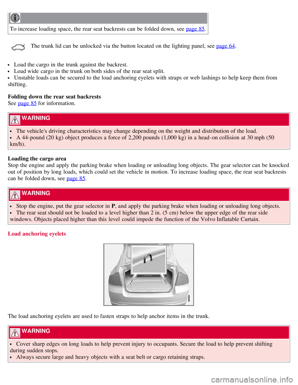
Load anchoring eyelets
The load anchoring eyelets are used to fasten straps to help anchor items in the trunk.
WARNING
Cover sharp edges on long loads to help prevent injury to occupants. Secure the load to help prevent shifting
during sudden stops.
Always secure large and heavy objects with a seat belt or cargo retaining straps.
Page 229 of 275
The tires have wear indicator strips running across or parallel to the tread. The letters TWI are printed on the side of
the tire. When approximately 1/16" (1.6 mm) is left on the tread, these strips become visible and indicate that the tire
should be replaced. Tires with less than 1/16" (1.6 mm) tread offer very poor traction.
When replacing worn tires, it is recommended that the tire be identical in type (radial) and size as the one being
replaced. Using a tire of the same make (manufacturer) will prevent alteration of the driving characteristics of the
vehicle.
WARNING
The wheel and tire sizes for your Volvo are specified to meet stringent stability and handling requirements.
Unapproved wheel/tire size combinations can negatively affect your vehicle's stability and handling. Approved tire
sizes are shown in the Tire inflation pressure tables beginning on page 240
.
Any damage caused by installation of unapproved wheel/tire size combinations will not be covered by your new
vehicle warranty. Volvo assumes no responsibility for death, injury, or expenses that may result from such
installations.
236 06 Maintenance and specifications
Wheels and tires
New tires
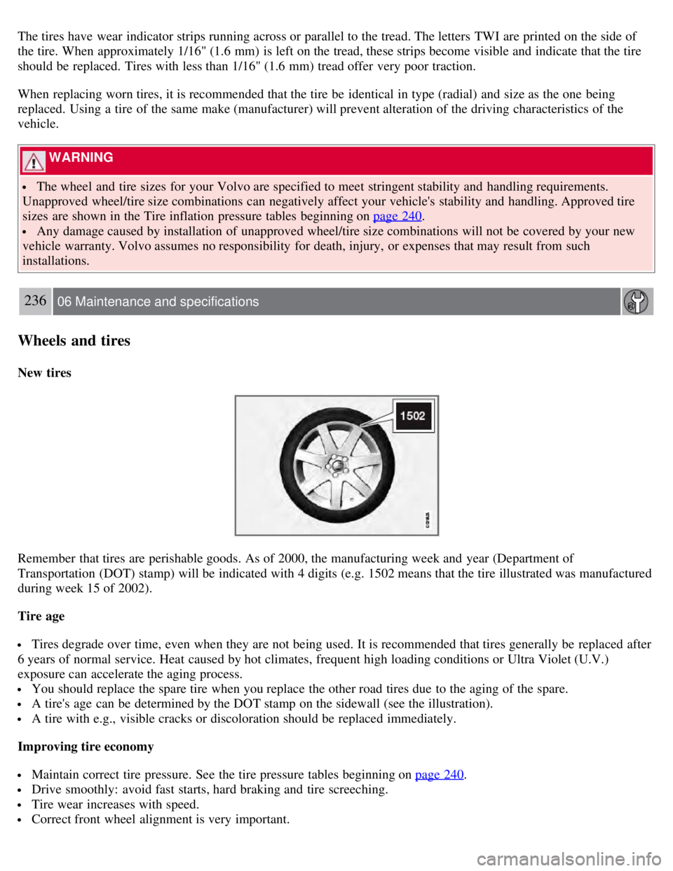
Remember that tires are perishable goods. As of 2000, the manufacturing week and year (Department of
Transportation (DOT) stamp) will be indicated with 4 digits (e.g. 1502 means that the tire illustrated was manufactured
during week 15 of 2002).
Tire age
Tires degrade over time, even when they are not being used. It is recommended that tires generally be replaced after
6 years of normal service. Heat caused by hot climates, frequent high loading conditions or Ultra Violet (U.V.)
exposure can accelerate the aging process.
You should replace the spare tire when you replace the other road tires due to the aging of the spare.
A tire's age can be determined by the DOT stamp on the sidewall (see the illustration).
A tire with e.g., visible cracks or discoloration should be replaced immediately.
Improving tire economy
Maintain correct tire pressure. See the tire pressure tables beginning on page 240.
Drive smoothly: avoid fast starts, hard braking and tire screeching.
Tire wear increases with speed.
Correct front wheel alignment is very important.
Page 236 of 275
Self supporting run flat tires
Certain models equipped with the Tire Pressure Monitoring System (TPMS) can also be equipped with self supporting
run flat tires.
Tires of this type have specially reinforced sidewalls that make it possible to continue driving in the event of a drop in
inflation pressure. Tires of this type are mounted on special rims.
NOTE
Self supporting run flat tires are only available in conjunction with TPMS.
If a self supporting run flat tire should lose inflation pressure, the yellow TPMS warning symbol (
) in the
instrument panel lights up to alert the driver, and a message will be shown in the text window in the instrument panel.
If this occurs, reduce vehicle speed to a maximum of 50 mph (80 km/h). The vehicle can be driven approximately 50
miles (80 km), or somewhat farther if the vehicle is not heavily loaded. The tire should be replaced as soon as
possible.
Hard braking and sudden steering maneuvers should be avoided.
In certain cases, it may be difficult to see which self supporting run flat tire is defective. To determine which tire is
damaged, check the inflation pressure of all four tires.
WARNING
Only specially trained persons should mount self supporting run flat tires.
If self supporting run flat tires are mounted, the vehicle must be equipped with a Tire Pressure Monitoring
System.
After a low pressure warning has been displayed, do not exceed 50 mph (80 km/h).
Avoid severe cornering and hard braking, and minimize the distance traveled before replacing the self supporting
run flat tire.
Self supporting run flat tires cannot be repaired. They must be replaced if damaged or punctured.
245 06 Maintenance and specifications
Wheels and tires
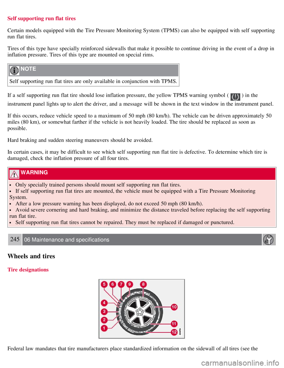
Tire designations
Federal law mandates that tire manufacturers place standardized information on the sidewall of all tires (see the
Page 246 of 275
Tire sealing system
Certain models are equipped with a tire sealing system that enables you to temporarily seal a hole in the tread surface
and reinflate a flat tire, or to adjust a tire's inflation pressure.
The system consists of an air compressor, a container for the sealing compound, wiring to connect the system to the
vehicle's electrical system via one of the 12-volt sockets, and a hose used to connect the system to the tire's inflation
valve.
The 12-volt sockets are located in the front tunnel console, on the rear side of the center console in the rear seat. See
page 185
.
Accessing the tire sealing system
The tire sealing system is stowed under the floor of the trunk. To access it:
1. Fold up the floor carpeting, starting at the rear and working forward.
2. Remove the retaining screws
3. Lift out the foam plastic block holding the jack and lug wrench.
4. Lift out the tire sealing system.
NOTE
The tire sealing system is only intended to seal holes on the tire's tread area, not the sidewall.
Tires with large holes or tears cannot be repaired with the tire sealing system.
WARNING
After using the tire sealing system, the vehicle should not be driven farther than approximately 120 miles (200
km).
Have the tire inspected by a qualified service technician as soon as possible to determine if it can be permanently
repaired or must be replaced.
The vehicle should not be driven faster than 50 mph (80 km/h) while using a tire that has been temporarily
repaired with the tire sealing system.
After using the tire sealing system, drive carefully and avoid abrupt steering maneuvers and sudden stops.
257 06 Maintenance and specifications
Wheels and tires
Tire sealing system -overview
Page 248 of 275
Skin: Wash affected areas of skin with soap and water. Get medical attention if symptoms occur.
Eyes: Flush with plenty of water for least 15 minutes, occasionally lifting the upper and lower eyelids. Get
medical attention if symptoms occur.
Inhalation: Move the person to fresh air. If irritation persists, get medical attention
1Certain markets only.
258 06 Maintenance and specifications
Wheels and tires
Inflating tires
The tire sealing system can be used to inflate the tires. To do so:
1. Park the car in a safe place.
2. The compressor should be switched off. Ensure that the on/off switch is in position 0 (the 0 side of the switch should
be pressed down).
3. Take out the electrical wire and hose.
4. Remove the valve cap from the tire's inflation valve and screw the hose connector onto the valve as tightly as
possible by hand.
5. Connect the electrical wire to the nearest 12-volt socket in the vehicle.
6. Start the vehicle's engine.
WARNING
The vehicle's engine should be running when the tire sealing system is used to avoid battery drain. Therefore, be
sure the vehicle is parked in a well ventilated place, or outdoors, before using the system.
Children should never be left unattended in the vehicle when the engine is running.
7. Check the tire's inflation pressure on the gauge. Switch off the compressor briefly to get a clear reading from the
pressure gauge.
8. Refer to the tables on pages 240 and 241
for the correct tire inflation pressure. If the tire needs to be inflated, start
the tire sealing system's compressor (press the on/off switch to position I ). If necessary, release air from the tire by
turning the air release knob counterclockwise.
CAUTION
The compressor should not be used for more than 10 minutes at a time to avoid overheating.
9. Turn off the compressor (press the on/off switch to position 0) when the correct inflation pressure has been reached.
10. Unscrew the hose from the tire's inflation valve and reinstall the valve cap.
11. Disconnect the electrical wire from the 12-volt socket.
Page 250 of 275
Contact with the sealing compound may cause skin irritation. If contact occurs, wash the affected area immediately
with soap and water.
5. Unscrew the orange cover over the bottle holder and unscrew the cap on the bottle of sealing compound.
NOTE
Do not break the seal on the bottle. This occurs automatically when the bottle is screwed into the holder.
6. Screw the bottle into the bottle holder.
WARNING
The bottle is equipped with a catch to keep it securely in place and help prevent sealing compound leakage. Once in
place, the bottle cannot be unscrewed. This must be done by a trained and qualified Volvo service technician.
7. Remove the valve cap from the tire's inflation valve and screw the tire sealing system's hose connector onto the
valve as tightly as possible by hand.
260 06 Maintenance and specifications
Wheels and tires
8. Connect the electrical wire to the nearest 12-volt socket in the vehicle.
9. Start the vehicle's engine.
WARNING
The vehicle's engine should be running when the tire sealing system is used to avoid battery drain. Therefore, be sure
the vehicle is parked in a well ventilated place, or outdoors, before using the system.
10. Start the tire sealing system's compressor by pressing the on/off switch to position I .
WARNING
Never stand next to the tire being inflated when the compressor is in operation.
If cracks, bubbles, etc. form on the tire, switch off the compressor immediately.
If there is visible damage to the sidewall or the rim, the tire cannot be repaired. The vehicle should not be driven if
this occurs. Contact a towing service or Volvo On Call Roadside Assistance if applicable.
NOTE
The air pressure gauge will temporarily show an increase in pressure to approximately 88 psi (6 bar) while the
sealing compound is being pumped into the tire. The pressure should return to a normal level after approximately 30
seconds.
11. Within seven minutes, inflate the tire to between 22-44 psi (1.8-3.0 bar). Switch off the compressor briefly to get a
clear reading from the pressure gauge.
Page 269 of 275

Infant seats36-37
Inflatable curtain27
Inflation pressure237-238
Inflation pressure tables240-241
Information lights74-77
Information symbol76
Inspection readiness210
Instrument lighting89
Instrument overview72-74
Instrument panel124-125
Integrated booster cushion45-47
Interior Air Quality System127, 131
Interior lighting93-94
ISOFIX anchors42
J
Jack
attaching 254
location of253
Jump starting 109
K
Key blade52
, 57-58
valet locking58
Keyless drive
location of antennas (pacemaker warning) 62
locking and unlocking the vehicle60- 61
starting the engine108
L
Labels
list of 268
location of267
Lane Departure Warning 174
LATCH anchors42
Leather care264
Lighting panel89
Load anchoring eyelets198
Loading the vehicle198-199, 247
roof loads200
Locking
automatic 63
from the inside63
from the outside63
glove compartment64
trunk64
Locking the vehicle 54