2008 VOLKSWAGEN BEETLE buttons
[x] Cancel search: buttonsPage 50 of 138
Downloaded from www.Manualslib.com manuals search engine Electrical controls on the front seats ~~~~~~~~~~~~-----------------------
®
651<-()590
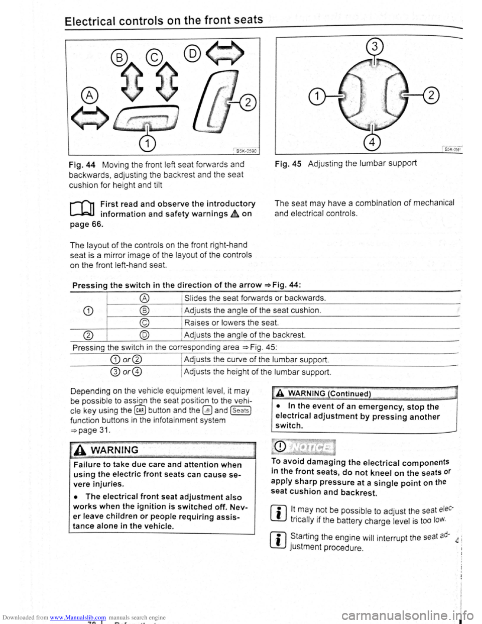
Fig. 44 Moving th e front left seat forwards and
backwards , ad j
usting the backrest and the seat
cushion for hei
ght and tilt
r-('n First read and observe the introductory
L-.lc:J.I information and safety warnings~ on
page 66.
The layout of the contro ls on the front r ight-hand
seat is a m irror image
of the layout of th e contro ls
on the front left-hand sea
t.
Fig. 45 Adju stin g the lumbar support
The seat may have a combination of mechanical
and electrical controls.
Pressing the switch in the direction of the arrow ~Fig. 44:
® Slides the seat forwards or backwards .
CD ® Adjusts the ang le of the seat cushion.
© Raises or lower s the seat.
@ @ Adjust s th e angle of the backrest.
Press ing the s witch in th e corresponding area
~Fig. 45:
CD or@ I Adjusts the curv e of the lumbar support.
@or@ I Ad justs the he ight of the lumbar support .
D epending on the veh ic le equ ipment leve l, it
may
be possib le to ass ign the seat pos it ion to the vehi
cle key using the @ill button and the~ and (seats]
funct ion buttons in the info ta inment system
~page 31.
~A WARNING
Failure to take due care and attention when
using the electric front seats can cause se
vere injuries.
• The electrical front seat adjustment also
works when the ignition is switched off. Nev
er leave children or people requiring assis
tance alone in the vehicle.
~"'A WARNING (Continued} --~ ~ -·-
• In the event of an emergency, stop the
electrical adjustment by pressing another
switch.
To avoid damaging the electrical components
in the front seats, do not kneel on the seats or
apply sharp pressure at a single point on the
seat cushion and backrest.
m lt.may ~Ot be poss ib le to adjust the seat eleC·
W tncally 1f the battery charge level is too loW.
m ~tarting the engine will interrupt the seat ad· 4 i
W JUStment procedure .
"7n I I
Page 64 of 138

Downloaded from www.Manualslib.com manuals search engine "Coming Home"
Switching on
Switching off
"Leaving Home"
Switch ing on
Switc h ing off
I Action
------Swit c h off the ignit io n .
- Operate the headlight flashe r for approximately one second ~page 106.
The Coming Home lights are switched on when the driver door is opened . The
swi tc h-off de lay starts when the last vehicle door or the tailgate has been closed
-Occurs automatica lly once the set switch-off delay has elapsed .
-Occurs automatica lly if another ve h icle door or the tailgate is opened within ap-
proximately 30 seco nds of it being swit ched on.
- Turn the
ligh t switc h to positio n 0.
- Swit ch o n the ignition .
Action
-Unl ock the vehicle when the ligh t senso r is in position AUTO and the twilight sen
sor that it is d ar k.
- Occ urs autom atically once the switch-off delay has elapsed .
- Lo ck
the vehicle.
-Turn the light switc h to positi on 0.
-Switch on the ignition .
Surround lighting in the exterior mirrors m The length of the switch-off delay can be ad
L!:J justed , o r the function can be switched on
and off, u sing the
(ill) button and the~ and (Light)
functio n buttons in the infota inment system
=:.page 31.
Th e surround lighting in the exterior mirrors ligh ts
up the area directly around
the doors while you are
ente ring or ex iting the vehicle . lt is sw itc h ed on
when th e ve hi cle is unlo cked, when opening the
driver door or wh en
the Coming Home or Leav ing
Hom e lighting function is ac tiv e .
If the veh icle is
eq uipp ed with a ligh t sensor , the surround lighting
i n th e exterior mirrors
will only be switched on
wh en it is dark.
m When the Com ing Home function is switched .
L!:J on, no acoustic warning will sound when the t
driver d oor is opened to remind you that a light is
still switched on.
Headlight range control, instrument and switch lighting
Fig. 83 Nex t to the stee ring wheel: head light
ra nge contr ol
CD and in strum ent and swit ch lighting
co ntr ol@
r-('n First read and observe the introductory
~ information and safety warnings ~ on
page 105.
112 Bofore the journey
Headlight range control
D epending on what level it is se t to, the head light
rang e co ntrol
:::.Fig . 83 CD adjusts the position of
the light cones in the head lights according to the
load that the vehi cle is carrying. This gives the driv·
er the best visibilit y possible and means that on
coming traffic
will not be dazzle d :::. &.
The hea dlights ca n on ly be adjust ed when the dip-
ped beam headlights are switched on. ~
t
Page 65 of 138
Downloaded from www.Manualslib.com manuals search engine To adjust, turn the control CD to:
-Set~ng I Vehicle load lev~la) -------
1
2
3
Fron t seats occupied and luggage
compa rtment
empty.
All seats occupied and luggage com
partment empty.
All sea ts occ upi ed and luggage com
partm ent fully loaded . Towing a trai le r
wit h a
lo w drawbar load .
Only the driver sea t occupi ed and lug
ga ge compartm ent fully load ed . Tow
ing a trai le r w ith maximum drawbar
l
oad.
a) If you have diff ere nt loads. you can select a positi on be
tween th e settings.
Dynamic headlight range control
Th ere is no control CD for headlight range if the ve
hicle
has dynamic headli ght control. The head light
r ange is
automatically adapted to suit the ve hicle
load level as soon as the headli ghts are switched
on~&.
Instrument and switch lighting
The brightness of the in strument and switch li gh t
ing can be adjusted using the @ill button and the
~and !Ltght] function buttons in the infot ainm ent
system
~page 31 .
Depending on the vehicle equipment level, it may
be possible to adjust the brightness of the instru
ment and switch lighting to suit your requirements
by turning control® when the headlights are
switched on.
Interior and reading lights
Instrument cluster lighting
The instrumen t cl uste r ligh ting sw it c hes off auto
mati cally
in darkness and at other times, e.g . when
driving through a tunnel. This is in tended to prompt
the driver to switch on the dipped beam so that the
v e hi cle' s rea r l
ights are swit c hed on ~page 109.
.A WARNING
-
Heavy objects in the vehicle can cause the
headlights to dazzle and distract other road
users. This can lead to accidents and serious
injuries.
• The light cone should always be adjusted
to the load level of the vehicle to ensure that
other road users are not dazzled.
A WARNING
A failure or malfunction in the dynamic head
light range control can cause the headlights
to dazzle or distract other road users. This
can lead to accidents and serious injuries.
• Proceed to a qualified workshop to have
the headlight range control checked immedi
I
ately. ~--------------- --------------------~
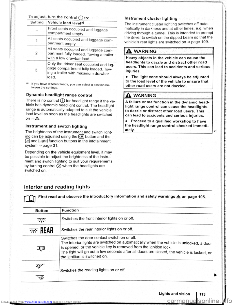
ClJ] First read and observe the introductory information and safety warnings & on page 105.
Button
~REAR
Function
Switches the front interior lights on or off.
Switches the rear interior lights on or off.
Switches the door contact switch on or off.
The interior lights are switche d on automatically when the vehicle is unlocked , a door
is opened, or the ve hicle key is removed from the ignition lock.
The light will go out a few seconds after all doors are closed, the vehicle is locked, or
the ignition is switched on.
/q'j/
---------j Switches the reading lights on or off.
Lights and vision 113
Page 69 of 138
Downloaded from www.Manualslib.com manuals search engine -~
....,
m
.u \ 1n j w v ip r 1 switched on auto
.1t1 ',111 if the front -.. ind creen wipers are
<::' t ' ' r ~ rse gear i eng ged.
m The automatic switch-on function when in. re
W verse gear can be switched on and off us1ng
the@] button and the G and (Mirror and wipers ) func
tion buttons in the infotainment system ~page 31.
ro Fi tread and observe the introductory information and safety warnings & on page 117.
iper response in various situat ions:
\.._e t e e d~ sat na•y
Healed a her jet
Headlight
hen sw1tched on , the wipers will temporarily be switched to the
ext setting down.
T e C hmatromc w1ll sw1tch to air recirculation mode for approxits ru -n a e l 30 seconds to prevent the smell of the windscreen wash-
a s t
er utd from entering the vehicle interior.
T e
rper in tervals are adjusted depending on the vehicle
speed. The faster the vehicle is travelling, the shorter the inter
a!
nses on
ward s the steering wheel when the dipped beam
headlights or main beam are switched on. Clean
off stubborn dirt (msects, etc.) from the headl ights
at regular intervals, for instance when filling the
tank .
In winter, you should remove any snow from the
headligh t w as her nozzles in the
bumper to keep
the headligh t washer system in work ing order. Re
move any ice with a de-icer spray.
r:l The w1per will try to wipe away any obstacles
L!J that are on the wind screen . The w 1per will
sop moving 1f the obstacle blocks its path . Re-
mo e the obstacle and swttch the wiper back on
agam
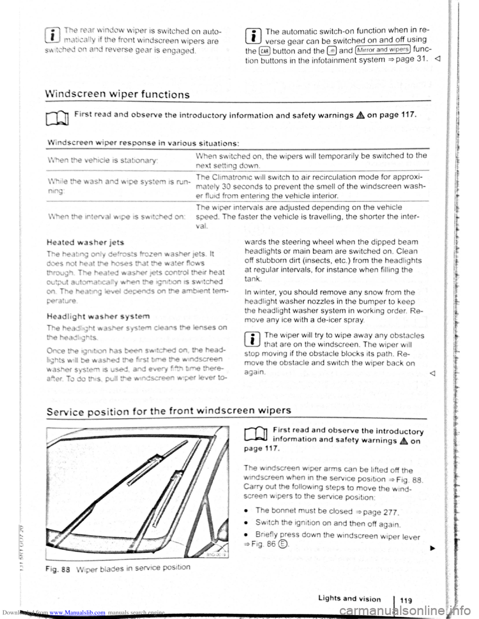
Service position for the front windscreen wipers
F ig . 88
2 -!.
r-T'n ~lr t rea~ and observe the introductory
L-Jr:J.J mformat1on and safety warnings on
page 117 .
Tt>e .vtndscreen Wlper arms can be h fted off the
ndsaeen when 10 the serv1ce pos1t1on ~ Ftg. 88.
Carry out e followtng s eps to move the w rnd
screen w1pers
t o the servtce pos1t1on
• The bonnet must be closed ~page 277.
• Swrtch the 1gntlton on and then off aga
1n
•
B ne y press down the wtndsc reen w1per le er
~F1g. 86 @.
Lights and vision 119
I 3£
Page 70 of 138

Downloaded from www.Manualslib.com manuals search engine Place the windscreen wiper arms back onto the
winds creen before driving away. With the ignition
swit ched on, briefly press the windscreen wiper
lever
down to bring the windscreen wiper arms
ba ck
to the original position.
Lifting the windscreen wiper blades
• Move the wiper arms to the service position be
fore lifting ~CD.
• When lifting a wiper arm hold it only by the wip
er blade mounting .
Rain sensor
1}®
c®
85K ·0419
Fig. 89 Windscreen wiper lever: setting rain sen
sor G)
r-('n First read and observe the introductory
L-J,::JJ information and safety warnings & on
page
117.
When the rain sensor is activated , it automatically
controls the frequency
of the wiper intervals, de
pending on the amount of rain ~ ,&. The sensitivity
of the rain sensor can be adjusted manually. Man
ual
wipe ~page 118 .
The automatic wipe function can be switched on
and off using the
(ill) button and the 0 and
[Mirror and wipers ] function buttons in the infotainment
system
~page 31.
Push the lever to the desired position ~Fig. 89:
® Deactivat es the rain sensor.
@ Rain sensor is active -automatic wipe when
necessary .
G) Adjusting the sensitivity of the rain sensor :
-
Switch to the right -high sensitivity.
-
Switch to the left -low sensitivity .
The rain sensor
will remain active after the ignition
is switched off and back on again and
will function
again
if the windscreen wiper lever is in position @
and if the vehicle is travelling at speeds higher
than 4 km/h
(2 mph).
• In order to prevent damage to the bonnet
and the windscreen
wiper arms, the wind
screen wiper arms should only be lifted when
in the service position.
• Always return the windscreen wiper arms to
the windscreen before starting your journey.
Fig. 90 Sensitive surface of the rain sensor
Changes to the functioning of the rain
sensor
Possible causes for faults and misinterpretations
concerning the sensitive surface~ Fig. 90 of the
rain sensor include:
• Damaged wiper blades: a film of water or
smears caused by damaged wiper blades
can in
crease the length of time for which the wipers are
switched on, shorten the length of the intervals be
tween wipes, or cause the wipers to run continu
ously.
• Insects: insects hitting the surface can cause
the wipers to be activated.
• Salt deposits : in winter, salt deposits can cause
the wiper to continue to wipe the windscreen when
it is almost dry.
• Soiling : dry dust, wax, windscreen coatings (lo·
tus effect) or detergent deposits (automatic car
wash) can cause the rain sensor to become less
sensitive and react too slowly or even not at all.
• Crack
in the windscreen : when the windscree~
is impacted by a stone, a wash cycle is triggered If ....
~he rain sensor is on . The rain sensor will then reg-,. ~
1ster the reduction in sensitivity of the surface and ~
120 I Before the journey _,}
~----~------------------~~
Page 91 of 138

Downloaded from www.Manualslib.com manuals search engine • When a vehi cle doo r is opened .
• When the TCS or ESC systems are taking cor
rective action.
• If the vehicle is sta tionary for longe r than ap
proximately
3 minutes .
~ ~~ .....
A WARNING
'"
Do not allow the images shown on the screen
to distract you from the traffic around you.
ParkPilot menu
r-('n First read and observe the i~troductory
l.-.l.:JJ information and safety warnmgs on
page 201.
ParkPilot settings in the infotainment
system menu
Switch on the ignition .
If necessary , switch on the infota inment system .
Function button: action
CD
Failure to observe thhe.ill
1
umbi~ated text messag.
es can lead to the ve tc e emg damaged .
1:1 lt can take a fe w seconds be for e the area
L!J scanned by the sensors ls displayed on the
screen
of the factory- fitted infot ainm ent system .
Press the@) button .
Touch the
G fu n ction button .
Touch the
(Parkmg and mAnoeuverin g) fun ction button.
Select the required settings in the ParkPilot
menu .
[10Act1vate automatically ): 1f the checkbox 1n the functio n button is t1cked ~.the mini display will be SWitched
on automat ically when the vehicle slowly approaches an obstacle located to the front. Touc h .
[10Act1vate automat1ca lly) again to switch off this function . After deactiva tion, the ParkPilot will no t be activated
automatically when the veh1cle approa ches an obstacle located to the front.
(Front volume): d1fferent volumes can be set separately fo r the acoustic warnings for the fron t by touching
the 8 or 8 funct ion butt ons , or by adJusting the control. ___
(Front p1tch): different pit ches can be set for the acoustic warnings for the front by touching the 0 or G
fun ction buttons , o r by adjust1ng the control.
(Rear volume) : different volumes can be set for the acoustic warnings for the rear by touchtng the 0 or G
function buttons. o r by adjusting the control. _
(Rear p1tc h ): different pitches can be set for the acoust ic warmngs for the rear by tou ch ing the 0 or 8 tunc·
tio n buttons . o r by adjusting the control. _
~~==~==~~~~-=~~--~~~-----------------------------~---(AudiO volume reduct1on): settmg the level to which the infota inment system volume should be reduced when
the ParkPilot 1s act1ve.
Audio volume reduction
Menu option Explanation
r.O:-ff ___________________ -+-=T~he::.._ . ..:.v.:..ol:.:u::.m.:..:e~i~n:,:th~e~~n~fotamment sytem is not reduced. __ ----
Low Th e volume in the infota1nmen t sytem IS red~c;;d ~~~~tly. _..
Medium The volume in the infota inment syt e m is red uced to ~~~d1unl. -
Strong Th e 1 . - -11111un1. vo ume m the infota1nmen t sytem is reduced to a 11111
Muting the ParkPilot
You can mute the acoustic signals from the ParkPi
lot by touching the (!) fun ction button on the info
tainment system screen. Pr ess the functio n button
again to switch the acoustic warnings back on.
206 While driving
park Pilot The mute setting will be ca ncelled 1f the rn·
system is switched off and on again . Error w a
ings canno t be swi tc h ed off.
. d off ntJfl'
If the ParkPilot display has been sw1tcl'~9 et·
ually
and ParkP1Iot remains act1ve. the nnlt s t
tlng is also cance lled .
Page 103 of 138
Downloaded from www.Manualslib.com manuals search engine ~ ·, ~ )
' { q
Indicator lamp
Ut up Possible cause
CCS or the speed limiter is controll ing the speed.
several warning and indicato r l amps will light up
briefly as a fun cti o nal check whe n the ig nitio n is
switc h e d on . Th ey will switch off after a few sec
onds.
'
A WARNING .
Failure to observe illuminated warning lamps
and text messages can lead to your vehicle
breaking down in traffic, and can cause acci
dent and serious injury.
• Never ignore any illuminated warning
lamps or text messages.
Failure
to observe illuminated indicator lamps
and text messages can lead to your vehicle be
ing damaged.
m If the CCS, ACC or speed limite r were
W switched on when the ignition was switc h e d
off, the
CCS or ACC will be switched on autom ati
cally the nex t tim e th e ignition is switc hed on. How
ever, no speed is stor ed. The speed limiter's las t
set speed remains stored.
r:i Displays can vary as different ve rsions of th e
W instrument cluster are availab le .
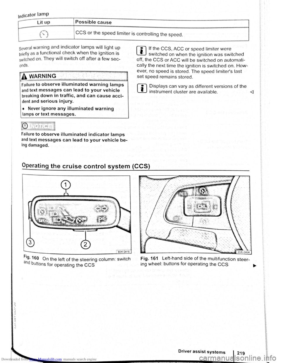
Fig. 160 On the left of the steering column: swit c h
and buttons for operating the CCS
Fig. 161 Left-hand side of the multifunct ion steer-
ing wheel : buttons for operating the
CCS ~
Driver assist systems
Page 107 of 138
Downloaded from www.Manualslib.com manuals search engine ~
A WARNING ...
~re to observe illuminated w~rning lan1ps
d text messages can lead to your vehicle
an tt· d breaking down in tra 1C, a n can cause acci-
dent and serious injury.
• Never ignore any Illuminated w arning
lamps or text messages,
CD I'. [
Failure to observe illuminated indicator lamps
and text messages can lead to your vehicle be-
ing damaged.
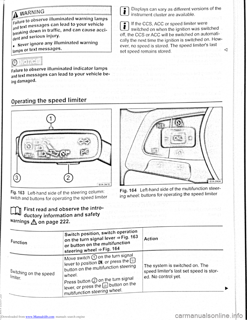
Operating the speed limiter
B~l\·04 16
Fi~. 163 Left-hand side of the steering column :
SWitch and buttons for operating the speed limiter
[Q] First read and observe the intro-
ductory information and safety
warnings ~ on page 222.
rn
• ~is plc y c n vary as different vers ions of the
1ns trum nt clu t rare availab le .
rn
• If tl~ CCS, ACC or spe ed limit er w ere
w1tch d on wh n the ignition was switched
ff, the CCS or ACC will be switched on automati
c
lly the n xt time the ignition is switched on. How-
v
r, n o sp d is stored . The speed lim iter's last
s t p d r mains s tored.
ing wheel : buttons for operating the speed limiter
Function
Switch position, switch operation
on the turn signal lever ~Fig. 163
or button on the multifunction
steering wheel ~Fig. 164
Action
s . r w.11Ching on the speed 1rn1ter.
Move switch CD on the turn signal
lever to position
ON. or press the ~
button on the multifunction steenng
wheel.
The system is switched on. The
speed li miter's las t set speed is st or
ed. No control yet. Press button ®on the turn signal
lever ,
or press the 0 button on the
----------------~m~u~lti~fu~n~c~ti~o~n~s~te~e~r~in~g~w~he~e~I~·------J----------------------------~