Page 514 of 580
514 5-2. Steps to take in an emergency
Emergency start functionWhen the hybrid system does not start, the following steps can be
use as an interim measure to start the hybrid system if the “POWER”
switch is functioning normally.
Set the parking brake.
Shift the shift lever to P.
Turn the “POWER” switch to the ACCESSORY mode.
Push and hold the “POWER” switch about 15 seconds while
depressing the brake pedal firmly.
Even if the hybrid system can be started using the above steps, the
system may be malfunctioning. Ha ve the vehicle checked by your
Toyota dealer.
■ The interior lights and headlights do not turn on, or the horn
does not sound.
One of the following may be the cause of the problem.
●One or both of the 12-volt ba ttery terminals may be discon-
nected.
● The 12-volt battery may be discharged. ( P. 519)
Contact your Toyota dealer if the problem cannot be repaired, or if
repair procedures are unknown.
STEP1
STEP2
STEP3
STEP4
Page 520 of 580

520 5-2. Steps to take in an emergency
■Avoiding a discharged 12-volt battery
●Turn off the headlights and the audio system while the hybrid system is
off.
● Turn off any unnecessary electrical components when the vehicle is run-
ning at a low speed for an extended period, such as in heavy traffic, etc.
■ When the 12-volt battery is removed or discharge
●The hybrid system may not start. ( P. 436)
● The power back door must be initialized ( P. 7 9 )
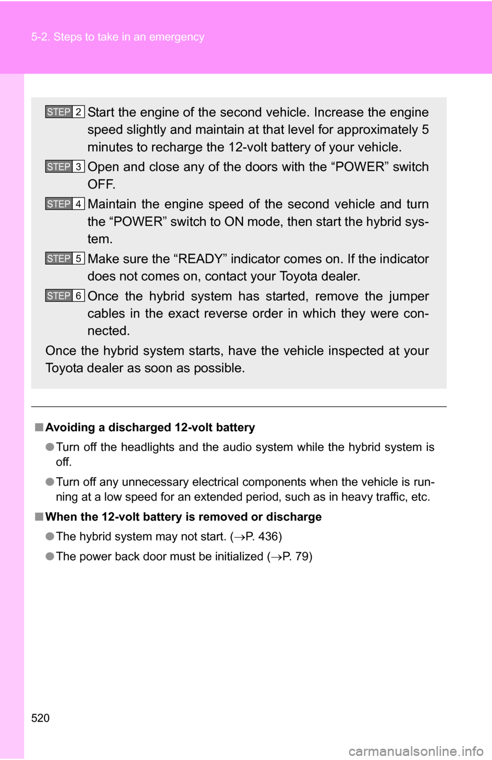
Start the engine of the second vehicle. Increase the engine
speed slightly and maintain at that level for approximately 5
minutes to recharge the 12-v olt battery of your vehicle.
Open and close any of the doors with the “POWER” switch
OFF.
Maintain the engine speed of the second vehicle and turn
the “POWER” switch to ON mode, then start the hybrid sys-
tem.
Make sure the “READY” indicator comes on. If the indicator
does not comes on, contact your Toyota dealer.
Once the hybrid system has started, remove the jumper
cables in the exact reverse order in which they were con-
nected.
Once the hybrid system starts, ha ve the vehicle inspected at your
Toyota dealer as soon as possible.STEP2
STEP3
STEP4
STEP5
STEP6
Page 521 of 580

5
When trouble arises
521
5-2. Steps to take in an emergency
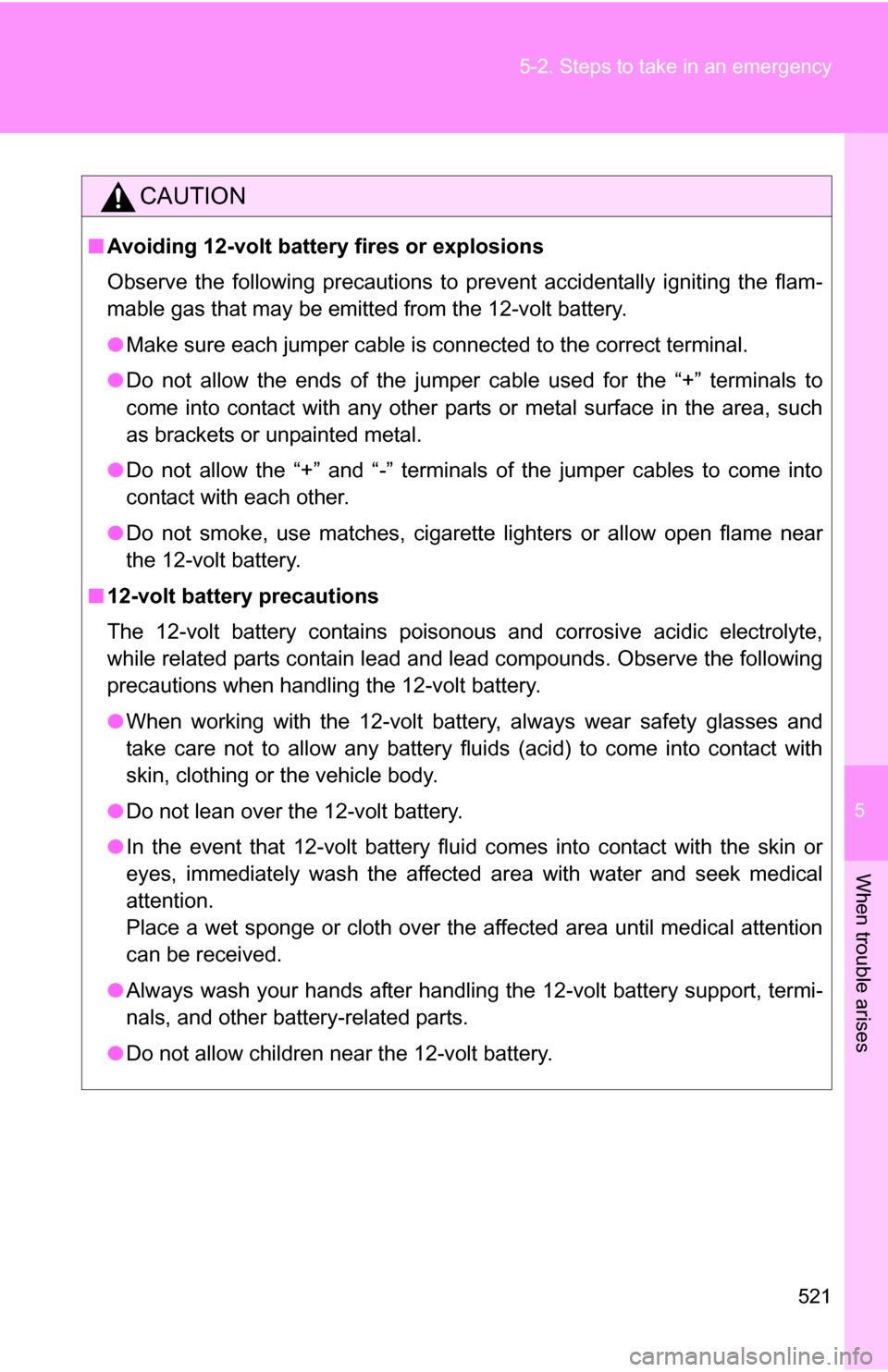
CAUTION
■
Avoiding 12-volt battery fires or explosions
Observe the following precautions to prevent accidentally igniting the flam-
mable gas that may be emitted from the 12-volt battery.
●Make sure each jumper cable is connected to the correct terminal.
● Do not allow the ends of the jumper cable used for the “+” terminals to
come into contact with any other parts or metal surface in the area, such
as brackets or unpainted metal.
● Do not allow the “+” and “-” terminals of the jumper cables to come into
contact with each other.
● Do not smoke, use matches, cigarette lighters or allow open flame near
the 12-volt battery.
■ 12-volt battery precautions
The 12-volt battery contains poisonous and corrosive acidic electrolyte,
while related parts contain lead and lead compounds. Observe the following
precautions when handling the 12-volt battery.
●When working with the 12-volt battery, always wear safety glasses and
take care not to allow any battery fluids (acid) to come into contact with
skin, clothing or the vehicle body.
● Do not lean over the 12-volt battery.
● In the event that 12-volt battery fluid comes into contact with the skin or
eyes, immediately wash the affected area with water and seek medical
attention.
Place a wet sponge or cloth over the affected area until medical attention
can be received.
● Always wash your hands after handling the 12-volt battery support, termi-
nals, and other battery-related parts.
● Do not allow children near the 12-volt battery.
Page 536 of 580
536 6-1. Specifications
Ignition system
Electrical system
Spark plug
Make
GapDENSO SK20R11
NGK IFR6A11
0.043 in. (1.1 mm)
NOTICE
■
Iridium-tipped spark plugs
Use only iridium-tipped spark plugs. Do not adjust spark plug gap.
12-volt battery
Open voltage* at
68 F (20 C): 12.6 12.8 V Fully charged
12.2 12.4 V Half charged
11 . 8
12.0 V Discharged
(*: Voltage is checked 20 minutes
after the hybrid system and all the
lights are turned off)
Charging rates 5 A max.
Page 543 of 580
543
6-1. Specifications
6
Vehicle specifications
Light bulbs
A: H11 halogen bulbs
B: Wedge base bulbs (amber)
C: HB2 halogen bulbs D: Wedge base bulbs (clear)
*: If equipped
Light BulbsBulb No.WTy p e
ExteriorHeadlights
60/55 C
Front turn signal lights 21 B
Parking/front side marker lights 5B
Front fog lights* 55 A
Rear turn signal lights 21 B
Back-up lights 16 D
Stop/tail and rear side marker
lights
21/5 D
License plate lights 5D
Outer foot lights* 5D
Interior Vanity lights
8D
Personal/interior lights (front) 5D
Personal/interior lights (center)* 5D
Interior light 8D
Door courtesy lights 5D
Page 544 of 580

544
6-1. Specifications
Fuel infor mation
■Fuel tank opening fo r unleaded gasoline
To help prevent incorrect fueling, your Toyota has a fuel tank opening that
only accommodates the special nozzle on unleaded fuel pumps.
■ If your engine knocks
●Consult your Toyota dealer.
● You may occasionally notice light knocking for a short time while acceler-
ating or driving uphill. This is normal and there is no need for concern.
■ Gasoline quality
In very few cases, driveability problems may be caused by the brand of gas-
oline you are using. If driveability problems persist, try changing the brand of
gasoline. If this does not correct the problem, consult your Toyota dealer.
■ Gasoline quality standards
●Automotive manufacturers in the US, Europe and Japan have developed
a specification for fuel quality called World-Wide Fuel Charter (WWFC)
that is expected to be applied worldwide.
● The WWFC consists of four categories that are based on required emis-
sion levels. In the US, category 4 has been adopted.
● The WWFC improves air quality by lowering emissions in vehicle fleets,
and customer satisfaction through better performance.
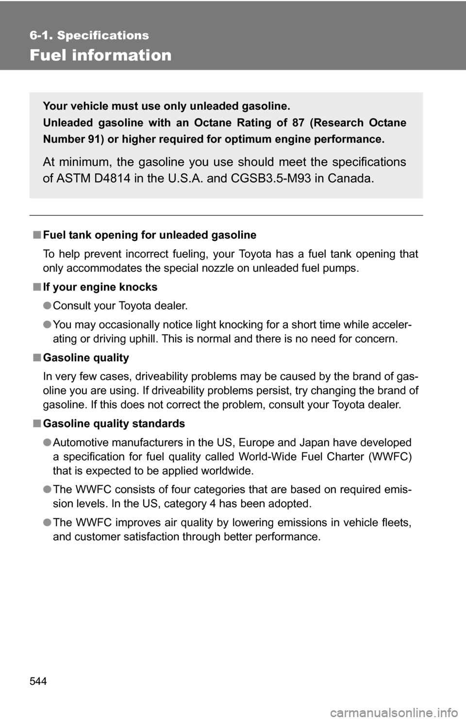
Your vehicle must use only unleaded gasoline.
Unleaded gasoline with an Octane Rating of 87 (Research Octane
Number 91) or higher required for optimum engine performance.
At minimum, the gasoline you us e should meet the specifications
of ASTM D4814 in the U.S.A. and CGSB3.5-M93 in Canada.
Page 556 of 580

556 6-1. Specifications
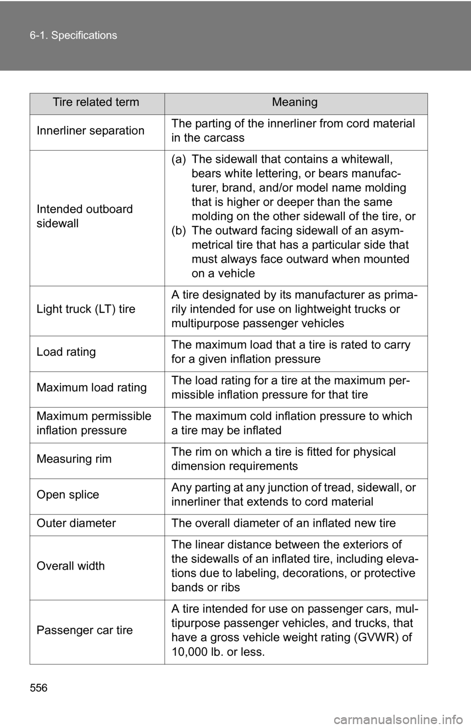
Tire related termMeaning
Innerliner separation The parting of the innerliner from cord material
in the carcass
Intended outboard
sidewall (a) The sidewall that contains a whitewall,
bears white lettering, or bears manufac-
turer, brand, and/or model name molding
that is higher or deeper than the same
molding on the other sidewall of the tire, or
(b) The outward facing sidewall of an asym- metrical tire that has a particular side that
must always face outward when mounted
on a vehicle
Light truck (LT) tire A tire designated by its manufacturer as prima-
rily intended for use on lightweight trucks or
multipurpose passenger vehicles
Load rating The maximum load that a tire is rated to carry
for a given inflation pressure
Maximum load rating The load rating for a tire at the maximum per-
missible inflation pressure for that tire
Maximum permissible
inflation pressure The maximum cold inflation pressure to which
a tire may be inflated
Measuring rim The rim on which a tire is fitted for physical
dimension requirements
Open splice Any parting at any junction of tread, sidewall, or
innerliner that extends to cord material
Outer diameter The overall diameter of an inflated new tire
Overall width The linear distance between the exteriors of
the sidewalls of an inflated tire, including eleva-
tions due to labeling, decorations, or protective
bands or ribs
Passenger car tire A tire intended for use on passenger cars, mul-
tipurpose passenger vehicles, and trucks, that
have a gross vehicle weight rating (GVWR) of
10,000 lb. or less.
Page 560 of 580
560 6-2. Customization
Wireless
remote con-
trol
(
P. 65)Wireless remote control ON OFF
Unlocking operation
Driver's door
unlocked in one step, all doors
unlocked in two steps All doors
unlocked in one step
Automatic door lock
function to be activated
if door is not opened
after being unlocked ON OFF
Time elapsed before
automatic door lock
function is activated if
door is not opened after
being unlocked 60 seconds
30 seconds
120 seconds
Operation signal
(Emergency flashers) ON OFF
Door lock buzzer ON OFF
Operation signal
(Buzzer) ON OFF
Panic function ON OFF
Automatic
light control
system
( P. 200) Light sensor sensitivity Level 3 Level 1 to 5
Time elapsed before
headlights automati-
cally turn off after doors
are closed
30 seconds0 second
60 seconds
90 seconds
Lights
(
P. 200) Daytime running light
system (U.S.A. only)
ON OFF
Alarm sys-
tem
(
P. 124) Time elapsed before
the alarm is set
14 seconds 30 seconds
ItemFunctionDefault settingCustomized
setting