Page 156 of 440
156 2-4. Using other driving systems
■Fine adjustment of the set speed
Adjustment of the set speed by approximately 1.0 mph (1.6 km/h) can be
made by lightly pressing the lever up or down and releasing it.
■ Cruise control can be set when
●The shift lever is in D.
● Vehicle speed is between approximately 25 mph and 125 mph (40 km/h
and 200 km/h).
■ Accelerating
The vehicle can be accelerated normally.
■ Automatic cruise control cancellation
The set speed is automatically canceled in any of the following situations.
●Actual vehicle speed falls more than 10 mph (16 km/h) below the preset
vehicle speed.
At this time, the memorized set speed is not retained.
● Actual vehicle speed is below 25 mph (40 km/h).
● VSC is activated.
■ Canceling and resuming regular acceleration
Cancel
Pull the lever towards you to
cancel cruise control.
The speed setting is also can-
celed when the brakes are
applied.
Resume
To resume cruise control and
return to the set speed, push
the lever up.
Page 282 of 440
282 4-2. Maintenance
Vehicle interior
ItemsCheck points
Accelerator pedal • Moves smoothly (without uneven
pedal effort or catching)?
Transmission “Park” mechanism • Can the vehicle be held securely
on an incline with the shift lever in
P?
Brake pedal • Moves smoothly?
• Does it have appropriate clear-
ance and correct amount of free
play?
Brakes • Not pull to one side when
applied?
• Loss of brake effectiveness?
• Spongy feeling brake pedal?
• Pedal almost touches floor?
Head restraints • Move smoothly and lock
securely?
Indicators/buzzers • Function properly?
Lights • Do all the lights come on?
Parking brake • Moves smoothly?
• Can hold the vehicle securely on
an incline?
Seat belts • Does the seat belt system oper-
ate smoothly?
• Are the belts undamaged?
Seats • Do the seat controls operate
properly?
Steering wheel • Moves smoothly?
• Has correct free play?
• No strange noises?
Page 298 of 440
298 4-3. Do-it-yourself maintenance
Radiators and condenserCheck the radiators and condenser and remove any foreign objects.
If any of the above parts are extr emely dirty or you are not sure of
their condition, have your vehicl e checked by your Toyota dealer.
Brake fluid
■ Checking fluid level
The brake fluid level should be
between the “MAX” and “MIN”
lines on the tank.
If the level is low, take your vehi-
cle to a Toyota dealer as soon as
possible. Do not drive your vehi-
cle if the red brake system warn-
ing light is on. Call a Toyota
dealer for assistance.
CAUTION
■The radiators and condenser may be hot after driving
Do not touch the radiators or condenser, as they may be hot and may be
burned.
CAUTION
■ When filling the reservoir
Take care because brake fluid can harm your hands or eyes and damage
painted surfaces.
If fluid gets in your eyes, flush your eyes with clean water immediately.
If you still experience discomfort, see a doctor.
Page 299 of 440
299
4-3. Do-it-yourself maintenance
4
Maintenance and care
Washer fluid
Add washer fluid in the following
situations.
●Any washer does not work.
● The warning message
appears on the multi-informa-
tion display.
NOTICE
■If the fluid level is low or high
It is normal for the brake fluid level to go down slightly as the brake pads
wear or when the fluid level in the accumulator is high.
If the reservoir needs frequent refilling, it may indicate a serious pro\
blem.
NOTICE
■Do not use any fluid other than washer fluid
Do not use soapy water or engine antifreeze instead of washer fluid.
Doing so may cause streaking on the vehicle’s painted surfaces.
■ Diluting washer fluid
Dilute washer fluid with water as necessary.
Refer to the freezing temperatures listed on the washer fluid tank.
Page 329 of 440

329
4-3. Do-it-yourself maintenance
4
Maintenance and care
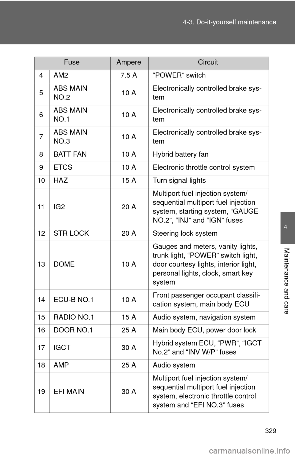
4 AM2
7.5 A “POWER” switch
5 ABS MAIN
NO.2 10 AElectronically controlled brake sys-
tem
6 ABS MAIN
NO.1 10 AElectronically controlled brake sys-
tem
7 ABS MAIN
NO.3 10 AElectronically controlled brake sys-
tem
8 BATT FAN 10 A Hybrid battery fan
9 ETCS 10 A Electronic throttle control system
10 HAZ 15 A Turn signal lights
11 IG2 20 AMultiport fuel injection system/
sequential multiport fuel injection
system, starting system, “GAUGE
NO.2”, “INJ” and “IGN” fuses
12 STR LOCK 20 A Steering lock system
13 DOME 10 AGauges and meters, vanity lights,
trunk light, “POWER” switch light,
door courtesy lights, interior light,
personal lights, clock, smart key
system
14 ECU-B NO.1 10 A Front passenger occupant classifi-
cation system, main body ECU
15 RADIO NO.1 15 A Audio system, navigation system
16 DOOR NO.1 25 A Main body ECU, power door lock
17 IGCT 30 AHybrid system ECU, “PWR”, “IGCT
No.2” and “INV W/P” fuses
18 AMP 25 A Audio system
19 EFI MAIN 30 AMultiport fuel injection system/
sequential multiport fuel injection
system, electronic throttle control
system and “EFI NO.3” fuses
FuseAmpereCircuit
Page 332 of 440
332 4-3. Do-it-yourself maintenance
■Under the instrument panel
FuseAmpereCircuit
1 RR DOOR RH 25 A Rear right power window
2 RR DOOR LH 25 A Rear left power window
3 FUEL OPN 7.5 A Fuel filter door opening system
4 FR FOG 15 A No circuit
5 OBD 7.5 A On-board diagnosis system
6 ECU-B NO.2 7.5 A No circuit
7 STOP 10 A Stop lights, high mounted stop-
light, shift lock control system, mul-
tiport fuel injection system/
sequential multiport fuel injection
system, main body ECU, electroni-
cally controlled brake system, elec-
tronic throttle control system
8 TI&TE 30 A No circuit
9 AM1 7.5 A Starting system, multiport fuel
injection system/sequential multi-
port fuel injection system
10 A/C 7.5 A Air conditioning system
11 PWR 25 A Power windows
Page 333 of 440

333
4-3. Do-it-yourself maintenance
4
Maintenance and care
12 DOOR NO.2 25 A Main body ECU
13 S/ROOF 30 A Electric moon roof
14 TAIL 15 A
Front side marker lights, tail lights,
rear side marker lights, license
plate lights
15 PANEL 7.5 A Navigation system, seat heaters,
emergency flashers, air condition-
ing system, audio system, clock,
glove box light, instrument panel
lights, steering switches
16 ECU IG NO.1 10 A Main body ECU, electric moon
roof, tire pressure warning system,
auto anti-glare inside rear view mir-
ror, starting system, navigation sys-
tem
17 ECU IG NO.2 7.5 A Electronically controlled brake sys-
tem, electric power steering sys-
tem, shift lock control system
18 A/C NO.2 10 A Air conditioning system, rear win-
dow defogger
19 WASH 10 A Windshield wipers and washer
20 S-HTR 20 A Seat heaters
21 GAUGE NO.1 10 A Emergency flashers, back-up lights
22 WIP 25 A Windshield wipers and washer
23 H-LP LVL 7.5 A No circuit
24 INJ 15 A Multiport fuel injection system/
sequential multiport fuel injection
system
FuseAmpereCircuit
Page 348 of 440

348
5-2. Steps to take in an emergency
If a war ning light tur ns on or a war ning buzzer sounds...
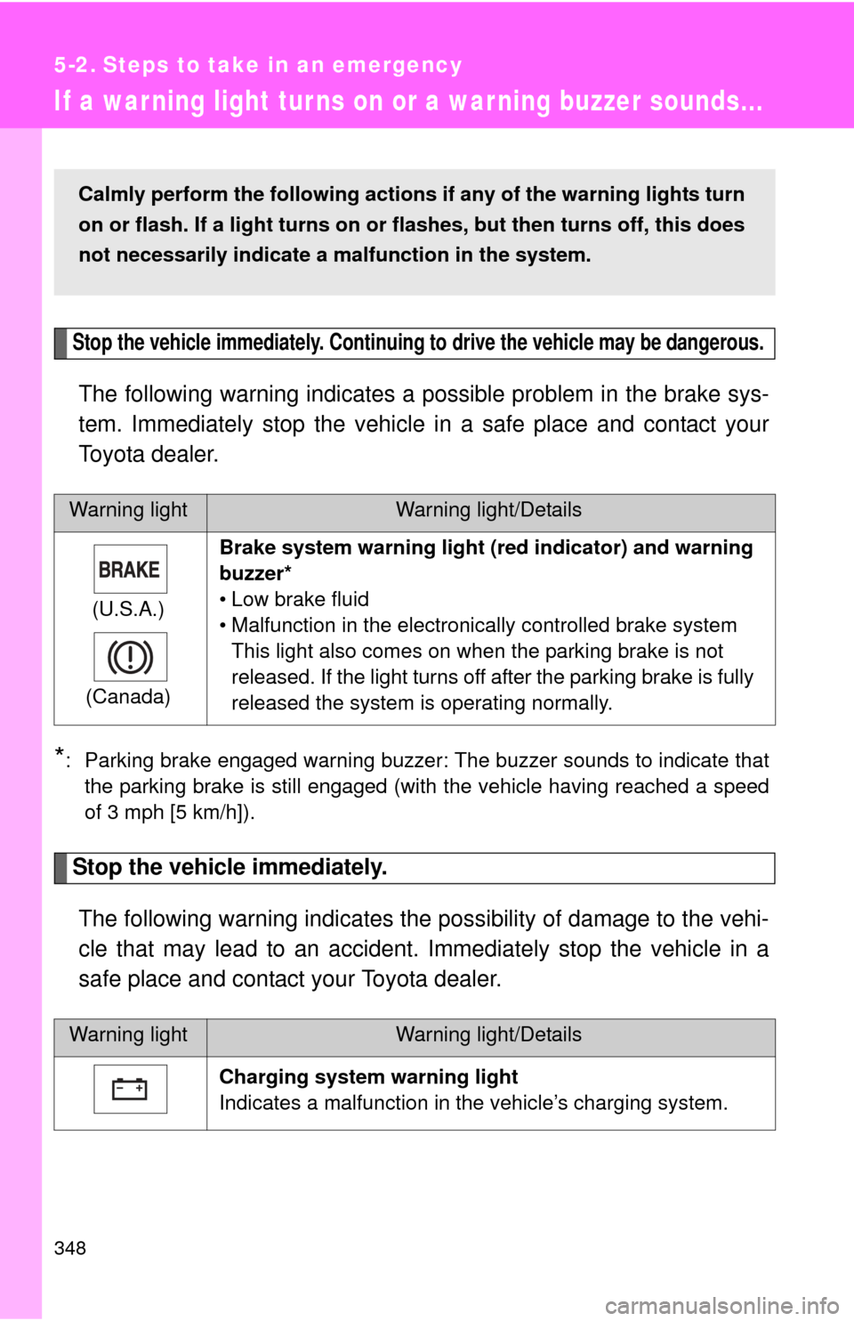
Stop the vehicle immediately. Continuing to drive the vehicle may be dangerous.
The following warning indicates a possible problem in the brake sys-
tem. Immediately stop the vehicle in a safe place and contact your
Toyota dealer.
*: Parking brake engaged warning buzzer: The buzzer sounds to indicate that the parking brake is still engaged (with the vehicle having reached a speed
of 3 mph [5 km/h]).
Stop the vehicle immediately.
The following warning indicates the possibility of damage to the vehi-
cle that may lead to an accident. Immediately stop the vehicle in a
safe place and contact your Toyota dealer.
Warning lightWarning light/Details
(U.S.A.)
(Canada) Brake system warning light (r
ed indicator) and warning
buzzer*
• Low brake fluid
• Malfunction in the electronically controlled brake system This light also comes on when the parking brake is not
released. If the light turns off after the parking brake is fully
released the system is operating normally.
Warning lightWarning light/Details
Charging system warning light
Indicates a malfunction in the vehicle’s charging system.
Calmly perform the following actions if any of the warning lights turn
on or flash. If a light turns on or flashes, but then turns off, this does
not necessarily indicate a malfunction in the system.