2008 TOYOTA AVALON roof
[x] Cancel search: roofPage 92 of 452

92 1-7. Safety information
AVALON_U_(L/O_0802)
CAUTION
●If the vinyl cover is put on the area where the SRS knee airbag will deploy,
be sure to remove it.
● Do not use seat accessories which cover the parts where the SRS side
airbags inflate as they may interf ere with inflation of the airbags.
● Do not strike or apply significant levels of force to the area of the SRS air-
bag components shown on P. 83. Doing so can cause the SRS airbags to
malfunction.
● Do not touch any of the component parts immediately after the SRS air-
bags have deployed (inflated) as they may be hot.
● If breathing becomes difficult after the SRS airbag has deployed, open a
door or window to allow fresh air in, or leave the vehicle if it is safe to do
so. Wash off any residue as soon as possible to prevent skin irritation.
● If the areas where the SRS airbags are stored, such as the steering wheel
pad and front and rear pillar garnish, are damaged or cracked, have them
replaced by your Toyota dealer.
■ Modification and disposal of SRS airbag system components
Do not dispose of your vehicle or perform any of the following modifications
without consulting your Toyota dealer. The SRS airbag may malfunction or
deploy (inflate) accidentally, causing death or serious injury.
● Installation, removal, disassembly and repair of the SRS airbags
● Repairs, modifications, removal or replacement of the steering wheel,
instrument panel, dashboard, seats or seat upholstery, front, side and rear
pillars or roof side rail
● Repairs or modifications of the front fender, front bumper, or side of the
occupant compartment
● Installation of snow plows, winches, etc. to the front grille (bull bars, kan-
garoo bar etc.)
● Modifications to the vehicle’s suspension system
● Installation of electronic devices such as mobile two-way radios or CD
players
● Modifications to your vehicle for a person with a physical disability
Page 101 of 452

101
1-7. Safety information
1
Before driving
AVALON_U_(L/O_0802)
CAUTION
■
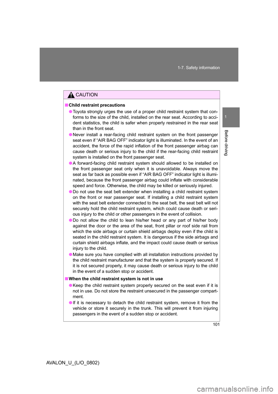
Child restraint precautions
● Toyota strongly urges the use of a proper child restraint system that con-
forms to the size of the child, installed on the rear seat. According to acci-
dent statistics, the child is safer when properly restrained in the rear seat
than in the front seat.
● Never install a rear-facing child restraint system on the front passenger
seat even if “AIR BAG OFF” indicator light is illuminated. In the event of an
accident, the force of the rapid inflation of the front passenger airbag can
cause death or serious injury to the child if the rear-facing child restraint
system is installed on the front passenger seat.
● A forward-facing child restraint system should allowed to be installed on
the front passenger seat only when it is unavoidable. Always move the
seat as far back as possible even if “A IR BAG OFF” indicator light is illumi-
nated, because the front passenger airbag could inflate with considerable
speed and force. Otherwise, the child may be killed or seriously injured.
● Do not use the seat belt extender when installing a child restraint system
on the front or rear passenger seat. If installing a child restraint system
with the seat belt extender connected to the seat belt, the seat belt will not
securely hold the child restraint system, which could cause death or seri-
ous injury to the child or other passengers in the event of collision.
● Do not allow the child to lean his/her head or any part of his/her body
against the door or the area of the seat, front pillar or roof side rail from
which the side airbags or curtain shield airbags deploy even if the child is
seated in the child restraint system. It is dangerous if the side airbags and
curtain shield airbags inflate, and the impact could cause death or serious
injury to the child.
● Make sure you have complied with all installation instructions provided by
the child restraint manufacturer and that the system is properly secured. If
it is not secured properly, it may cause death or serious injury to the child
in the event of a sudden stop or accident.
■ When the child restrain t system is not in use
● Keep the child restraint system properly secured on the seat even if it is
not in use. Do not store the restraint unsecured in the passenger compart-
ment.
● If it is necessary to detach the child restraint system, remove it from the
vehicle or store it securely in the trunk. This will prevent it from injuring
passengers in the event of a sudden stop or accident.
Page 285 of 452

285
3-6. Other interior features
3
Interior features
AVALON_U_(L/O_0802)
Wait a few seconds until the compass direction is displayed.
The calibration is complete.
■
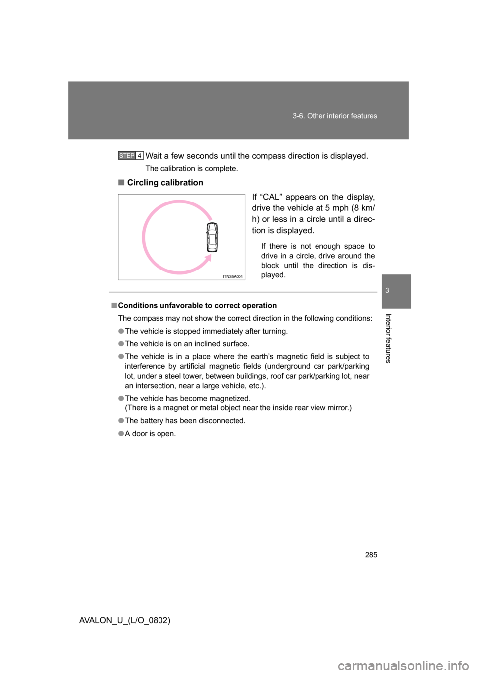
Circling calibration
If “CAL” appears on the display,
drive the vehicle at 5 mph (8 km/
h) or less in a circle until a direc-
tion is displayed.
If there is not enough space to
drive in a circle, drive around the
block until the direction is dis-
played.
STEP4
■Conditions unfavorable to correct operation
The compass may not show the correct direction in the following conditions:
● The vehicle is stopped immediately after turning.
● The vehicle is on an inclined surface.
● The vehicle is in a place where the earth’s magnetic field is subject to
interference by artificial magnetic fields (underground car park/parking
lot, under a steel tower, between buildings, roof car park/parking lot, near
an intersection, near a large vehicle, etc.).
● The vehicle has become magnetized.
(There is a magnet or metal object near the inside rear view mirror.)
● The battery has been disconnected.
● A door is open.
Page 286 of 452

286 3-6. Other interior features
AVALON_U_(L/O_0802)
CAUTION
■While driving
Do not adjust the display.
Be sure to adjust the display only when the vehicle is stopped.
■ When doing the circling calibration
Be sure to secure a wide space, and watch out for people and vehicles in the
neighborhood. Do not violate any local traffic rules while performing circling
calibration.
NOTICE
■To avoid the compass malfunctions
Do not place magnets or any metal objects near the inside rear view mirror.
Doing this may cause a malfunction of the compass sensor.
■ To ensure normal operation of the compass
● Do not perform circling calibration of the compass in a place where the
earth’s magnetic field is subject to inte rference by artificial magnetic fields.
● During calibration, do not operate electric systems (moon roof, power win-
dows, etc.) as they may interfere with the calibration.
Page 288 of 452

288
AVALON_U_(L/O_0802)
4-1. Maintenance and care
Cleaning and protecting the vehicle exterior
Perform the following to protect the vehicle and maintain it in prime
condition.
● Working from top to bottom, liber ally apply water to the vehicle
body, wheel wells and underside of the vehicle to remove any
dirt and dust.
Wash the vehicle body using a sponge or soft cloth, such as a cham-
ois.
● For hard-to-remove marks, use car wash soap and rinse thor-
oughly with water.
● Wipe away any water.
● Wax the vehicle when the waterproof coating deteriorates.
If water does not bead on a clean surface, apply wax when the vehicle
body is cool.
Page 350 of 452

350 4-3. Do-it-yourself maintenance
AVALON_U_(L/O_0802)
FuseAmpereCircuit
11S-HTR20 AAir conditioning system
12DOOR No.225 AMultiplex communication system
13S/ROOF30 AMoon roof
14TA I L10 A
Parking lights, license plate lights,
tail lights, front and rear side
marker lights
15PA N E L7.5 A
Seat heaters, navigation system,
emergency flashers,
electronically controlled
automatic transmission system,
glove box light, instrument panel
lights, power outlets
16ECU IG No.110 A
Center display, shift lock control
system, moon roof, multiplex
communication system, tire pres-
sure monitoring (warning) system
17ECU IG No.210 A
Anti-lock brake system, dynamic
laser cruise control system,
automatic headlight leveling
system, vehicle stability control
system, multiplex
communication system
18HTR7.5 A
Air conditioning system,
instrument panel lights, electric
cooling fan
19A/C COMP7.5 AAir conditioning system
20GAUGE No.110 ABack-up lights, navigation
system, emergency flashers
21WIP30 AWindshield wipers
22RR S/SHADE10 ARear sunshade
Page 398 of 452

398 5-2. Steps to take in an emergency
AVALON_U_(L/O_0802)
■Starting the engine when the battery is discharged
The engine cannot be started by push-starting.
■ To prevent battery discharge
● Turn off the headlights and the audio system while the “ENGINE START
STOP” switch or the engine is turned off.
● Turn off any unnecessary electrical components when the vehicle is run-
ning at a low speed for an extended period, such as in heavy traffic, etc.
■ When the battery is removed or discharged
The following systems must be initialized.
● Power windows (
P. 66)
● Moon roof (
P. 70)
● Tire pressure warning system (
P. 324)
Start the engine of the second vehicle. Increase the engine
speed slightly and maintain at that level for approximately
five minutes to recharge the battery of your vehicle.
Vehicles with smart key system Open and close any of
the doors with the “ENGINE START STOP” switch OFF.
Maintain the engine speed on the second vehicle and turn
the “ENGINE START STOP” switch or the engine switch to
the ON mode, then start the vehicle’s engine.
Once the vehicle’s engine has started, remove the jumper
cables in the exact reverse order in which they were con-
nected.
Once the engine starts, have the vehicle checked at your Toyota
dealer as soon as possible.STEP2
STEP3
STEP4
STEP5
Page 423 of 452

423
6-1. Specifications
6
Vehicle specifications
AVALON_U_(L/O_0802)
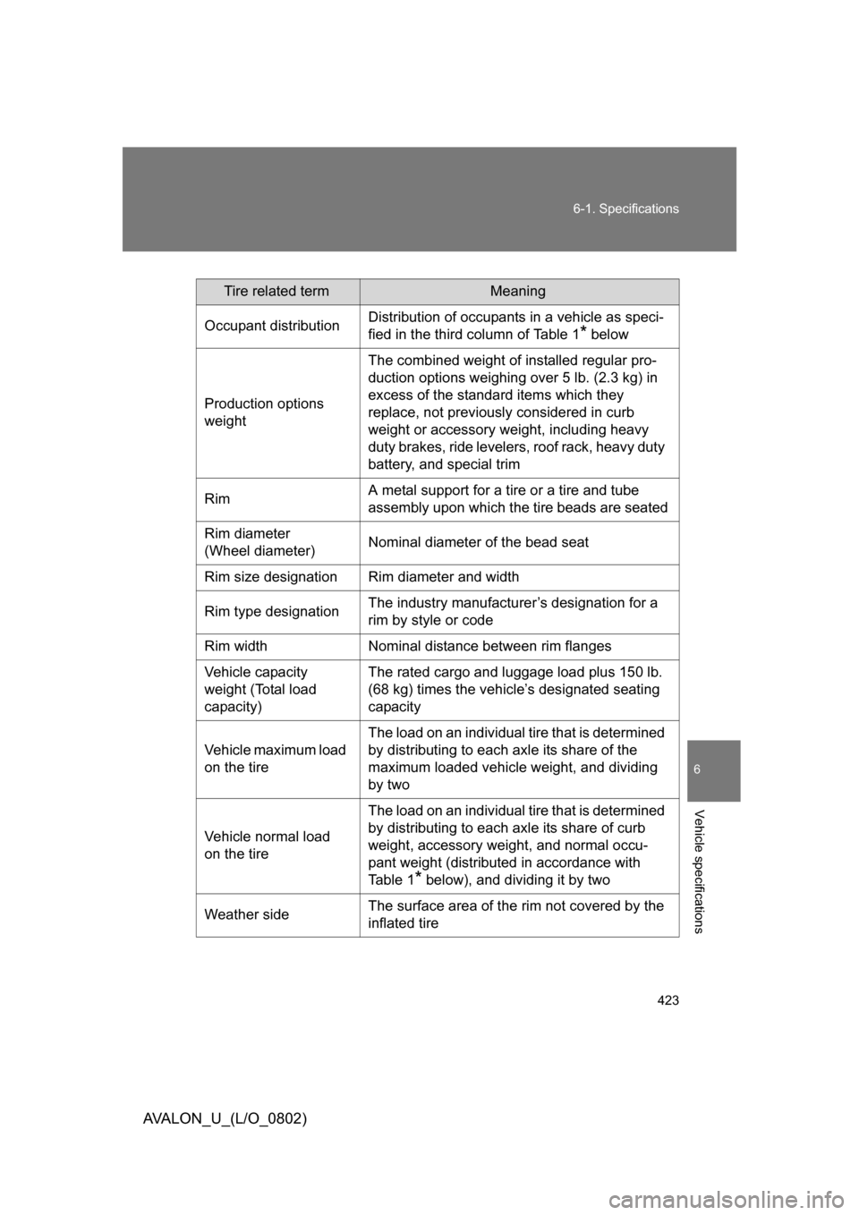
Tire related termMeaning
Occupant distribution Distribution of occupants in a vehicle as speci-
fied in the third column of Table 1
* below
Production options
weight The combined weight of installed regular pro-
duction options weighing over 5 lb. (2.3 kg) in
excess of the standard items which they
replace, not previously considered in curb
weight or accessory weight, including heavy
duty brakes, ride levelers, roof rack, heavy duty
battery, and special trim
Rim A metal support for a tire or a tire and tube
assembly upon which the tire beads are seated
Rim diameter
(Wheel diameter) Nominal diameter of the bead seat
Rim size designation Rim diameter and width
Rim type designation The industry manufacturer’s designation for a
rim by style or code
Rim width Nominal distance between rim flanges
Vehicle capacity
weight (Total load
capacity) The rated cargo and luggage load plus 150 lb.
(68 kg) times the vehicle’s designated seating
capacity
Vehicle maximum load
on the tire The load on an individual tire that is determined
by distributing to each axle its share of the
maximum loaded vehicle weight, and dividing
by two
Vehicle normal load
on the tire The load on an individual tire that is determined
by distributing to each axle its share of curb
weight, accessory weight, and normal occu-
pant weight (distributed in accordance with
Ta b l e 1
* below), and dividing it by two
Weather side The surface area of the rim not covered by the
inflated tire