Page 6 of 496

vi
New vehicle warranty
Your new vehicle is covered by the following Toyota limited
warranties:��New vehicle warranty
� �Emission control systems warranty
� �Others
For further information, please refer to the �Owner’s
Warranty Information Booklet" or �Owner ’s Manual
Supplement".
Your responsibility for maintenance
It is the owner ’s responsibility to make sure that the speci-
fied maintenance is performed. Section 6 gives details of
these maintenance requirements. Also included in Section
6 is general maintenance. For scheduled maintenance in-
formation, please refer to the �Scheduled Maintenance
Guide" or �Owner ’s Manual Supplement".
Important health and safety
information about your Toyota
CAUTION
�WARNING: Engine exhaust, some of its constitu- ents, and a wide variety of automobile compo-
nents contain or emit chemicals known to the
State of California to cause cancer and birth de-
fects and other reproductive harm. In addition,
oils, fuels and fluids contained in vehicles as
well as waste produced by component wear con-
tain or emit chemicals known to the State of
California to cause cancer and birth defects or
other reproductive harm.
�Battery posts, terminals and related accessories contain lead and lead compounds. Wash your
hands after handling. Used engine oil contains
chemicals that have caused cancer in laboratory
animals. Always protect your skin by washing
thoroughly with soap and water.
Page 8 of 496

viii
Installation of a mobiletwo−way radio system
As the installation of a mobile two−way radio system in
your vehicle could affect electronic systems such as fol-
lows, be sure to check with your Toyota dealer for precau-
tionary measures or special instructions regarding installa-
tion.
��Multiport fuel injection system/sequential multiport
fuel injection system
� �SRS airbag system
� �Seat belt pretensioner system
� �Traction control system (two−wheel drive models)
� �Active traction control system
(four−wheel drive models)
� ��AUTO LSD" system (two−wheel drive models)
� �Vehicle stability control system
� �Downhill assist control system
(four−wheel drive models)
� �Hill−start assist control system
� �Rear height control air suspension
��Tire pressure warning system
� �Cruise control system
� �Anti−lock brake system
� �Electronic throttle control system
Tires and loading on your
To y o t a
Underinflated or overinflated tire pressure and the
excess load may result in the deterioration of
steering ability and braking ability, leading to an
accident. Check the tire inflation pressure periodi-
cally and be sure to keep the load limits given in
this Owner ’s Manual. For details about tire inflation
pressure and load limits, see pages 441 and 364.
Page 10 of 496
x
Leak detection pump
This pump performs fuel evaporation leakage check. This
check is done approximately five hours after the engine is
turned off. So you may hear sound coming from under-
neath the luggage compartment for several minutes. It
does not indicate a malfunction.
Perchlorate Material
Special handling may apply,
See www.dtsc.ca.gov/hazardouswaste/perchlorate.
Your vehicle has components that may contain perchlorate.
These components may include airbag, seat belt preten-
sioners, and wireless remote control batteries.
Page 17 of 496
5
15. Engine switch
16. Cruise control switch
17. Hood lock release lever
18. Fuel filler door opener
19. Roll sensing of curtain shield airbags off switch
20. �VSC OFF" switch
21. Center differential lock switch
22. Power outlet main switch
23. Instrument panel light control dial
CY11065
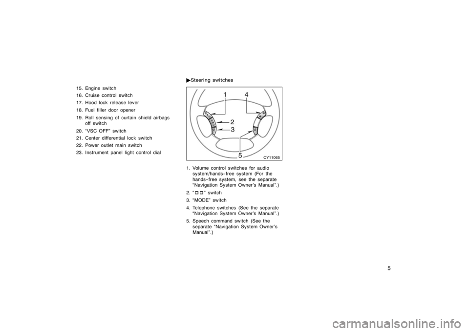
1. Volume control switches for audio system/hands−free system (For the
hands−free system, see the separate
�Navigation System Owner ’s Manual".)
2. � ��" switch
3. �MODE" switch
4. Telephone switches (See the separate �Navigation System Owner ’s Manual".)
5. Speech command switch (See the separate �Navigation System Owner ’s
Manual".)
�
Steering switches
Page 18 of 496
6
CY11062
1. Tachometer
2. Speedometer
3. Service reminder indicators andindicator lights 4. Fuel gauge
5. Low fuel level warning light
6. Engine coolant temperature gauge
7. Trip meter reset knob
8. Odometer and two trip meters
Instrument cluster overview
�
Ty p e A
Page 19 of 496
7
CY11067
1. Service reminder indicators andindicator lights
2. Tachometer 3. Speedometer
4. Fuel gauge
5. Low fuel level warning light6. Engine coolant temperature gauge
7. Trip meter reset knob
8. Odometer and two trip meters
�
Ty p e B
Page 23 of 496

11
OPERATION OF INSTRUMENTS AND
CONTROLS
Keys and Doors
Keys12
. . . . . . . . . . . . . . . . . . . . . . . . . . . . . . . . . . . . .\
. . . . . . . . . . . . . . . . . .
Engine immobilizer system 14
. . . . . . . . . . . . . . . . . . . . . . . . . . . . . . . . . . .
Wireless remote control 15
. . . . . . . . . . . . . . . . . . . . . . . . . . . . . . . . . . . . \
. .
Side doors 22
. . . . . . . . . . . . . . . . . . . . . . . . . . . . . . . . . . . . \
. . . . . . . . . . . . . .
Power windows 27
. . . . . . . . . . . . . . . . . . . . . . . . . . . . . . . . . . . . \
. . . . . . . . . .
Power back window 30
. . . . . . . . . . . . . . . . . . . . . . . . . . . . . . . . . . . . \
. . . . . .
Back door 32
. . . . . . . . . . . . . . . . . . . . . . . . . . . . . . . . . . . . \
. . . . . . . . . . . . . . .
Hood 34
. . . . . . . . . . . . . . . . . . . . . . . . . . . . . . . . . . . . \
. . . . . . . . . . . . . . . . . . .
Theft deterrent system 35
. . . . . . . . . . . . . . . . . . . . . . . . . . . . . . . . . . . . \
. . .
Fuel tank cap 37
. . . . . . . . . . . . . . . . . . . . . . . . . . . . . . . . . . . . \
. . . . . . . . . . .
Electric moon roof 39
. . . . . . . . . . . . . . . . . . . . . . . . . . . . . . . . . . . . \
. . . . . . .
SECTION 1− 2
Page 49 of 496
37
CY12081
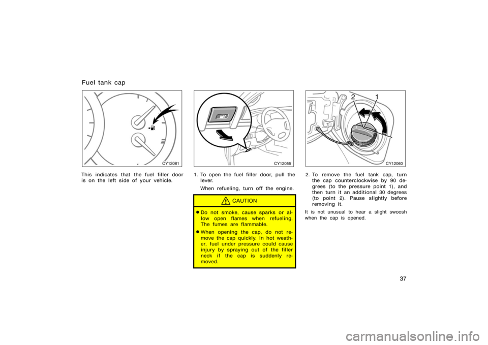
This indicates that the fuel filler door
is on the left side of your vehicle.
CY12055
1. To open the fuel filler door, pull thelever.
When refueling, turn off the engine.
CAUTION
�Do not smoke, cause sparks or al-
low open flames when refueling.
The fumes are flammable.
�When opening the cap, do not re-
move the cap quickly. In hot weath-
er, fuel under pressure could cause
injury by spraying out of the filler
neck if the cap is suddenly re-
moved.
CY12060
2. To remove the fuel tank cap, turnthe cap counterclockwise by 90 de-
grees (to the pressure point 1), and
then turn it an additional 30 degrees
(to point 2). Pause slightly before
removing it.
It is not unusual to hear a slight swoosh
when the cap is opened.
Fuel tank cap