Page 14 of 496
2
1. Side vents
2. Side defroster outlets
3. Instrument cluster
4. Center vents
5. Personal lights
6. Electric moon roof switch
7. Garage door opener
8. Auxiliary boxes
9. Glove box
10. Automatic transmission selector lever
11. Power door lock switches
12. Power window switches
13. Seat heater switches
14. Rear height control air suspension switch
15. Rear vents
16. Trash holder
17. Toyota electronic modulated suspension mode select switch
18. Downhill assist control switch
19. Front cup holders
20. Tilt steering lock release lever
Instrument panel overview
CY11050y
Page 24 of 496

12
CY12049
Your vehicle is supplied with the two
kinds of keys.1. Master keys (black)�These keys work in every lock. Your Toyota dealer will
need one of them to make a new key
with a built−in transponder chip.
2. Sub key (gray)�This key does not work in the glove box.
A transponder chip for engine immobilizer
system has been placed in the head of
the master and sub keys. These chips are
needed to enable the system to function
correctly, so be careful not to lose these
keys. If you make your own duplicate key,
you will not be able to cancel the system
or start the engine. To protect items locked in the glove box
when using valet parking, leave the sub
key with the attendant.
Since the side doors can be locked with-
out a key, you should always carry a
spare key in case you accidentally lock
your keys inside the vehicle.
CY12022
NOTICE
When using a key containing a trans-
ponder chip, observe the following
precautions:
�
When starting the engine, do not
use the key with a key ring resting
on the key grip and do not press
the key ring against the key grip.
Otherwise the engine may not start,
or may stop soon after it starts.
Keys
Page 312 of 496

300
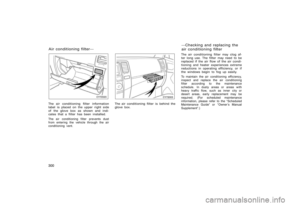
CY72020
The air conditioning filter information
label is placed on the upper right side
of the glove box as shown and indi-
cates that a filter has been installed.
The air conditioning filter prevents dust
from entering the vehicle through the air
conditioning vent.
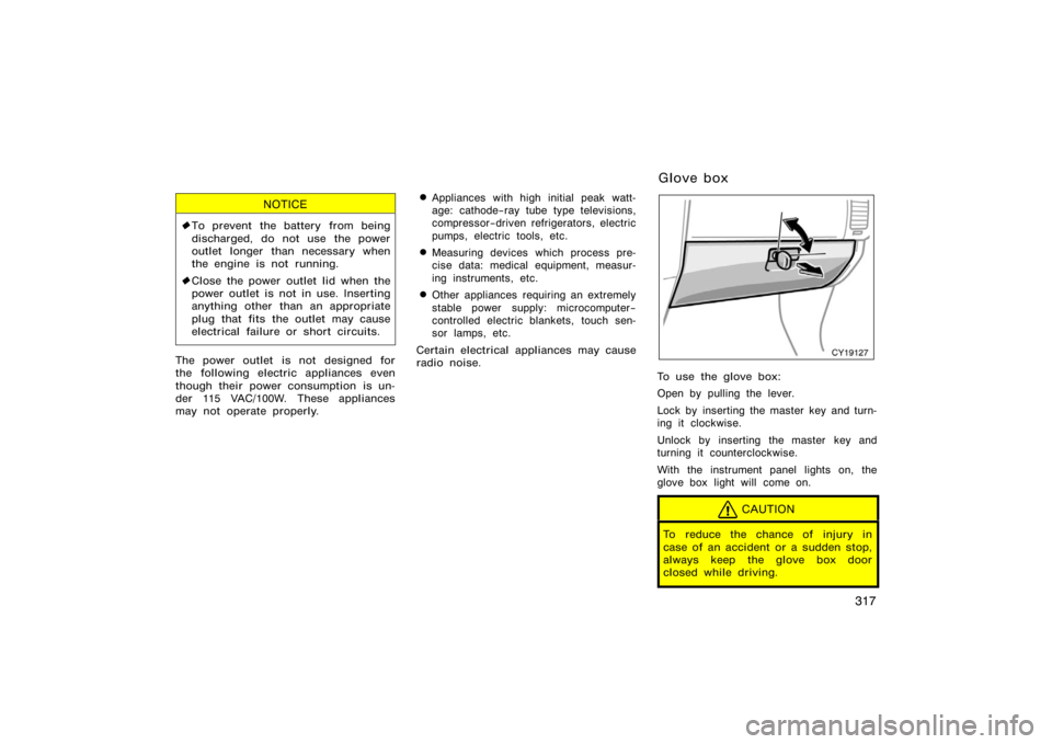
CY72003
The air conditioning filter is behind the
glove box.The air conditioning filter may clog af-
ter long use. The filter may need to be
replaced if the air flow of the air condi-
tioning and heater experiences extreme
reductions in operating efficiency, or if
the windows begin to fog up easily.
To maintain the air conditioning efficiency,
inspect and replace the air conditioning
filter according to the maintenance
schedule. In dusty areas or areas with
heavy traffic flow, such as inner city or
desert areas, early replacement may be
required. (For scheduled maintenance
information, please refer to the �Scheduled
Maintenance Guide" or �Owner ’s Manual
Supplement".)
Air conditioning filter�
�Checking and replacing the
air conditioning filter
Page 313 of 496
301
CY72012
1. Open the glove box. Remove thescrew with a Phillips−head screw-
driver and slide the hook as shown.
CY72004
2. Push in each side of the glove boxto disconnect the claws.
CY72013
3. Remove the filter case by holdingboth sides.
Page 315 of 496

303
OPERATION OF INSTRUMENTS AND
CONTROLS
Other equipment
Multi−information display304
. . . . . . . . . . . . . . . . . . . . . . . . . . . . . . . . . . . .
Compass 307
. . . . . . . . . . . . . . . . . . . . . . . . . . . . . . . . . . . . \
. . . . . . . . . . . . . .
Rear view monitor system 312
. . . . . . . . . . . . . . . . . . . . . . . . . . . . . . . . . . .
Power outlet 315
. . . . . . . . . . . . . . . . . . . . . . . . . . . . . . . . . . . . \
. . . . . . . . . . .
Glove box 317
. . . . . . . . . . . . . . . . . . . . . . . . . . . . . . . . . . . . \
. . . . . . . . . . . . . .
Garage door opener 318
. . . . . . . . . . . . . . . . . . . . . . . . . . . . . . . . . . . . \
. . . .
Auxiliary boxes 322
. . . . . . . . . . . . . . . . . . . . . . . . . . . . . . . . . . . . \
. . . . . . . . .
Rear console box 324
. . . . . . . . . . . . . . . . . . . . . . . . . . . . . . . . . . . . \
. . . . . . .
Tissue box holder 325
. . . . . . . . . . . . . . . . . . . . . . . . . . . . . . . . . . . . \
. . . . . . .
Coin holder 326
. . . . . . . . . . . . . . . . . . . . . . . . . . . . . . . . . . . . \
. . . . . . . . . . . .
Trash holder 326
. . . . . . . . . . . . . . . . . . . . . . . . . . . . . . . . . . . . \
. . . . . . . . . . .
Front cup holders 327
. . . . . . . . . . . . . . . . . . . . . . . . . . . . . . . . . . . . \
. . . . . . .
Rear cup holders and tray 328
. . . . . . . . . . . . . . . . . . . . . . . . . . . . . . . . . . .
Rear cup holders 330
. . . . . . . . . . . . . . . . . . . . . . . . . . . . . . . . . . . . \
. . . . . . .
Bottle holders 330
. . . . . . . . . . . . . . . . . . . . . . . . . . . . . . . . . . . . \
. . . . . . . . . .
Tie−down hooks 331
. . . . . . . . . . . . . . . . . . . . . . . . . . . . . . . . . . . . \
. . . . . . . .
Grocery bag hooks 331
. . . . . . . . . . . . . . . . . . . . . . . . . . . . . . . . . . . . \
. . . . .
Cargo net hooks 332
. . . . . . . . . . . . . . . . . . . . . . . . . . . . . . . . . . . . \
. . . . . . . .
Luggage cover 332
. . . . . . . . . . . . . . . . . . . . . . . . . . . . . . . . . . . . \
. . . . . . . . .
Double deck 333
. . . . . . . . . . . . . . . . . . . . . . . . . . . . . . . . . . . . \
. . . . . . . . . . .
Roof luggage carrier 334
. . . . . . . . . . . . . . . . . . . . . . . . . . . . . . . . . . . . \
. . . .
Floor mat 336
. . . . . . . . . . . . . . . . . . . . . . . . . . . . . . . . . . . . \
. . . . . . . . . . . . . .
SECTION 1− 10
Page 329 of 496

317
NOTICE
�To prevent the battery from being
discharged, do not use the power
outlet longer than necessary when
the engine is not running.
� Close the power outlet lid when the
power outlet is not in use. Inserting
anything other than an appropriate
plug that fits the outlet may cause
electrical failure or short circuits.
The power outlet is not designed for
the following electric appliances even
though their power consumption is un-
der 115 VAC/100W. These appliances
may not operate properly.
�Appliances with high initial peak watt-
age: cathode−ray tube type televisions,
compressor−driven refrigerators, electric
pumps, electric tools, etc.
�Measuring devices which process pre-
cise data: medical equipment, measur-
ing instruments, etc.
�Other appliances requiring an extremely
stable power supply: microcomputer−
controlled electric blankets, touch sen-
sor lamps, etc.
Certain electrical appliances may cause
radio noise.
CY19127
To use the glove box:
Open by pulling the lever.
Lock by inserting the master key and turn-
ing it clockwise.
Unlock by inserting the master key and
turning it counterclockwise.
With the instrument panel lights on, the
glove box light will come on.
CAUTION
To reduce the chance of injury in
case of an accident or a sudden stop,
always keep the glove box door
closed while driving.
Glove box
Page 330 of 496
318
CY19070
On some models, an auxiliary box is
located inside the glove box.
To increase the capacity of the glove box,
raise the lower panel of the auxiliary box.
CY19130
Indicator light
Buttons
The garage door opener (\b
Universal Transceiver) is manufactured
under license from HomeLink\b and can
be programmed to operate garage
doors, gates, entry doors, door locks,
home lighting systems, and security
systems, etc.
Garage door opener
Page 394 of 496

382
CAUTION
�If the total trailer weight exceeds
453 kg (1000 lb.), trailer brakes are
required.
�Never tap into your vehicle’s hy-
draulic system as it would lower its
braking effectiveness .
�Never tow a trailer without using a
safety chain securely attached to
both the trailer and the vehicle. If
damage occurs to the coupling unit
or hitch ball, there is danger of the
trailer wandering over into another
lane.
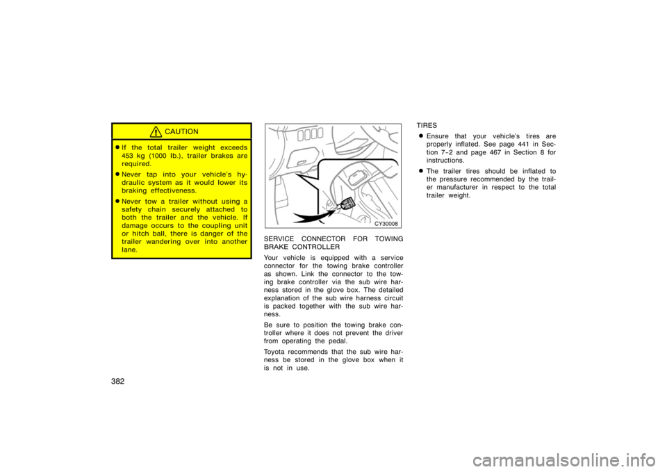
CY30008
SERVICE CONNECTOR FOR TOWING
BRAKE CONTROLLER
Your vehicle is equipped with a service
connector for the towing brake controller
as shown. Link the connector to the tow-
ing brake controller via the sub wire har-
ness stored in the glove box. The detailed
explanation of the sub wire harness circuit
is packed together with the sub wire har-
ness.
Be sure to position the towing brake con-
troller where it does not prevent the driver
from operating the pedal.
Toyota recommends that the sub wire har-
ness be stored in the glove box when it
is not in use. TIRES
�Ensure that your vehicle’s tires are
properly inflated. See page 441 in Sec-
tion 7−2 and page 467 in Section 8 for
instructions.
�The trailer tires should be inflated to
the pressure recommended by the trail-
er manufacturer in respect to the total
trailer weight.