2008 SUZUKI SX4 electronic
[x] Cancel search: electronicPage 91 of 278
4-14
INSTRUMENT PANEL
80J21-03E
For details of the ESP
® systems, refer to
“Electronic Stability Program (ESP
®)” in
the “OPERATING YOUR VEHICLE” sec-
tion.
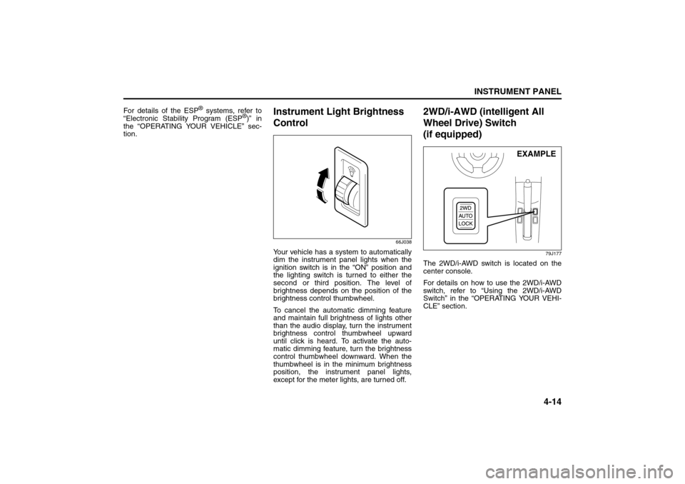
Instrument Light Brightness
Control
66J038
Your vehicle has a system to automatically
dim the instrument panel lights when the
ignition switch is in the “ON” position and
the lighting switch is turned to either the
second or third position. The level of
brightness depends on the position of the
brightness control thumbwheel.
To cancel the automatic dimming feature
and maintain full brightness of lights other
than the audio display, turn the instrument
brightness control thumbwheel upward
until click is heard. To activate the auto-
matic dimming feature, turn the brightness
control thumbwheel downward. When the
thumbwheel is in the minimum brightness
position, the instrument panel lights,
except for the meter lights, are turned off.
2WD/i-AWD (intelligent All
Wheel Drive) Switch
(if equipped)
79J177
The 2WD/i-AWD switch is located on the
center console.
For details on how to use the 2WD/i-AWD
switch, refer to “Using the 2WD/i-AWD
Switch” in the “OPERATING YOUR VEHI-
CLE” section.
EXAMPLE
Information Display:
Glove Box: 3
Page 155 of 278
OPERATING YOUR VEHICLE
6
80J21-03E
60G408
OPERATING YOUR VEHICLEExhaust Gas Warning ......................................................... 6-1
Daily Inspection Checklist .................................................. 6-1
Starting the Engine ............................................................. 6-2
Engine Block Heater (if equipped) ..................................... 6-4
Using the Transaxle ............................................................ 6-5
Using the 2WD/i-AWD (intelligent All Wheel Drive)
Switch (if equipped) ............................................................ 6-7
Braking ................................................................................. 6-9
Electronic Stability Program (ESP®) (if equipped) .......... 6-12
Tire Pressure Monitoring System (TPMS) ........................ 6-14
Break-In ................................................................................ 6-18
Catalytic Converter ............................................................. 6-19
Improving Fuel Economy ................................................... 6-20
Page 158 of 278
6-3OPERATING YOUR VEHICLE
80J21-03E
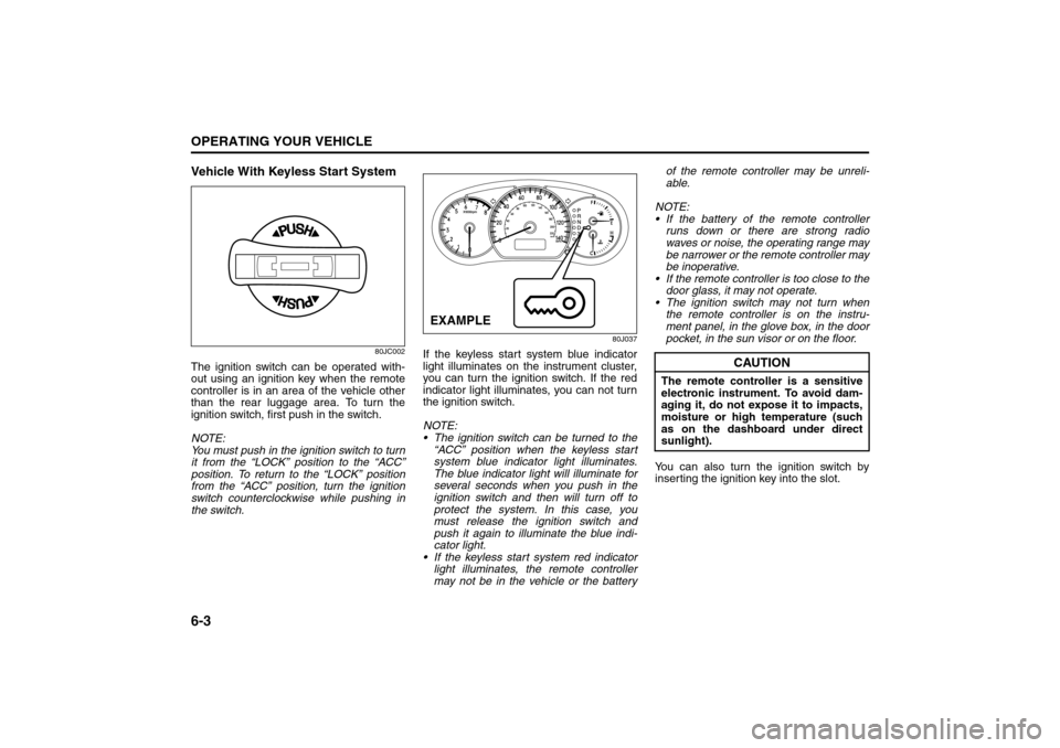
Vehicle With Keyless Start System
80JC002
The ignition switch can be operated with-
out using an ignition key when the remote
controller is in an area of the vehicle other
than the rear luggage area. To turn the
ignition switch, first push in the switch.
NOTE:
You must push in the ignition switch to turn
it from the “LOCK” position to the “ACC”
position. To return to the “LOCK” position
from the “ACC” position, turn the ignition
switch counterclockwise while pushing in
the switch.
80J037
If the keyless start system blue indicator
light illuminates on the instrument cluster,
you can turn the ignition switch. If the red
indicator light illuminates, you can not turn
the ignition switch.
NOTE:
The ignition switch can be turned to the
“ACC” position when the keyless start
system blue indicator light illuminates.
The blue indicator light will illuminate for
several seconds when you push in the
ignition switch and then will turn off to
protect the system. In this case, you
must release the ignition switch and
push it again to illuminate the blue indi-
cator light.
If the keyless start system red indicator
light illuminates, the remote controller
may not be in the vehicle or the batteryof the remote controller may be unreli-
able.
NOTE:
If the battery of the remote controller
runs down or there are strong radio
waves or noise, the operating range may
be narrower or the remote controller may
be inoperative.
If the remote controller is too close to the
door glass, it may not operate.
The ignition switch may not turn when
the remote controller is on the instru-
ment panel, in the glove box, in the door
pocket, in the sun visor or on the floor.
You can also turn the ignition switch by
inserting the ignition key into the slot.EXAMPLE
CAUTION
The remote controller is a sensitive
electronic instrument. To avoid dam-
aging it, do not expose it to impacts,
moisture or high temperature (such
as on the dashboard under direct
sunlight).
Engine Block Heater: 1
Page 162 of 278
6-7OPERATING YOUR VEHICLE
80J21-03E
Using the 2WD/i-AWD
(intelligent All Wheel Drive)
Switch (if equipped)
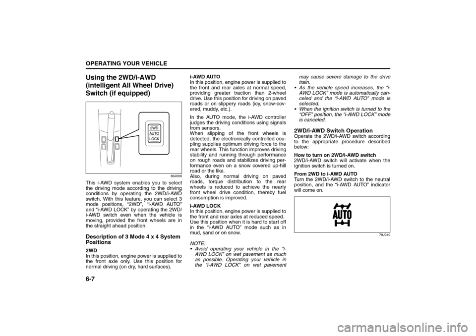
80J009
This i-AWD system enables you to select
the driving mode according to the driving
conditions by operating the 2WD/i-AWD
switch. With this feature, you can select 3
mode positions, “2WD”, “i-AWD AUTO”
and “i-AWD LOCK” by operating the 2WD/
i-AWD switch even when the vehicle is
moving, provided the front wheels are in
the straight ahead position.Description of 3 Mode 4 x 4 System
Positions2WD
In this position, engine power is supplied to
the front axle only. Use this position for
normal driving (on dry, hard surfaces).i-AWD AUTO
In this position, engine power is supplied to
the front and rear axles at normal speed,
providing greater traction than 2-wheel
drive. Use this position for driving on paved
roads or on slippery roads (icy, snow-cov-
ered, muddy, etc.).
In the AUTO mode, the i-AWD controller
judges the driving conditions using signals
from sensors.
When slipping of the front wheels is
detected, the electronically controlled cou-
pling supplies optimum driving force to the
rear wheels. This function improves driving
stability and running through performance
on rough roads and stabilizes driving per-
formance even on a snow covered up-hill
road or the like.
Also, during normal driving on paved
roads, torque distribution to the rear
wheels is reduced to achieve the nearly
front wheel drive condition, thereby fuel
consumption is improved.
i-AWD LOCK
In this position, engine power is supplied to
the front and rear axles at reduced speed.
Use this position when it is hard to start off
in the “i-AWD AUTO” mode such as in
mud, sand or on snow.
NOTE:
Avoid operating your vehicle in the “i-
AWD LOCK” on wet pavement as much
as possible. Operating your vehicle in
the “i-AWD LOCK” on wet pavementmay cause severe damage to the drive
train.
As the vehicle speed increases, the “i-
AWD LOCK” mode is automatically can-
celed and the “i-AWD AUTO” mode is
selected.
When the ignition switch is turned to the
“OFF” position, the “i-AWD LOCK” mode
is canceled.
2WD/i-AWD Switch OperationOperate the 2WD/i-AWD switch according
to the appropriate procedure described
below:
How to turn on 2WD/i-AWD switch
2WD/i-AWD switch will activate when the
ignition switch is turned on.
From 2WD to i-AWD AUTO
Turn the 2WD/i-AWD switch to the neutral
position, and the “i-AWD AUTO” indicator
will come on.
79J040
Braking: 6
Page 167 of 278
6-12
OPERATING YOUR VEHICLE
80J21-03E
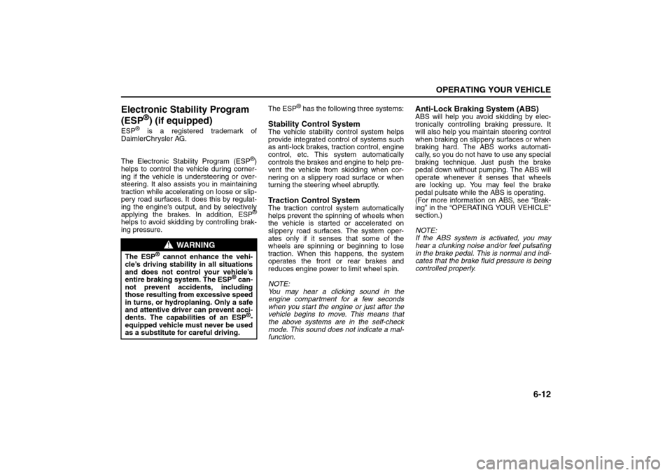
Electronic Stability Program
(ESP
®) (if equipped)
ESP
® is a registered trademark of
DaimlerChrysler AG.
The Electronic Stability Program (ESP
®)
helps to control the vehicle during corner-
ing if the vehicle is understeering or over-
steering. It also assists you in maintaining
traction while accelerating on loose or slip-
pery road surfaces. It does this by regulat-
ing the engine’s output, and by selectively
applying the brakes. In addition, ESP®
helps to avoid skidding by controlling brak-
ing pressure.The ESP
® has the following three systems:
Stability Control SystemThe vehicle stability control system helps
provide integrated control of systems such
as anti-lock brakes, traction control, engine
control, etc. This system automatically
controls the brakes and engine to help pre-
vent the vehicle from skidding when cor-
nering on a slippery road surface or when
turning the steering wheel abruptly.Traction Control SystemThe traction control system automatically
helps prevent the spinning of wheels when
the vehicle is started or accelerated on
slippery road surfaces. The system oper-
ates only if it senses that some of the
wheels are spinning or beginning to lose
traction. When this happens, the system
operates the front or rear brakes and
reduces engine power to limit wheel spin.
NOTE:
You may hear a clicking sound in the
engine compartment for a few seconds
when you start the engine or just after the
vehicle begins to move. This means that
the above systems are in the self-check
mode. This sound does not indicate a mal-
function.
Anti-Lock Braking System (ABS)ABS will help you avoid skidding by elec-
tronically controlling braking pressure. It
will also help you maintain steering control
when braking on slippery surfaces or when
braking hard. The ABS works automati-
cally, so you do not have to use any special
braking technique. Just push the brake
pedal down without pumping. The ABS will
operate whenever it senses that wheels
are locking up. You may feel the brake
pedal pulsate while the ABS is operating.
(For more information on ABS, see “Brak-
ing” in the “OPERATING YOUR VEHICLE”
section.)
NOTE:
If the ABS system is activated, you may
hear a clunking noise and/or feel pulsating
in the brake pedal. This is normal and indi-
cates that the brake fluid pressure is being
controlled properly.
WARNING
The ESP
® cannot enhance the vehi-
cle’s driving stability in all situations
and does not control your vehicle’s
entire braking system. The ESP
® can-
not prevent accidents, including
those resulting from excessive speed
in turns, or hydroplaning. Only a safe
and attentive driver can prevent acci-
dents. The capabilities of an ESP
®-
equipped vehicle must never be used
as a substitute for careful driving.
Page 173 of 278

6-18
OPERATING YOUR VEHICLE
80J21-03E
When the TPMS sensor’s electronic sig-
nal is disturbed in one of the following
ways:
– Electric devices or facilities using simi-
lar radio wave frequencies are nearby.
– A lot of snow or ice covers the vehicle,
in particular, around the wheels or
wheel housings.
– Snow tires or tire chains are used.
When you use non-genuine SUZUKI
wheels or tires.Replacing Tires and/or WheelsIf you get a flat tire, Suzuki recommends
that you have an authorized SUZUKI
dealer mount a new tire on the wheel that
had the flat tire, and reinstall this tire on the
vehicle in place of the spare. The TPMS is
already set up to recognize the ID code of
the original wheel, and normal TPMS oper-
ation will be restored.
If you need to replace original wheels on
your vehicle, your dealer must make sure
that TPMS sensors are installed in the new
wheels and must set up the TPMS to rec-
ognize the new sensors.
NOTE:
A TPMS sensor is not installed in the spare
tire. You should use the spare tire only in
an emergency situation, and should
replace the spare tire as soon as possible
to restore normal TPMS operation.
For Vehicles Sold in U.S.A.This device complies with Part 15 of the
FCC Rules.
Operation is subject to the following two
conditions:
1) This device may not cause harmful
interference.
2) This device must accept any interfer-
ence received, including interference
that may cause undesired operation.
NOTE:
Changes or modifications not expressly
approved by the party responsible for com-
pliance could void the user’s authority to
operate the equipment.Traveling to CANADAPlease note that service for the tire pres-
sure monitoring system may not be avail-
able in CANADA should there be any
problems or malfunctions in the system.
Break-In
WARNING
Only use tires and wheels recom-
mended by SUZUKI as standard or
optional equipment for your vehicle.
Use of tires or wheels not recom-
mended by SUZUKI can result in
TPMS failure. Refer to “Tires” in the
“INSPECTION AND MAINTENANCE”
section for additional information.
CAUTION
The future performance and reliabil-
ity of the engine depends on the care
and restraint exercised during its
early life. It is especially important to
observe the following precautions
during the initial 960 km (600 miles)
of vehicle operation.
After starting, do not race the
engine. Warm it up gradually.
Avoid prolonged vehicle operation
at a constant speed. Moving parts
will break in better if you vary your
speed.
Start off from a stop slowly. Avoid
full throttle starts.
Avoid hard stopping, especially
during the first 320 km (200 miles)
of driving.
Do not drive slowly with the tran-
saxle in a high gear.
Drive the vehicle at moderate
engine speeds.
Page 256 of 278
12-3GENERAL INFORMATION
80J21-03E
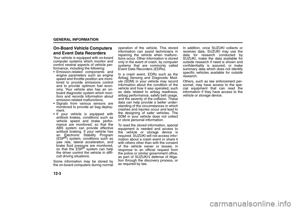
On-Board Vehicle Computers
and Event Data RecordersYour vehicle is equipped with on-board
computer systems which monitor and
control several aspects of vehicle per-
formance, including the following:
Emission-related components and
engine parameters such as engine
speed and throttle position are moni-
tored to provide emissions control
and to provide optimum fuel econ-
omy. Your vehicle also has an on-
board diagnostic system which mon-
itors and records information about
emission-related malfunctions.
Signals from various sensors are
monitored to provide air bag deploy-
ment.
If your vehicle is equipped with
antilock brakes, conditions such as
vehicle speed and brake perfor-
mance are monitored, so that the
ABS system can provide effective
antilock braking. If your vehicle has
an Electronic Stability Program
(ESP
®) system, conditions such as
yaw rate, lateral acceleration, and
brake fluid pressure are monitored,
so that the ESP
® system can help
the driver control the vehicle in diffi-
cult driving situations.
Some information may be stored by
the on-board computers during normaloperation of the vehicle. This stored
information can assist technicians in
repairing the vehicle when malfunc-
tions occur. Other information is stored
only in the event of crash, by computer
systems that are commonly called
Event Data Recorders (EDRs).
In a crash event, EDRs such as the
Airbag Sensing and Diagnostic Mod-
ule (SDM) in your vehicle may record
information about the condition of the
vehicle and how it was operated, such
as data related to airbag readiness,
airbag performance, safety belt usage,
and the severity of the collision. These
data can help provide a better under-
standing of the circumstances in which
crashes and injuries occur and lead to
the designing of safer vehicles. The
SDM in your vehicle does not collect
or store personal information.
To read the stored information, special
equipment is needed and access to
the vehicle or storage device is
required. SUZUKI will not access infor-
mation about a crash event or share it
with others other than with the consent
of the vehicle owner or lessee, in
response to an official request from
the police or similar government office,
as part of SUZUKI’s defense of litiga-
tion through the discovery process, or
as required by law.In addition, once SUZUKI collects or
receives data, SUZUKI may use the
data for research conducted by
SUZUKI, make the data available for
outside research if need is shown and
confidentiality is assured, or make
summary data which does not identify
specific vehicles available for outside
research.
Others, such as law enforcement per-
sonnel, may have access to the spe-
cial equipment that can read the
information if they have access to the
vehicle or storage device.
Reporting Safety Defects: NO
Page 271 of 278
15-1
INDEX
15
80J21-03E
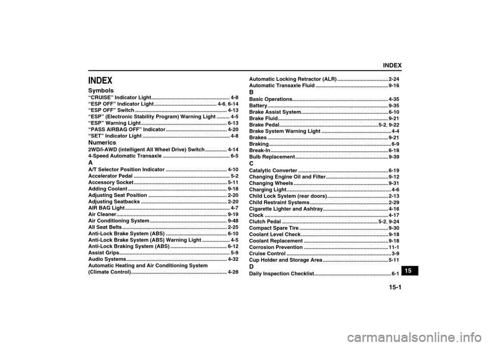
INDEXSymbols“CRUISE” Indicator Light...................................................... 4-8
“ESP OFF” Indicator Light ........................................... 4-6, 6-14
“ESP OFF” Switch ............................................................... 4-13
“ESP” (Electronic Stability Program) Warning Light ......... 4-5
“ESP” Warning Light ........................................................... 6-13
“PASS AIRBAG OFF” Indicator .......................................... 4-20
“SET” Indicator Light ............................................................ 4-8Numerics2WD/i-AWD (intelligent All Wheel Drive) Switch ............... 4-14
4-Speed Automatic Transaxle .............................................. 6-5AA/T Selector Position Indicator .......................................... 4-10
Accelerator Pedal .................................................................. 5-2
Accessory Socket ................................................................ 5-11
Adding Coolant .................................................................... 9-18
Adjusting Seat Position ...................................................... 2-20
Adjusting Seatbacks ........................................................... 2-20
AIR BAG Light ........................................................................ 4-7
Air Cleaner............................................................................ 9-19
Air Conditioning System ..................................................... 9-48
All Seat Belts ........................................................................ 2-25
Anti-Lock Brake System (ABS) .......................................... 6-10
Anti-Lock Brake System (ABS) Warning Light ................... 4-5
Anti-Lock Braking System (ABS) ....................................... 6-12
Assist Grips............................................................................ 5-9
Audio Systems ..................................................................... 4-32
Automatic Heating and Air Conditioning System
(Climate Control).................................................................. 4-28Automatic Locking Retractor (ALR) ................................... 2-24
Automatic Transaxle Fluid .................................................. 9-16
BBasic Operations.................................................................. 4-35
Battery ................................................................................... 9-35
Brake Assist System............................................................ 6-10
Brake Fluid............................................................................ 9-21
Brake Pedal.................................................................... 5-2, 9-22
Brake System Warning Light ................................................ 4-4
Brakes ................................................................................... 9-21
Braking .................................................................................... 6-9
Break-In ................................................................................. 6-18
Bulb Replacement ................................................................ 9-39CCatalytic Converter .............................................................. 6-19
Changing Engine Oil and Filter........................................... 9-12
Changing Wheels ................................................................. 9-31
Charging Light........................................................................ 4-6
Child Lock System (rear doors) .......................................... 2-13
Child Restraint Systems ...................................................... 2-29
Cigarette Lighter and Ashtray............................................. 4-16
Clock ..................................................................................... 4-17
Clutch Pedal .................................................................. 5-2, 9-24
Compact Spare Tire ............................................................. 9-30
Coolant Level Check ............................................................ 9-18
Coolant Replacement .......................................................... 9-18
Corrosion Prevention .......................................................... 11-1
Cruise Control ........................................................................ 3-9
Cup Holder and Storage Area ............................................. 5-11DDaily Inspection Checklist..................................................... 6-1