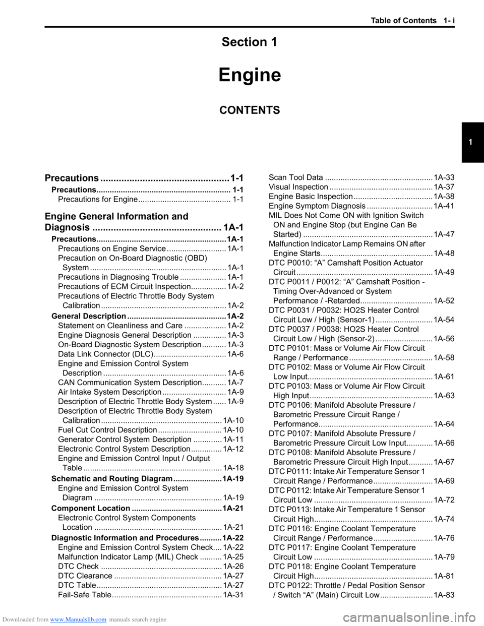
2008 SUZUKI SWIFT fuel indicator schematic
[x] Cancel search: fuel indicator schematicPage 45 of 1496

Downloaded from www.Manualslib.com manuals search engine Table of Contents 1- i
1
Section 1
CONTENTS
Engine
Precautions ................................................. 1-1
Precautions............................................................. 1-1
Precautions for Engine .......................................... 1-1
Engine General Information and
Diagnosis ............. .................................... 1A-1
Precautions........................................................... 1A-1
Precautions on Engine Service ........................... 1A-1
Precaution on On-Board Diagnostic (OBD) System .............................................................. 1A-1
Precautions in Diagnosing Trouble ..................... 1A-1
Precautions of ECM Circuit Inspection................ 1A-2
Precautions of Electric Throttle Body System
Calibration ......................................................... 1A-2
General Description ............................................. 1A-2 Statement on Cleanliness and Care ................... 1A-2
Engine Diagnosis General Description ............... 1A-3
On-Board Diagnostic System Description ........... 1A-3
Data Link Connector (DLC) ................................. 1A-6
Engine and Emission Control System Description ........................................................ 1A-6
CAN Communication System Description........... 1A-7
Air Intake System Description ............................. 1A-9
Description of Electric Throttle Body System ...... 1A-9
Description of Electric Throttle Body System Calibration ....................................................... 1A-10
Fuel Cut Control Description ............................. 1A-10
Generator Control System Description ............. 1A-11
Electronic Control System Description .............. 1A-12
Engine and Emission Control Input / Output Table ............................................................... 1A-18
Schematic and Routing Diagram ...................... 1A-19 Engine and Emission Control System Diagram .......................................................... 1A-19
Component Locatio n ......................................... 1A-21
Electronic Control System Components Location .......................................................... 1A-21
Diagnostic Information and Procedures .......... 1A-22 Engine and Emission Control System Check.... 1A-22
Malfunction Indicator Lamp (MIL) Check .......... 1A-25
DTC Check ....................................................... 1A-26
DTC Clearance ................................................. 1A-27
DTC Table ......................................................... 1A-27
Fail-Safe Table ................ .................................. 1A-31 Scan Tool Data ................................................. 1A-33
Visual Inspection ............................................... 1A-37
Engine Basic Inspection .................................... 1A-38
Engine Symptom Diagnosis .............................. 1A-41
MIL Does Not Come ON with Ignition Switch
ON and Engine Stop (but Engine Can Be
Started) ........................................................... 1A-47
Malfunction Indicator Lamp Remains ON after Engine Starts................................................... 1A-48
DTC P0010: “A” Camshaft Position Actuator Circuit .............................................................. 1A-49
DTC P0011 / P0012: “A” Camshaft Position - Timing Over-Advanced or System
Performance / -Retarded................................. 1A-52
DTC P0031 / P0032: HO2S Heater Control Circuit Low / High (Sensor-1) .......................... 1A-54
DTC P0037 / P0038: HO2S Heater Control Circuit Low / High (Sensor-2) .......................... 1A-56
DTC P0101: Mass or Volume Air Flow Circuit Range / Performance ...................................... 1A-58
DTC P0102: Mass or Volume Air Flow Circuit Low Input......................................................... 1A-61
DTC P0103: Mass or Volume Air Flow Circuit High Input ........................................................ 1A-63
DTC P0106: Manifold Absolute Pressure /
Barometric Pressure Circuit Range /
Performance.................................................... 1A-64
DTC P0107: Manifold Absolute Pressure /
Barometric Pressure Circ uit Low Input............ 1A-66
DTC P0108: Manifold Absolute Pressure /
Barometric Pressure Circ uit High Input ........... 1A-67
DTC P0111: Intake Air Temperature Sensor 1 Circuit Range / Performance ........................... 1A-69
DTC P0112: Intake Air Temperature Sensor 1 Circuit Low ...................................................... 1A-72
DTC P0113: Intake Air Temperature 1 Sensor Circuit High...................................................... 1A-74
DTC P0116: Engine Coolant Temperature Circuit Range / Performance ........................... 1A-76
DTC P0117: Engine Coolant Temperature Circuit Low ...................................................... 1A-79
DTC P0118: Engine Coolant Temperature Circuit High...................................................... 1A-81
DTC P0122: Throttle / Pedal Position Sensor / Switch “A” (Main) Circuit Low ........................ 1A-83
Page 1168 of 1496

Downloaded from www.Manualslib.com manuals search engine 9-ii Table of Contents
List of Connectors ........................................... 9A-103
C Connector .................................................... 9A-103
D Connector (M16A engine) ........................... 9A-104
E Connector .................................................... 9A-104
G Connector .................................................... 9A-106
J Connector ..................................................... 9A-108
K Connector .................................................... 9A-109
L Connector..................................................... 9A-109
M Connector (SPORT model) ......................... 9A-111
O Connector .................................................... 9A-111
R Connector .................................................... 9A-111
Lighting Systems .................................... 9B-1
Component Location ........... ................................9B-1
Lighting System Component s Location............... 9B-1
Interior Light System Location............................. 9B-2
Diagnostic Information and Procedures ............ 9B-2 Headlight Symptom Diagnosis ............................ 9B-2
Headlight Leveling System Symptom Diagnosis (If Equipped) ..................................... 9B-2
Turn Signal and Hazard Warning Light Symptom Diagnosis .......................................... 9B-3
Clearance, Tail and License Plate Light Symptom Diagnosis .......................................... 9B-3
Back-Up Light Symptom Diagnosis..................... 9B-4
Brake Light Symptom Diagnosis ......................... 9B-4
Front Fog Light Symptom Diagnosis (If Equipped) .......................................................... 9B-4
Interior Light Symptom Diagnosis ....................... 9B-5
Repair Instructions ..............................................9B-5 Headlight Housing Removal and Installation ...... 9B-5
Headlight Bulb Replacemen t............................... 9B-6
Headlight Aiming Adjustment with Screen .......... 9B-6
Headlight Switch (in Lighting Switch) Removal and Installation ................................... 9B-8
Headlight Switch (in Lighting Switch) Inspection .......................................................... 9B-8
Hazard Warning Switch Removal and Installation ......................................................... 9B-8
Hazard Warning Switch Inspection ..................... 9B-9
Brake Light Switch Inspection ............................. 9B-9
Turn Signal Light Switch (in Lighting Switch) Removal and Installation ................................... 9B-9
Turn Signal Light Switch (in Lighting Switch) Inspection .......................................................... 9B-9
Turn Signal and Hazard Warning Relay Removal and Installation ................................... 9B-9
Turn Signal and Hazard Warning Relay Inspection ........................................................ 9B-10
License Light Removal and Installation............. 9B-10
Front Fog Light Removal and Installation (If Equipped) ........................................................ 9B-11
Front Fog Light Bulb Replacement (If Equipped) ........................................................ 9B-11
Front Fog Light Switch Inspection (If Equipped) ........................................................ 9B-11
Front Fog Light Relay Inspection (If Equipped) ........................................................ 9B-11
Front Fog Light Aiming Adjustment with Screen (If Equipped) ....................................... 9B-12 Headlight Leveling Switch Inspection (If
Equipped) ........................................................ 9B-13
Headlight Leveling Actuator Inspection (If Equipped) ........................................................ 9B-13
Instrumentation / Driver Info. / Horn ...... 9C-1
Precautions ...........................................................9C-1 Precautions in Diagnosing Troubles for Combination Meter ............................................9C-1
General Description .............................................9C-1 CAN Communication System Description...........9C-1
Auto Volume Co ntrol System Description (If
Equipped) ..........................................................9C-3
Schematic and Routing Diagram ........................9C-4 Combination Meter Circuit Diagram ....................9C-4
Component Location ............ ...............................9C-6
Audio System Component Location ....................9C-6
Diagnostic Information and Procedures ............9C-6 Speedometer and VSS Symp tom Diagnosis ......9C-6
Tachometer Symptom Diagnosis ........................9C-6
Engine Coolant Temperature (ECT) Meter Symptom Diagnosis ..........................................9C-7
Fuel Meter Symptom Diagnosis ..........................9C-7
Low Fuel Warning Light Symptom Diagnosis .....9C-7
Oil Pressure Warning Light Symptom Diagnosis ..........................................................9C-8
Brake and Parking Brake Warning Light Symptom Diagnosis ..........................................9C-8
Seat Belt Reminder Light Symptom Diagnosis (If Equipped)......................................................9C-8
A/T Shift Position Indicator Symptom Diagnosis (A/T Model).......................................9C-9
Charge Warning Light Sy mptom Diagnosis ........9C-9
Main Beam (High Beam) Indicator Symptom Diagnosis ..........................................................9C-9
Warning Buzzer Circuit Sy mptom Diagnosis ....9C-10
Cigarette Lighter Symptom Diagnosis (If Equipped) ........................................................9C-10
Horn Symptom Diagnosis .................................9C-10
Information Display Symptom Diagnosis (If Equipped) ........................................................9C-11
Clock Symptom Diagnosis (If Equipped)...........9C-12
Audio System Symptom Diagnosis (If Equipped) ........................................................9C-12
Remote Audio Control Switch Symptom Diagnosis (If Equipped) ...................................9C-13
Navigation Symptom Diagnosis (If Equipped)...9C-14
Repair Instructions ............ ................................9C-14
Ignition Switch Removal and Installation...........9C-14
Ignition Switch Inspection..................................9C-14
Combination Meter Removal and Installation ...9C-15
Fuel Level Sensor Removal and Installation .....9C-15
Fuel Level Sensor Inspection ............................9C-15
Oil Pressure Switch Remova l and Installation ..9C-15
Oil Pressure Switch Inspec tion .........................9C-16
Engine Coolant Temperature (ECT) Sensor Inspection ........................................................9C-16
Brake Fluid Level Switch Inspection .................9C-16
Parking Brake Switch Inspec tion.......................9C-16
Page 1299 of 1496

Downloaded from www.Manualslib.com manuals search engine Instrumentation / Driver Info. / Horn: 9C-4
Schematic and Routing Diagram
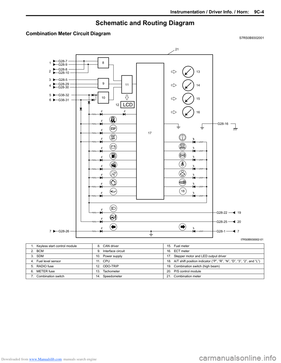
Combination Meter Circuit DiagramS7RS0B9302001
16
15
14
13
G28-5
5
6
3
G28-26
7
G28-2219
G28-2520
G28-17
12
10 11
21
9
17
G28-304G28-29
18
G28-16
G28-9
G28-10G28-8 G28-7
1
2 8
G38-31
G38-32
I7RS0B930002-01
1. Keyless start control module
8. CAN driver 15. Fuel meter
2. BCM 9. Interface circuit 16. ECT meter
3. SDM 10. Power supply 17. Stepper motor and LED output driver
4. Fuel level sensor 11. CPU 18. A/T shift position indicator (“P”, “R”, “N”, “D”, “3”, “2”, and “L”)
5. RADIO fuse 12. ODO-TRIP 19. Combination switch (high beam)
6. METER fuse 13. Tachometer 20. P/S control module
7. Combination switch 14. Speedometer 21. Combination meter