2008 SUZUKI SWIFT crankshaft mounting
[x] Cancel search: crankshaft mountingPage 47 of 1496

Downloaded from www.Manualslib.com manuals search engine Table of Contents 1-iii
EVAP Canister Purge Valve and Its Circuit
Inspection.......................................................... 1B-2
Vacuum Passage Inspection .............................. 1B-3
Vacuum Hose and Purge Valve Chamber Inspection.......................................................... 1B-3
EVAP Canister Purge Valve Inspection .............. 1B-3
EVAP Canister Inspection ... ................................ 1B-4
EGR Valve Removal and Installation .................. 1B-4
EGR Valve Inspection ......................................... 1B-4
PCV Hose Inspection .......................................... 1B-4
PCV Valve Inspection ......................................... 1B-5
Special Tools and Equipmen t ............................. 1B-5
Special Tool ........................................................ 1B-5
Engine Electrical Devices .. ..................... 1C-1
Repair Instructions .............................................. 1C-1
ECM Removal and Installation ............................ 1C-1
MAP Sensor Inspection ...................................... 1C-2
Electric Throttle Body Assembly On-Vehicle
Inspection.......................................................... 1C-2
Electric Throttle Body System Calibration ........... 1C-5
APP Sensor Assembly On-V ehicle Inspection .... 1C-5
APP Sensor Assembly Removal and Installation ......................................................... 1C-5
APP Sensor Assembly Inspection ...................... 1C-6
ECT Sensor Removal and In stallation ................ 1C-6
ECT Sensor Inspection ....................................... 1C-7
HO2S-1 and HO2S-2 Heater On-Vehicle Inspection.......................................................... 1C-7
HO2S-1 and HO2S-2 Removal and Installation ......................................................... 1C-7
CMP Sensor Removal and In stallation ............... 1C-8
Camshaft Position (CMP) Se nsor Inspection ...... 1C-8
CKP Sensor Removal and Installation ................ 1C-9
CKP Sensor Inspection ....................................... 1C-9
Knock Sensor Removal and Installation ........... 1C-10
Main Relay, Fuel Pump Relay and Starting
Motor Control Relay Inspection....................... 1C-10
MAF and IAT Sensor On-Vehicle Inspection .... 1C-11
MAF and IAT Sensor Removal and Installation ....................................................... 1C-11
MAF and IAT Sensor Inspection ....................... 1C-12
Electric Load Current Sensor On-Vehicle Inspection........................................................ 1C-12
Specifications ..................................................... 1C-13
Tightening Torque Specifications ...................... 1C-13
Engine Mechanical ......... ......................... 1D-1
General Description ............................................. 1D-1
Engine Construction Description ......................... 1D-1
Camshaft Position Control (VVT Variable Valve Timing) System Description .................... 1D-2
Diagnostic Information and Procedures ............ 1D-4 Compression Check ............................................ 1D-4
Engine Vacuum Check ....................................... 1D-5
Valve Lash (Clearance) Inspection ..................... 1D-6
Repair Instructions .............................................. 1D-9 Air Cleaner Components ..................................... 1D-9
Air Cleaner Element Removal and Installation .... 1D-9 Air Cleaner Element Ins
pection and Cleaning ..1D-10
Cylinder Head Co ver Removal and
Installation .......................................................1D-10
Throttle Body and Intake Manifold
Components ....................................................1D-12
Throttle Body On-Vehicle Inspection.................1D-13
Electric Throttle Body Assembly Removal and Installation .......................................................1D-13
Throttle Body Cleaning......................................1D-14
Intake Manifold Removal and Installation .........1D-14
Engine Mountings Components ........................1D-16
Engine Assembly Removal and Installation ......1D-17
Timing Chain Cover Components .....................1D-20
Timing Chain Cover Removal and Installation ..1D-21
Timing Chain Cover Inspection .........................1D-23
Oil Control Valve Removal and Installation .......1D-23
Oil Control Valve Inspection ..............................1D-24
Timing Chain and Chain Tensioner Components ....................................................1D-24
Timing Chain and Chain Tensioner Removal and Installation ................................................1D-25
Timing Chain and Chain Tensioner Inspection ..1D-27
Camshaft, Tappet and Shim Components ........1D-28
Camshaft, Tappet and Shim Removal and Installation .......................................................1D-29
Camshaft, Tappet and Shim Inspection ............1D-31
Valves and Cylinder Head Components ...........1D-34
Valves and Cylinder Head Removal and
Installation .......................................................1D-35
Valves and Cylinder Head Disassembly and Assembly.........................................................1D-37
Valves and Valve Guides Inspection.................1D-40
Cylinder Head Inspection . .................................1D-42
Valve Spring Inspection ....................................1D-43
Pistons, Piston Rings , Connecting Rods and
Cylinders Components ....................................1D-44
Pistons, Piston Rings , Connecting Rods and
Cylinders Removal and Installation .................1D-45
Pistons, Piston Rings , Connecting Rods and
Cylinders Disassembly and Assembly ............1D-46
Cylinders, Pistons and Piston Rings Inspection ........................................................1D-47
Piston Pins and Connecting Rods Inspection ...1D-49
Crank Pin and Connecting Rod Bearings Inspection ........................................................1D-50
Main Bearings, Cran kshaft and Cylinder
Block Components ..........................................1D-53
Main Bearings, Cran kshaft and Cylinder
Block Removal and Installa tion .......................1D-54
Crankshaft Inspection .......................................1D-57
Main Bearings Inspection . .................................1D-59
Sensor Plate Inspection ....................................1D-63
Rear Oil Seal Inspection ...................................1D-63
Flywheel Inspection...........................................1D-63
Cylinder Block Inspection ..................................1D-63
Specifications .................... .................................1D-64
Tightening Torque Specifications ......................1D-64
Special Tools and Equipmen t ...........................1D-66
Recommended Service Material .......................1D-66
Special Tool ......................................................1D-66
Page 305 of 1496

Downloaded from www.Manualslib.com manuals search engine Engine Mechanical: 1D-20
15) Install A/C compressor to its bracket (if equipped) referring to “Compressor Assembly Removal and
Installation in Section 7B” or “Compressor Assembly
Removal and Installa tion in Section 7B”.
16) Adjust A/C compressor belt tension (if equipped) referring to “Compressor Drive Belt Inspection and
Adjustment in Section 7B” or “Compressor Drive Belt
Inspection and Adjustment in Section 7B”.
17) Check to ensure that a ll removed parts are back in
place.
Reinstall any necessary parts which have not been
reinstalled.
18) Refill cooling system with coolant referring to “Cooling System Flush and Refill in Section 1F”. 19) Refill engine with engine oil
referring to “Engine Oil
and Filter Change in Section 0B”.
20) Refill transaxle with transa xle oil referring to“Manual
Transaxle Oil Change in Section 5B” or “A/T Fluid
Change in Section 5A”.
21) Install battery and tray.
22) Connect positive and negative cable at battery.
23) Install engine hood and connect windshield washer hose.
24) Verify that there is no fu el leakage, coolant leakage,
oil leakage and exhaust gas leakage at each
connection.
Timing Chain Cover ComponentsS7RS0B1406012
I6RS0C140015-02
1. Crankshaft pulley bolt 13. Oil gallery pipe No.2 bolt
2. Crankshaft pulley 14. Oil gallery pipe No.3
3. Oil seal : Apply engine oil to oil seal lip. 15. Oil gallery pipe No.3 bolt
4. Timing chain cover : Apply sealant 99000-31140 to the mating surface of cylinder and cylinder head.
: Apply sealant 99000-31260 to the mating surface of timing chain cover referring to the
figure of Step 4) of “Installation” under “Timing Chain Cover Removal and Installation”. 16. O-ring
: Apply engine oil.
5. Pin 17. Oil control valve
6. Cap bolt 18. Oil control valve mounting nut
7. Timing chain cover mounting bolts 19. Cap
8. Timing chain cover mounting nut : 11 N ⋅m (1.1 kgf-m, 8.0 lb-ft)
9. Oil gallery pipe No.1 :25 N⋅m (2.5 kgf-m, 18.0 lb-ft)
Page 308 of 1496

Downloaded from www.Manualslib.com manuals search engine 1D-23 Engine Mechanical:
8) Install new O-ring (1) to oil gallery pipes No.2 (2) and
No.3 (3).
9) Install oil gallery pipes No.2 and No.3 to cylinder
head (4) and timing chain cover (5).
Tighten bolts to specified torque.
Tightening torque
Oil gallery pipe No.2 and No.3 bolt (a): 11 N·m (
1.1 kgf-m, 8.0 lb-ft)
10) Install water pump pulley. 11) Install cylinder head cover referring to “Cylinder Head Cover Removal and Installation”.
12) Install oil pan referring to “Oil Pan and Oil Pump
Strainer Removal and Installation in Section 1E”.
13) Install crankshaft pulley (1). Tighten bolt (2) to specified torque. To lock crankshaft pulley, use
special tool with it as shown in figure.
Special tool
(A): 09917–68221
Tightening torque
Crankshaft pulley bolt (a): 150 N·m (15.0 kgf-m,
108.5 lb-ft)
14) Install engine assembly to vehicle referring to “Engine Assembly Removal and Installation”.
Timing Chain Cover InspectionS7RS0B1406014
Oil Seal
Check oil seal lip for fault or other damage. Replace as
necessary. Timing Chain Cover
Inspect strainer (1) of oil passage for driving intake cam
timing sprocket assembly (VVT actuator).
If clog or foreign matter exists, clean strainer.
Oil Control Valve Removal and InstallationS7RS0B1406015
Removal
Remove oil gallery pipe No.1
(1) and oil control valve (2)
from timing chain cover (3).
Installation
1) Install new O-ring (4) to oil control valve.
2) Install oil control valve to timing chain cover. Tighten nuts to specification.
Tightening torque
Oil control valve mounting nut (a): 11 N·m (1.1
kgf-m, 8.0 lb-ft)
3) Install oil gallery pipe No .1 with new copper washers
(5) to timing chain cover.
Tighten bolts to specification.
Tightening torque
Oil gallery pipe No.1 bolt (b): 30 N·m (3.0 kgf-m,
21.5 lb-ft)
(a)
(a) 1
2
3
4
5
I3RH0B140027-01
I2RH0B140056-01
1
I3RH0B140028-01
1
5
(b) 3
(a)
2 4
5
I3RM0A140027-01
Page 309 of 1496

Downloaded from www.Manualslib.com manuals search engine Engine Mechanical: 1D-24
Oil Control Valve InspectionS7RS0B1406016
Oil Control Valve1) Inspect strainer (1) and mating surface (2) of oil control valve for clog or damage. Clean oil control
valve if clog or foreign matter is present on strainer
or mating surface of oil control valve.
Replace oil control valve if its mating surface is
damaged.
2) Check resistance between terminals of oil control
valve.
Oil control valve resistance
6.7 – 7.7 Ω (at 20 °C (68 °F)) Oil Gallery Pipe
Inspect oil gallery pipes No
.1, No.2 (2) and No.3 (3).
Replace if crack, deformation or clog exists.
Timing Chain and Chain Tensioner ComponentsS7RS0B1406017
1
2
I3RM0A140028-01
1
3
2
I3RH0B140030-01
I4RS0A140012-04
1. Crankshaft timing sprocket 5. Timing chain tensioner adjuster assembly 9. Spacer
2. Timing chain : Apply engine oil. 6. Chain tensioner adjuster mounting bolt
: 25 N⋅m (2.5 kgf-m, 18.0 lb-ft)
3. Timing chain No.1 guide : Apply engine oil to sliding surface. 7. Timing chain tensioner bolt
: 11 N⋅m (1.1 kgf-m, 8.0 lb-ft)
4. Timing chain tensioner : Apply engine oil to sliding surface. 8. Timing chain No.1 guide bolt
: 9 N⋅m (0.9 kgf-m, 6.5 lb-ft)
Page 335 of 1496

Downloaded from www.Manualslib.com manuals search engine Engine Mechanical: 1D-50
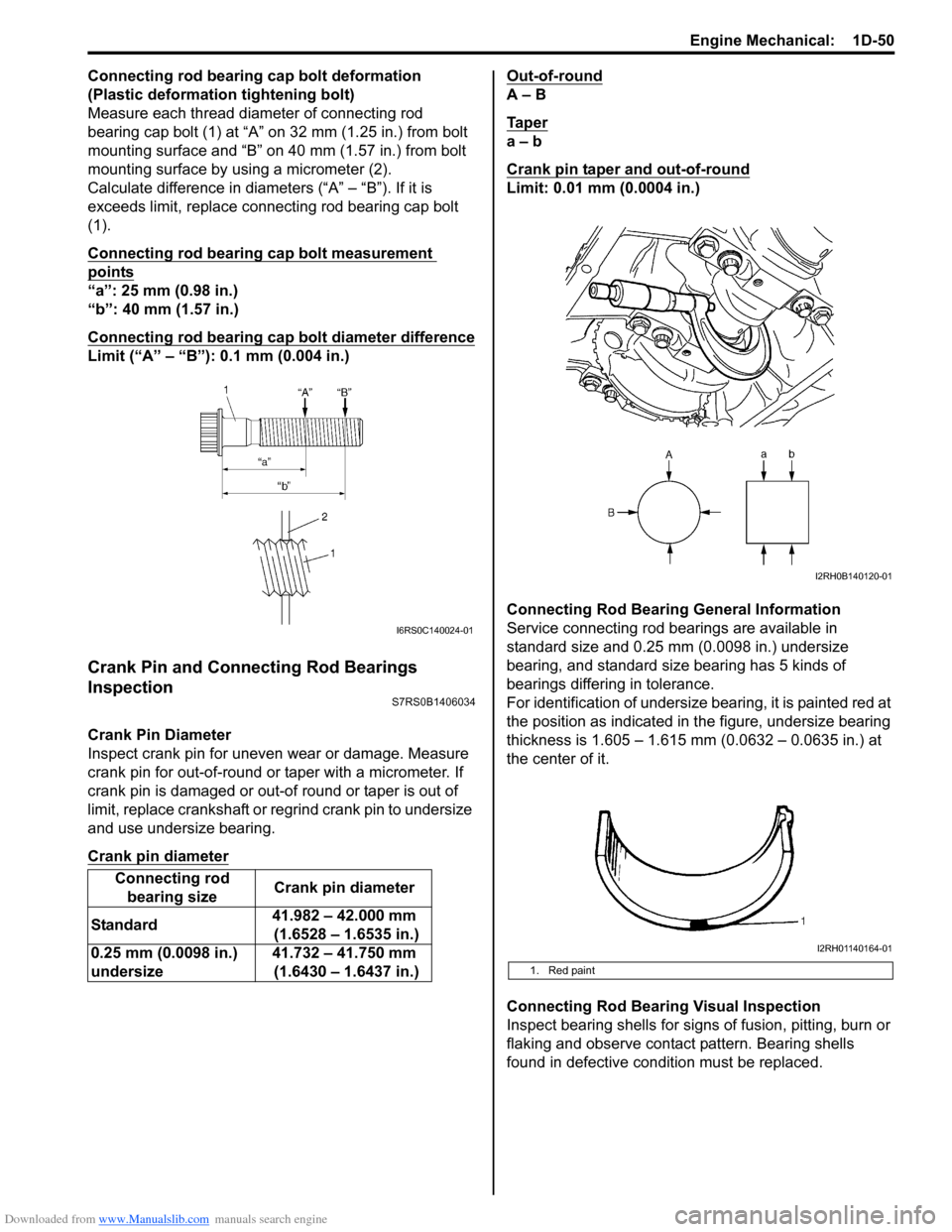
Connecting rod bearing cap bolt deformation
(Plastic deformation tightening bolt)
Measure each thread diameter of connecting rod
bearing cap bolt (1) at “A” on 32 mm (1.25 in.) from bolt
mounting surface and “B” on 40 mm (1.57 in.) from bolt
mounting surface by using a micrometer (2).
Calculate difference in diameters (“A” – “B”). If it is
exceeds limit, replace connecting rod bearing cap bolt
(1).
Connecting rod bearing cap bolt measurement
points
“a”: 25 mm (0.98 in.)
“b”: 40 mm (1.57 in.)
Connecting rod bearing cap bolt diameter difference
Limit (“A” – “B”): 0.1 mm (0.004 in.)
Crank Pin and Connecting Rod Bearings
Inspection
S7RS0B1406034
Crank Pin Diameter
Inspect crank pin for uneven wear or damage. Measure
crank pin for out-of-round or taper with a micrometer. If
crank pin is damaged or out-of round or taper is out of
limit, replace crankshaft or regrind crank pin to undersize
and use undersize bearing.
Crank pin diameter
Out-of-round
A – B
Ta p e r
a – b
Crank pin taper and out-of-round
Limit: 0.01 mm (0.0004 in.)
Connecting Rod Bearing General Information
Service connecting rod be arings are available in
standard size and 0.25 mm (0.0098 in.) undersize
bearing, and standard size bearing has 5 kinds of
bearings differing in tolerance.
For identification of undersize bearing, it is painted red at
the position as indicated in the figure, undersize bearing
thickness is 1.605 – 1.615 mm (0.0632 – 0.0635 in.) at
the center of it.
Connecting Rod Bearing Visual Inspection
Inspect bearing shells for signs of fusion, pitting, burn or
flaking and observe contact pattern. Bearing shells
found in defective condition must be replaced.
Connecting rod
bearing size Crank pin diameter
Standard 41.982 – 42.000 mm
(1.6528 – 1.6535 in.)
0.25 mm (0.0098 in.)
undersize 41.732 – 41.750 mm
(1.6430 – 1.6437 in.)
I6RS0C140024-01
1. Red paint
I2RH0B140120-01
I2RH01140164-01
Page 338 of 1496

Downloaded from www.Manualslib.com manuals search engine 1D-53 Engine Mechanical:
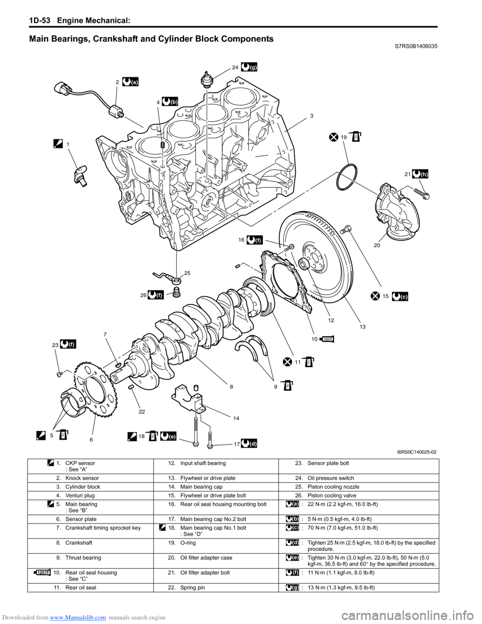
Main Bearings, Crankshaft and Cylinder Block ComponentsS7RS0B1406035
(a)
(c)
(d)(e)
(b)
(f)
(f)
(f)
(g)
(h)
12
3
4
5 67
8910
11 15
12 13
14 16
17
18 19
2021
22
23 24
25
26
OIL
OIL
OIL
OILOIL
I6RS0C140025-02
1. CKP sensor : See “A” 12. Input shaft bearing 23. Sensor plate bolt
2. Knock sensor 13. Flywheel or drive plate 24. Oil pressure switch 3. Cylinder block 14. Main bearing cap 25. Piston cooling nozzle
4. Venturi plug 15. Flywheel or drive plate bolt 26. Piston cooling valve
5. Main bearing : See “B” 16. Rear oil seal housing mounting bolt : 22 N
⋅m (2.2 kgf-m, 16.0 lb-ft)
6. Sensor plate 17. Main bearing cap No.2 bolt : 5 N ⋅m (0.5 kgf-m, 4.0 lb-ft)
7. Crankshaft timing sprocket key 18. Main bearing cap No.1 bolt : See “D”:70 N
⋅m (7.0 kgf-m, 51.0 lb-ft)
8. Crankshaft 19. O-ring : Tighten 25 N ⋅m (2.5 kgf-m, 18.0 lb-ft) by the specified
procedure.
9. Thrust bearing 20. Oil filter adapter case : Tighten 30 N ⋅m (3.0 kgf-m, 22.0 lb-ft), 50 N⋅m (5.0
kgf-m, 36.5 lb-ft) and 60 ° by the specified procedure.
10. Rear oil seal housing : See “C” 21. Oil filter adapter bolt : 11 N
⋅m (1.1 kgf-m, 8.0 lb-ft)
11. Rear oil seal 22. Spring pin : 13 N ⋅m (1.3 kgf-m, 9.5 lb-ft)
Page 349 of 1496

Downloaded from www.Manualslib.com manuals search engine Engine Mechanical: 1D-64
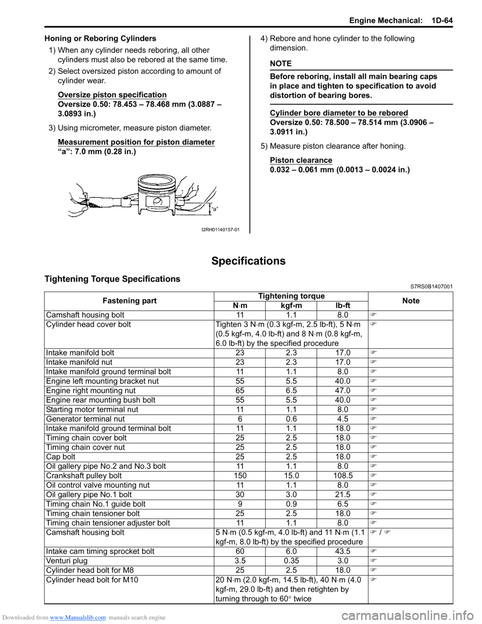
Honing or Reboring Cylinders1) When any cylinder needs reboring, all other cylinders must also be rebored at the same time.
2) Select oversized piston according to amount of cylinder wear.
Oversize piston specification
Oversize 0.50: 78.453 – 78.468 mm (3.0887 –
3.0893 in.)
3) Using micrometer, measure piston diameter. Measurement position for piston diameter
“a”: 7.0 mm (0.28 in.) 4) Rebore and hone cylinder to the following
dimension.
NOTE
Before reboring, install all main bearing caps
in place and tighten to specification to avoid
distortion of bearing bores.
Cylinder bore diameter to be rebored
Oversize 0.50: 78.500 – 78.514 mm (3.0906 –
3.0911 in.)
5) Measure piston clearance after honing. Piston clearance
0.032 – 0.061 mm (0.0013 – 0.0024 in.)
Specifications
Tightening Torque SpecificationsS7RS0B1407001
I2RH01140157-01
Fastening part Tightening torque
Note
N ⋅mkgf-mlb-ft
Camshaft housing bolt 11 1.1 8.0 �)
Cylinder head cover bolt Tighten 3 N ⋅m (0.3 kgf-m, 2.5 lb-ft), 5 N ⋅m
(0.5 kgf-m, 4.0 lb-ft) and 8 N ⋅m (0.8 kgf-m,
6.0 lb-ft) by the specified procedure �)
Intake manifold bolt 23 2.3 17.0 �)
Intake manifold nut 23 2.3 17.0 �)
Intake manifold ground terminal bolt 11 1.1 8.0 �)
Engine left mounting bracket nut 55 5.5 40.0 �)
Engine right mounting nut 65 6.5 47.0 �)
Engine rear mounting bush bolt 55 5.5 40.0 �)
Starting motor terminal nut 11 1.1 8.0 �)
Generator terminal nut 6 0.6 4.5 �)
Intake manifold ground terminal bolt 11 1.1 18.0 �)
Timing chain cover bolt 25 2.5 18.0 �)
Timing chain cover nut 25 2.5 18.0 �)
Cap bolt 25 2.5 18.0 �)
Oil gallery pipe No.2 and No.3 bolt 11 1.1 8.0 �)
Crankshaft pulley bolt 150 15.0 108.5 �)
Oil control valve mounting nut 11 1.1 8.0 �)
Oil gallery pipe No.1 bolt 30 3.0 21.5 �)
Timing chain No.1 guide bolt 9 0.9 6.5 �)
Timing chain tensioner bolt 25 2.5 18.0 �)
Timing chain tensioner adjuster bolt 11 1.1 8.0 �)
Camshaft housing bolt 5 N ⋅m (0.5 kgf-m, 4.0 lb-ft) and 11 N ⋅m (1.1
kgf-m, 8.0 lb-ft) by the specified procedure �)
/ �)
Intake cam timing sprocket bolt 60 6.0 43.5 �)
Venturi plug 3.5 0.35 3.0 �)
Cylinder head bolt for M8 25 2.5 18.0 �)
Cylinder head bolt for M10 20 N ⋅m (2.0 kgf-m, 14.5 lb-ft), 40 N ⋅m (4.0
kgf-m, 29.0 lb-ft) and then retighten by
turning through to 60 ° twice �)
Page 350 of 1496

Downloaded from www.Manualslib.com manuals search engine 1D-65 Engine Mechanical:
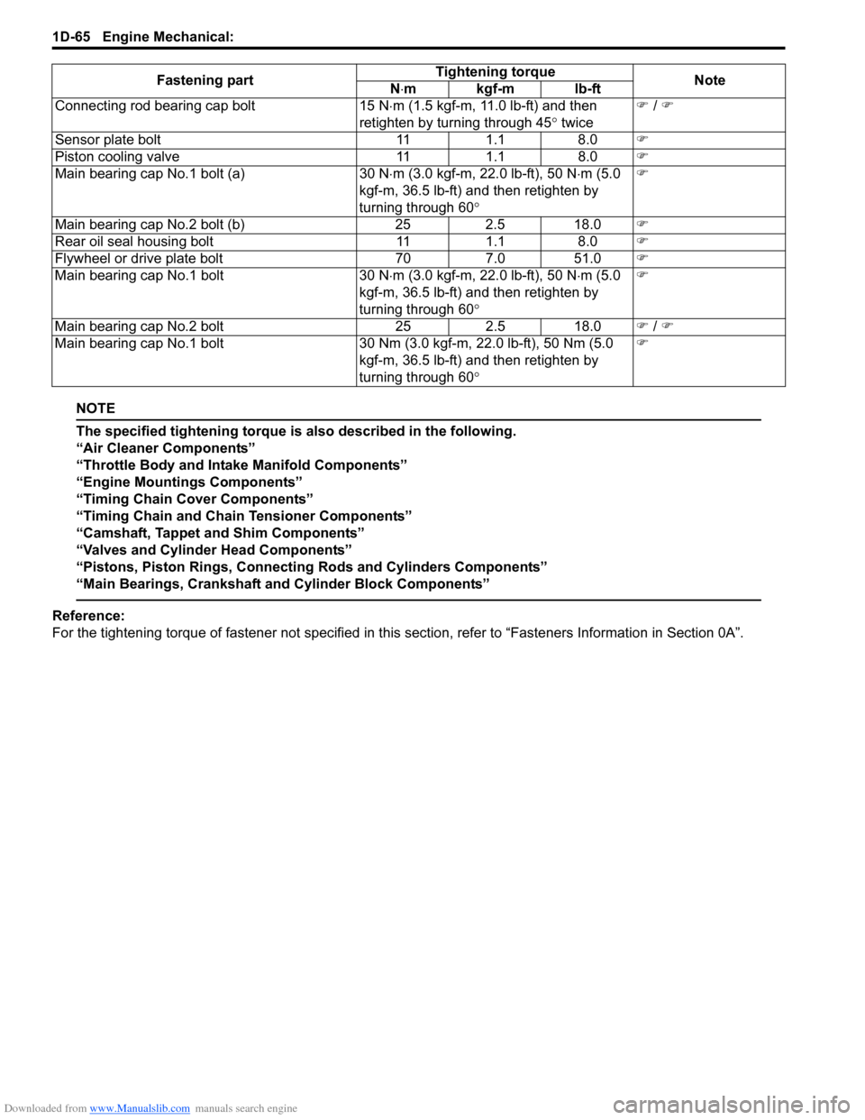
NOTE
The specified tightening torque is also described in the following.
“Air Cleaner Components”
“Throttle Body and Intake Manifold Components”
“Engine Mountings Components”
“Timing Chain Cover Components”
“Timing Chain and Chain Tensioner Components”
“Camshaft, Tappet and Shim Components”
“Valves and Cylinder Head Components”
“Pistons, Piston Rings, Connecting Rods and Cylinders Components”
“Main Bearings, Crankshaft and Cylinder Block Components”
Reference:
For the tightening torque of fastener not specified in this section, refer to “Fasteners Information in Section 0A”.
Connecting rod bearing cap bolt
15 N⋅m (1.5 kgf-m, 11.0 lb-ft) and then
retighten by turning through 45 ° twice �)
/ �)
Sensor plate bolt 111.1 8.0 �)
Piston cooling valve 111.1 8.0 �)
Main bearing cap No.1 bolt (a) 30 N⋅m (3.0 kgf-m, 22.0 lb-ft), 50 N ⋅m (5.0
kgf-m, 36.5 lb-ft) and then retighten by
turning through 60 ° �)
Main bearing cap No.2 bolt (b) 252.5 18.0 �)
Rear oil seal housing bolt 111.1 8.0 �)
Flywheel or drive plate bolt 707.0 51.0 �)
Main bearing cap No.1 bolt 30 N⋅m (3.0 kgf-m, 22.0 lb-ft), 50 N ⋅m (5.0
kgf-m, 36.5 lb-ft) and then retighten by
turning through 60 ° �)
Main bearing cap No.2 bolt 252.5 18.0 �) / �)
Main bearing cap No.1 bolt 30 Nm (3.0 kgf-m, 22.0 lb-ft), 50 Nm (5.0
kgf-m, 36.5 lb-ft) and then retighten by
turning through 60 ° �)
Fastening part
Tightening torque
Note
N ⋅mkgf-mlb-ft