2008 SUZUKI SWIFT compressor bracket
[x] Cancel search: compressor bracketPage 302 of 1496

Downloaded from www.Manualslib.com manuals search engine 1D-17 Engine Mechanical:
Engine Assembly Removal and InstallationS7RS0B1406011
NOTE
After replacing electric throttle body
assembly, perform calibration of throttle
valve referring to “Electric Throttle Body
System Calibration in Section 1C”.
Removal1) Relieve fuel pressure according to “Fuel Pressure Relief Procedure in Section 1G”.
2) Disconnect negative and pos itive cable at battery.
3) Remove battery and tray.
4) Remove engine hood after disconnecting windshield washer hose.
5) Remove right and left side engine under covers.
6) Remove A/C compressor belt by referring to “Compressor Drive Belt Remo val and Installation in
Section 7B” or “Compressor Drive Belt Removal and
Installation in Section 7B”.
7) Drain engine oil, transaxle oil and coolant.
8) Remove cowl top plate referring to “Cowl Top Components in Section 9K”.
9) Remove air cleaner assembly referring to “Air Cleaner Components”.
10) With hose connected, detach A/C compressor from its bracket (A/C model) referring to “Compressor
Assembly Removal and Installation in Section 7B” or
“Compressor Assembly Removal and Installation in
Section 7B”.
CAUTION!
Suspend removed A/C compressor at a place
where no damage will be caused during
removal and installation of engine assembly.
11) Remove intake manifold rear stiffener (1) from intake manifold and cylinder block. 12) Disconnect the following electric wires:
• MAP sensor (1)
• ECT sensor (2)
•EGR valve (3)
• CMP sensor (4)
• Electric throttle body assembly (5)
• Ignition coil assembly (6)
• Injectors (7)
• Heated oxygen sensor No. 2 (8) and No. 1 (9)
• Oil control valve (10)
• Engine oil pressure switch (11)
• CKP sensor (12)
• Knock sensor (13)
• Back up light switch (14)
• Generator (15)
• Starting motor (16)
• Ground terminal (17) from intake manifold
• Battery ground terminal (18) from exhaust manifold
• Battery ground cable (19) from transaxle
• Magnet clutch switch of A/C compressor (A/C model)
• Each wire harness clamps
• Output shaft speed sensor (VSS) (34) (A/T model)
• Solenoid valve (33) (A/T model)
• Transmission range sensor (32) (A/T model)
• Input shaft speed sensor (31) (A/T model)
13) Remove fuse box from its bracket.
14) Disconnect the following cables: • Gear select control cable (23) (M/T model)
• Gear shift control cable (24) (M/T model)
• A/T select cable (A/T model)
15) Disconnect the following hoses: • Brake booster hose (26) from intake manifold
• Radiator inlet and outlet hoses (20) from each pipe
• Heater inlet and outlet hoses (21) from each pipe
• Fuel feed hoses (22) from fuel feed pipe
• EVAP canister purge valve hose (30) from purge pipe
• A/T fluid cooler hoses (A/T model)
16) With hose connected, detach clutch operating cylinder (25). (M/T model)
CAUTION!
Suspend removed clutch operating cylinder
at a place where no damage will be caused
during removal and installation of engine
assembly.
1
I6RS0B141014-01
Page 304 of 1496
Downloaded from www.Manualslib.com manuals search engine 1D-19 Engine Mechanical:
24) Before removing engine with transaxle from engine compartment, recheck to make sure all hoses,
electric wires and cables are disconnected from
engine and transaxle.
25) Lower engine with transaxle from engine compartment.
CAUTION!
Before lowering engine, to avoid damage to
A/C compressor and clutch operating
cylinder, make clearance by rising them. Be
sure not to damage suspended A/C
compressor and clutch operating cylinder.
26) Disconnect transaxle from engine, referring to “Manual Transaxle Unit Dismounting and
Remounting in Section 5B” or “Automatic Transaxle
Unit Dismounting and Re mounting in Section 5A”.
27) For M/T model, remove clutch cover and clutch disk referring to “Clutch Cover, Clutch Disc and Flywheel
Removal and Installa tion in Section 5C”.
Installation 1) For M/T model, install clutch cover and clutch disk referring to “Clutch Cover, Clutch Disc and Flywheel
Removal and Installa tion in Section 5C”.
2) Connect transaxle to engine referring to “Manual Transaxle Unit Dismounting and Remounting in
Section 5B” or “Automatic Transaxle Unit
Dismounting and Remounting in Section 5A”.
3) Lift engine and transaxle into engine compartment with jack.
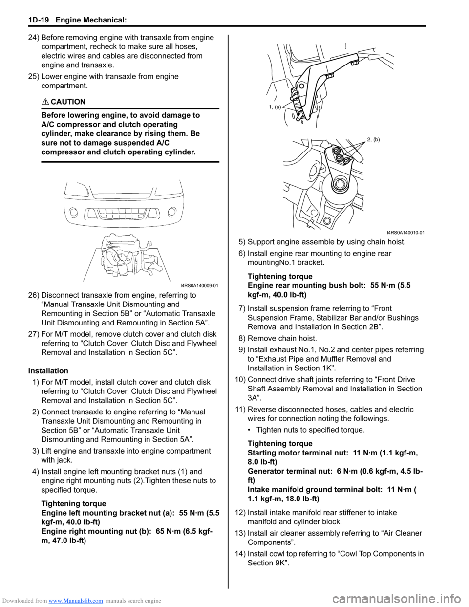
4) Install engine left mounting bracket nuts (1) and engine right mounting nuts (2).Tighten these nuts to
specified torque.
Tightening torque
Engine left mounting bracket nut (a): 55 N·m (5.5
kgf-m, 40.0 lb-ft)
Engine right mounting nut (b): 65 N·m (6.5 kgf-
m, 47.0 lb-ft) 5) Support engine assemble by using chain hoist.
6) Install engine rear mounting to engine rear
mountingNo.1 bracket.
Tightening torque
Engine rear mounting bush bolt: 55 N·m (5.5
kgf-m, 40.0 lb-ft)
7) Install suspension frame referring to “Front Suspension Frame, Stabiliz er Bar and/or Bushings
Removal and Installati on in Section 2B”.
8) Remove chain hoist.
9) Install exhaust No.1, No.2 and center pipes referring to “Exhaust Pipe and Muffler Removal and
Installation in Section 1K”.
10) Connect drive shaft joints referring to “Front Drive Shaft Assembly Removal and Installation in Section
3A”.
11) Reverse disconnected hoses, cables and electric wires for connection noting the followings.
• Tighten nuts to specified torque.
Tightening torque
Starting motor terminal nut: 11 N·m (1.1 kgf-m,
8.0 lb-ft)
Generator terminal nut: 6 N·m (0.6 kgf-m, 4.5 lb-
ft)
Intake manifold ground terminal bolt: 11 N·m (
1.1 kgf-m, 18.0 lb-ft)
12) Install intake manifold rear stiffener to intake
manifold and cylinder block.
13) Install air cleaner assembly referring to “Air Cleaner Components”.
14) Install cowl top referring to “Cowl Top Components in
Section 9K”.
I4RS0A140009-01
1, (a)
2, (b)
I4RS0A140010-01
Page 305 of 1496

Downloaded from www.Manualslib.com manuals search engine Engine Mechanical: 1D-20
15) Install A/C compressor to its bracket (if equipped) referring to “Compressor Assembly Removal and
Installation in Section 7B” or “Compressor Assembly
Removal and Installa tion in Section 7B”.
16) Adjust A/C compressor belt tension (if equipped) referring to “Compressor Drive Belt Inspection and
Adjustment in Section 7B” or “Compressor Drive Belt
Inspection and Adjustment in Section 7B”.
17) Check to ensure that a ll removed parts are back in
place.
Reinstall any necessary parts which have not been
reinstalled.
18) Refill cooling system with coolant referring to “Cooling System Flush and Refill in Section 1F”. 19) Refill engine with engine oil
referring to “Engine Oil
and Filter Change in Section 0B”.
20) Refill transaxle with transa xle oil referring to“Manual
Transaxle Oil Change in Section 5B” or “A/T Fluid
Change in Section 5A”.
21) Install battery and tray.
22) Connect positive and negative cable at battery.
23) Install engine hood and connect windshield washer hose.
24) Verify that there is no fu el leakage, coolant leakage,
oil leakage and exhaust gas leakage at each
connection.
Timing Chain Cover ComponentsS7RS0B1406012
I6RS0C140015-02
1. Crankshaft pulley bolt 13. Oil gallery pipe No.2 bolt
2. Crankshaft pulley 14. Oil gallery pipe No.3
3. Oil seal : Apply engine oil to oil seal lip. 15. Oil gallery pipe No.3 bolt
4. Timing chain cover : Apply sealant 99000-31140 to the mating surface of cylinder and cylinder head.
: Apply sealant 99000-31260 to the mating surface of timing chain cover referring to the
figure of Step 4) of “Installation” under “Timing Chain Cover Removal and Installation”. 16. O-ring
: Apply engine oil.
5. Pin 17. Oil control valve
6. Cap bolt 18. Oil control valve mounting nut
7. Timing chain cover mounting bolts 19. Cap
8. Timing chain cover mounting nut : 11 N ⋅m (1.1 kgf-m, 8.0 lb-ft)
9. Oil gallery pipe No.1 :25 N⋅m (2.5 kgf-m, 18.0 lb-ft)
Page 418 of 1496
Downloaded from www.Manualslib.com manuals search engine 1J-8 Charging System:
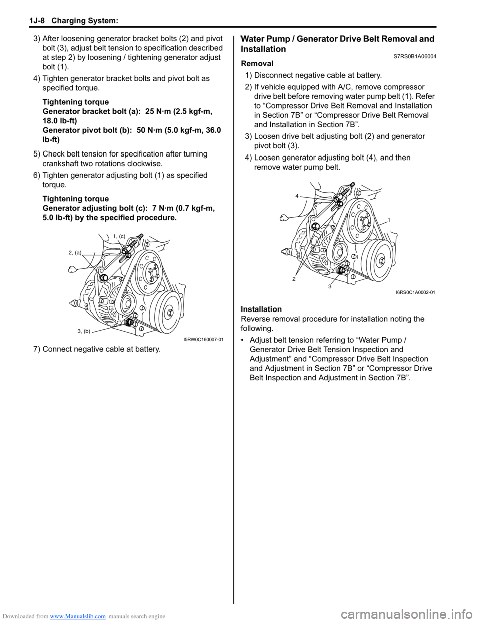
3) After loosening generator bracket bolts (2) and pivot bolt (3), adjust belt tensio n to specification described
at step 2) by loosening / tightening generator adjust
bolt (1).
4) Tighten generator bracket bolts and pivot bolt as specified torque.
Tightening torque
Generator bracket bolt (a): 25 N·m (2.5 kgf-m,
18.0 lb-ft)
Generator pivot bolt (b): 50 N·m (5.0 kgf-m, 36.0
lb-ft)
5) Check belt tension for specification after turning crankshaft two rotations clockwise.
6) Tighten generator adjusting bolt (1) as specified torque.
Tightening torque
Generator adjusting bolt (c): 7 N·m (0.7 kgf-m,
5.0 lb-ft) by the specified procedure.
7) Connect negative cable at battery.Water Pump / Generator Drive Belt Removal and
Installation
S7RS0B1A06004
Removal 1) Disconnect negative cable at battery.
2) If vehicle equipped with A/C, remove compressor drive belt before removing water pump belt (1). Refer
to “Compressor Drive Belt Removal and Installation
in Section 7B” or “Compr essor Drive Belt Removal
and Installation in Section 7B”.
3) Loosen drive belt adjusting bolt (2) and generator pivot bolt (3).
4) Loosen generator adjusting bolt (4), and then remove water pump belt.
Installation
Reverse removal procedure for installation noting the
following.
• Adjust belt tension referring to “Water Pump / Generator Drive Belt Tension Inspection and
Adjustment” and “Compressor Drive Belt Inspection
and Adjustment in Section 7B” or “Compressor Drive
Belt Inspection and Adjustment in Section 7B”.
1, (c)
2, (a)
3, (b)
I5RW0C160007-01
4
23
1
I6RS0C1A0002-01
Page 670 of 1496
Downloaded from www.Manualslib.com manuals search engine 5A-26 Automatic Transmission/Transaxle:
TRANSAXLE RANGE
Transaxle range detected by signal fed from
transmission range sensor.
D RANGE SIGNAL
ON: Signal which TCM require ECM to increase idle
speed
OFF: Signal which TCM does not require ECM to
increase idle speed
THROTTLE POSITION (%)
Throttle opening ratio computed by CAN signal from
ECM.
BRAKE SWITCH
Inputted signal from brake light switch on pedal bracket.
ON: Brake pedal depressed
OFF: Brake pedal released
TORQUE REDUCTION SIGNAL
ON: Signal which TCM require ECM to reduce output
torque at shifting gear
OFF: Signal which TCM does not require ECM to reduce
output torque
ENGINE COOLANT TEMPERATURE ( °C, °F)
Engine coolant temperature computed by CAN signal
from ECM. AIR CONDITIONER SIGNAL
ON: Signal which inform that air conditioner compressor
is turned ON.
OFF: Signal which inform that air conditioner
compressor is not turned ON.
ENGINE TORQUE SIGNAL (N
⋅m)
Engine torque computed by duty pulse signal outputted
from ECM.
SLIP RPM (RPM)
This parameter indicates slip ping rotation in the torque
converter (difference between input shaft rotation and
engine rotation)
MIL REQUEST
ON: Signal which TCM requires combination meter to
turn on malfunction indicator lamp.
OFF: Signal which TCM does not require combination
meter to turn on malf unction indicator lamp.
FUEL CUT FLAG
ON: Signal which inform that fuel cut is operating.
OFF: Signal which inform that fuel cut is not operating.
A/T Basic CheckS7RS0B5104010
This check is important for troubleshooting when TCM has detected no DTC and no abnormality has been noted in
“Visual Inspection”. Fo llow the flow carefully.
Step Action YesNo
1 Was “A/T System Check” preformed? Go to Step 2.Go to “A/T System
Check”.
2 Perform “Road Test”.
Is it OK? Go to Step 3.
Proceed to
“Troubleshooting” in
“Road Test”.
3 Perform “Manual Road Test”.
Is it OK? Go to Step 4.
Proceed to
“Troubleshooting” in
“Manual Road Test”.
4 Perform “Engine Brake Test”.
Is it OK? Go to Step 5.
Proceed to
“Troubleshooting” in
“Engine Brake Test”.
5 Perform “Stall Test”.
Is it OK? Go to Step 6.
Proceed to
“Troubleshooting” in
“Stall Test”.
6 Perform “Time Lag Test”.
Is it OK? Go to Step 7.
Proceed to
“Troubleshooting” in
“Time Lag Test”.
7 Perform “Line Pressure Test”.
Is it OK? Go to Step 8.
Proceed to
“Troubleshooting” in
“Line Pressure Test”.
8 Proceed to “Trouble Diag nosis 1” in “A/T Symptom
Diagnosis”.
Is trouble identified? Repair or replace faulty
parts.
Go to Step 9.
Page 957 of 1496
Downloaded from www.Manualslib.com manuals search engine Air Conditioning System: Manual Type 7B-9
Abnormal Noise Symptom Diagnosis of A/C SystemS7RS0B7214002
Abnormal Noise from Compressor
Abnormal Noise from Magnetic Clutch
Abnormal Noise from Tubing
Abnormal Noise from Condenser Assembly
Abnormal Noise from Crankshaft PulleyInsufficient airflow of
cooled air
A/C evaporator clogged or frosted
Check A/C evaporator and evaporator
thermistor (evaporator temperature sensor)
referring to “Evaporator Inspection” and
“Evaporator Thermistor (Evaporator
Temperature Sensor) Inspection”.
Air leaking from HVAC unit or air duct Repair as necessary.
Blower motor faulty Check blower motor referring to “Blower Motor
Inspection in Section 7A”.
Wiring or grounding faulty Repair as necessary.
Condition Possible cause Correction / Reference Item
Condition
Possible cause Correction / Reference Item
During compressor
operation, a rumbling
noise is heard
proportional to engine
revolutions Inadequate clearance in scroll area
Replace compressor.
A loud noise is heard at a
certain rpm,
disproportionately to
engine revolution Loose or faulty compressor drive belt
Adjust drive belt tension or replace drive belt.
Loose compressor mounting bolts Retighten mounting bolts.
A loud rattle is heard at
low engine rpm Loose compressor clutch plate bolt
Retighten clutch plate bolt.
Replace compressor if it was operated in this
condition for a long time.
Condition Possible cause Correction / Reference Item
A rumbling noise is heard
when compressor is not
in operation Worn or damaged bearings
Replace magnet clutch assembly.
A chattering noise is
heard when compressor
is in operation Faulty magnet clutch clearance
(excessive clearance)
Adjust magnet clutch clearance.
Worn magnet clutch friction surface Replace magnet clutch assembly.
Compressor oil leaked from shaft seal,
contaminating the friction surface Replace compressor body assembly.
Condition
Possible cause Correction / Reference Item
A droning noise is heard
from inside of the vehicle,
but not particularly
noticeable in engine
compartment Faulty tubing clamps
Reposition clamps or increase the number of
clamps.
Resonance caused by pulsation from
variations in re frigerant pressure Attach a silencer to tubing, or modify its
position and length.
Condition
Possible cause Correction / Reference Item
Considerable vibration in
condenser assembly Resonance from condenser assembly
bracket and body Firmly insert a silenc
er between condenser
assembly bracket and body.
Condition Possible cause Correction / Reference Item
A large rattling noise is
heard at idle or sudden
acceleration Loosen crankshaft pulley bolt
Retighten bolt.
Page 976 of 1496
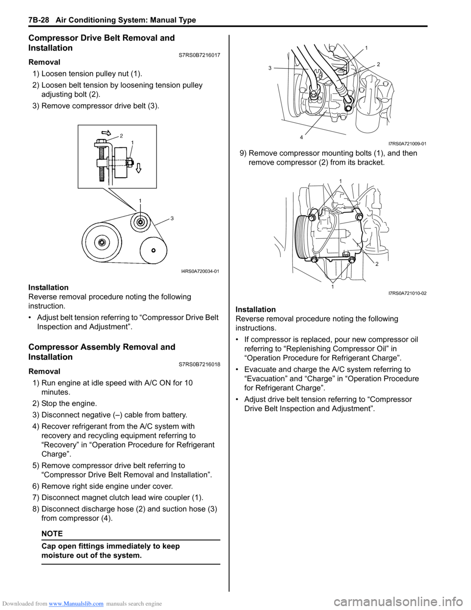
Downloaded from www.Manualslib.com manuals search engine 7B-28 Air Conditioning System: Manual Type
Compressor Drive Belt Removal and
Installation
S7RS0B7216017
Removal1) Loosen tension pulley nut (1).
2) Loosen belt tension by loosening tension pulley adjusting bolt (2).
3) Remove compressor drive belt (3).
Installation
Reverse removal procedure noting the following
instruction.
• Adjust belt tension referring to “Compressor Drive Belt Inspection and Adjustment”.
Compressor Assembly Removal and
Installation
S7RS0B7216018
Removal
1) Run engine at idle speed with A/C ON for 10 minutes.
2) Stop the engine.
3) Disconnect negative (–) cable from battery.
4) Recover refrigerant fr om the A/C system with
recovery and recycling equipment referring to
“Recovery” in “Operation Procedure for Refrigerant
Charge”.
5) Remove compressor drive belt referring to “Compressor Drive Belt Re moval and Installation”.
6) Remove right side engine under cover.
7) Disconnect magnet clutch lead wire coupler (1).
8) Disconnect discharge hose (2) and suction hose (3) from compressor (4).
NOTE
Cap open fittings immediately to keep
moisture out of the system.
9) Remove compressor mounting bolts (1), and then remove compressor (2 ) from its bracket.
Installation
Reverse removal procedure noting the following
instructions.
• If compressor is replaced, pour new compressor oil referring to “Replenishi ng Compressor Oil” in
“Operation Procedure for Refrigerant Charge”.
• Evacuate and charge the A/C system referring to “Evacuation” and “Charge” in “Operation Procedure
for Refrigerant Charge”.
• Adjust drive belt tension referring to “Compressor Drive Belt Inspecti on and Adjustment”.
I4RS0A720034-01
3
4 2
1
I7RS0A721009-01
1
1 2
I7RS0A721010-02