2008 SUZUKI SWIFT floor carpet removal
[x] Cancel search: floor carpet removalPage 36 of 1496
Downloaded from www.Manualslib.com manuals search engine 0B-6 Maintenance and Lubrication:
Exhaust System InspectionS7RS0B0206006
WARNING!
To avoid danger of being burned, do not
touch exhaust system when it is still hot.
Any service on exhaust system should be
performed when it is cool.
When carrying out periodic maintenance, or the vehicle
is raised for other service, check exhaust system as
follows:
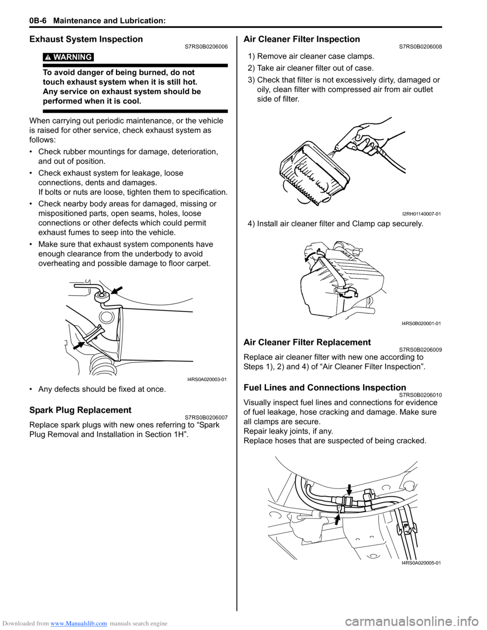
• Check rubber mountings for damage, deterioration, and out of position.
• Check exhaust system for leakage, loose connections, dents and damages.
If bolts or nuts are loose, tighten them to specification.
• Check nearby body areas for damaged, missing or mispositioned parts, ope n seams, holes, loose
connections or other defects which could permit
exhaust fumes to seep into the vehicle.
• Make sure that exhaust system components have enough clearance from the underbody to avoid
overheating and possible damage to floor carpet.
• Any defects should be fixed at once.
Spark Plug ReplacementS7RS0B0206007
Replace spark plugs with new ones referring to “Spark
Plug Removal and Installation in Section 1H”.
Air Cleaner Filter InspectionS7RS0B0206008
1) Remove air cleaner case clamps.
2) Take air cleaner filter out of case.
3) Check that filter is not excessively dirty, damaged or oily, clean filter with compressed air from air outlet
side of filter.
4) Install air cleaner filter and Clamp cap securely.
Air Cleaner Filter ReplacementS7RS0B0206009
Replace air cleaner filter with new one according to
Steps 1), 2) and 4) of “Air Cleaner Filter Inspection”.
Fuel Lines and Connections InspectionS7RS0B0206010
Visually inspect fuel lines and connections for evidence
of fuel leakage, hose cracking and damage. Make sure
all clamps are secure.
Repair leaky joints, if any.
Replace hoses that are suspected of being cracked.
I4RS0A020003-01
I2RH01140007-01
I4RS0B020001-01
I4RS0A020005-01
Page 210 of 1496
Downloaded from www.Manualslib.com manuals search engine 1A-160 Engine General Information and Diagnosis:
DTC Troubleshooting
NOTE
• When measuring circuit voltage, resistance and/or pulse signal at ECM connector, connect the
special tool to ECM and/or the ECM connectors re ferring to “Inspection of ECM and Its Circuits”.
• Upon completion of inspection and repair work, perform “DTC Confirmation Procedure” and confirm that the trouble has been corrected.
Step Action YesNo
1 Was “Engine and Emission Control System Check”
performed? Go to Step 2.
Go to “Engine and
Emission Control
System Check”.
2 APP sensor mounting check
1) Check that APP sensor has been mounted to vehicle
body properly (no pinched floor carpet, etc.).
It is OK? Go to Step 3.
Reinstall APP sensor
properly referring to
“APP Sensor Assembly
Removal and
Installation in Section
1C”.
3 APP sensor (main) and its circuit check
1) Connect scan tool to DLC with ignition switch turned
OFF.
2) Turn ON ignition switch, check “APP Sensor 1 Volt” displayed on scan tool.
Is displayed voltage below 0.384 V? Go to Step 4.
Intermittent trouble.
Check for intermittent
referring to “Intermittent
and Poor Connection
Inspection in Section
00”.
4 ECM voltage check
1) Disconnect connector from APP sensor with ignition
switch turned OFF.
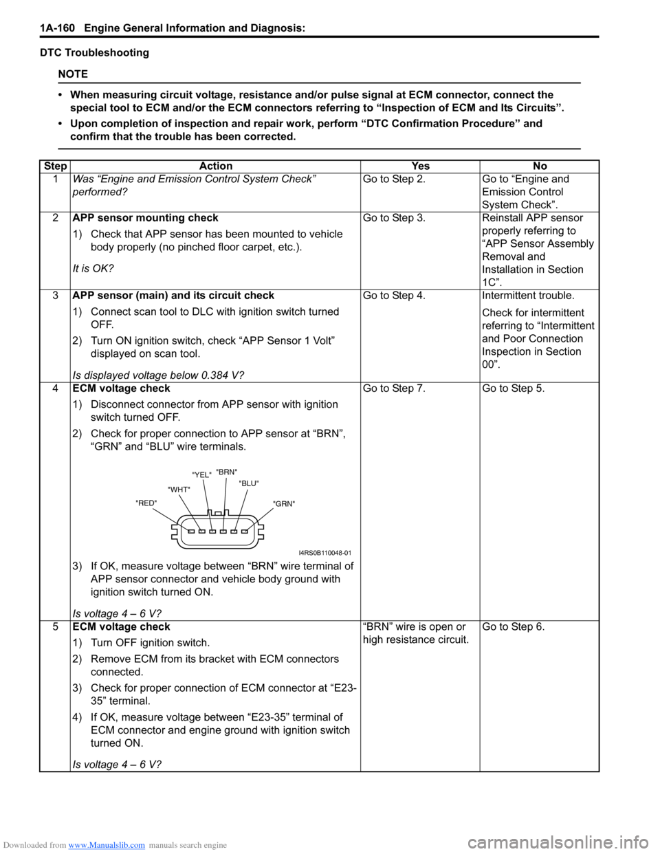
2) Check for proper connection to APP sensor at “BRN”, “GRN” and “BLU” wire terminals.
3) If OK, measure voltage between “BRN” wire terminal of APP sensor connector and vehicle body ground with
ignition switch turned ON.
Is voltage 4 – 6 V? Go to Step 7.
Go to Step 5.
5 ECM voltage check
1) Turn OFF ignition switch.
2) Remove ECM from its br acket with ECM connectors
connected.
3) Check for proper connection of ECM connector at “E23- 35” terminal.
4) If OK, measure voltage between “E23-35” terminal of ECM connector and engine ground with ignition switch
turned ON.
Is voltage 4 – 6 V? “BRN” wire is open or
high resistance circuit.
Go to Step 6.
"GRN"
"BLU"
"BRN"
"YEL"
"WHT"
"RED"
I4RS0B110048-01
Page 212 of 1496
Downloaded from www.Manualslib.com manuals search engine 1A-162 Engine General Information and Diagnosis:
DTC Troubleshooting
NOTE
• When measuring circuit voltage, resistance and/or pulse signal at ECM connector, connect the
special tool to ECM and/or the ECM connectors re ferring to “Inspection of ECM and Its Circuits”.
• Upon completion of inspection and repair work, perform “DTC Confirmation Procedure” and confirm that the trouble has been corrected.
Step Action YesNo
1 Was “Engine and Emission Control System Check”
performed? Go to Step 2.
Go to “Engine and
Emission Control
System Check”.
2 APP sensor mounting check
1) Check that APP sensor has been mounted to vehicle
body properly (no pinched floor carpet, etc.).
Is it OK? Go to Step 3.
Reinstall APP sensor
properly referring to
“APP Sensor Assembly
Removal and
Installation in Section
1C”.
3 APP sensor (main) and its circuit check
1) Connect scan tool to DLC with ignition switch turned
OFF.
2) Turn ON ignition switch, check “APP Sensor 1 Volt” displayed on scan tool.
Is displayed voltage 4.75 V or more? Go to Step 4.
Intermittent trouble.
Check for intermittent
referring to “Intermittent
and Poor Connection
Inspection in Section
00”
4 ECM voltage check
1) Disconnect connector from APP sensor with ignition
switch turned OFF.
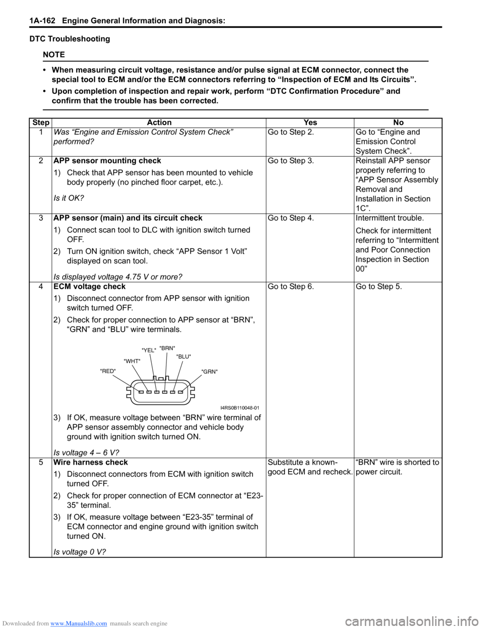
2) Check for proper connection to APP sensor at “BRN”, “GRN” and “BLU” wire terminals.
3) If OK, measure voltage between “BRN” wire terminal of APP sensor assembly connector and vehicle body
ground with ignition switch turned ON.
Is voltage 4 – 6 V? Go to Step 6.
Go to Step 5.
5 Wire harness check
1) Disconnect connectors from ECM with ignition switch
turned OFF.
2) Check for proper connection of ECM connector at “E23- 35” terminal.
3) If OK, measure voltage between “E23-35” terminal of ECM connector and engine ground with ignition switch
turned ON.
Is voltage 0 V? Substitute a known-
good ECM and recheck.
“BRN” wire is shorted to
power circuit.
"GRN"
"BLU"
"BRN"
"YEL"
"WHT"
"RED"
I4RS0B110048-01
Page 214 of 1496
Downloaded from www.Manualslib.com manuals search engine 1A-164 Engine General Information and Diagnosis:
DTC P2127: Throttle Pedal Position Sensor / Switch “E” (Sub) Circuit Low InputS7RS0B1104074
Wiring Diagram
Refer to “DTC P2122: Throttle / Pedal Position Sensor / Switch “D” (Main) Circuit Low Input”.
DTC Detecting Condition and Trouble Area
DTC Confirmation Procedure 1) With ignition switch turned OFF, connect scan tool.
2) Turn ON ignition switch and clear DTC using scan tool.
3) Keep the accelerator pedal at idle position for 2 seconds.
4) Keep the accelerator pedal at fully depressed position for 2 seconds.
5) Repeat Step 3) and 4) for 3 times.
6) Check DTC.
DTC Troubleshooting
NOTE
• When measuring circuit voltage, resistance and/ or pulse signal at ECM connector, connect the
special tool to ECM and/or the ECM connectors re ferring to “Inspection of ECM and Its Circuits”.
• Upon completion of inspection and repair work, perform “DTC Confirmation Procedure” and confirm that the trouble has been corrected.
DTC detecting condition Trouble area
Output voltage of APP sensor (sub) is less than specified
value for 0.2 seconds continuously.
(1 driving detection logic) • APP sensor (sub) circuit
• APP sensor
•ECM
• Incorrect mounting of APP sensor
Step
Action YesNo
1 Was “Engine and Emission Control System Check”
performed? Go to Step 2.
Go to “Engine and
Emission Control
System Check”.
2 APP sensor mounting check
1) Check that APP sensor has been mounted to vehicle
body properly (no pinched floor carpet, etc.).
Is it OK? Go to Step 3.
Reinstall APP sensor
properly referring to
“APP Sensor Assembly
Removal and
Installation in Section
1C”.
3 APP sensor (sub) and its circuit check
1) Connect scan tool to DLC with ignition switch turned
OFF.
2) Turn ON ignition switch, check “APP Sensor 2 Volt” displayed on scan tool.
Is displayed voltage below 0.384 V? Go to Step 4.
Intermittent trouble.
Check for intermittent
referring to “Intermittent
and Poor Connection
Inspection in Section
00”.
Page 216 of 1496
Downloaded from www.Manualslib.com manuals search engine 1A-166 Engine General Information and Diagnosis:
DTC P2128: Throttle / Pedal Position Sensor / Switch “E” (Sub) Circuit High InputS7RS0B1104075
Wiring Diagram
Refer to “DTC P2122: Throttle / Pedal Position Sensor / Switch “D” (Main) Circuit Low Input”.
DTC Detecting Condition and Trouble Area
DTC Confirmation Procedure 1) With ignition switch turned OFF, connect scan tool.
2) Turn ON ignition switch and clear DTC using scan tool.
3) Keep the accelerator pedal at idle position for 2 seconds.
4) Keep the accelerator pedal at fully depressed position for 2 seconds.
5) Repeat Step 3) and 4) for 3 times.
6) Check DTC.
DTC Troubleshooting
NOTE
• When measuring circuit voltage, resistance and/ or pulse signal at ECM connector, connect the
special tool to ECM and/or the ECM connectors re ferring to “Inspection of ECM and Its Circuits”.
• Upon completion of inspection and repair work, perform “DTC Confirmation Procedure” and confirm that the trouble has been corrected.
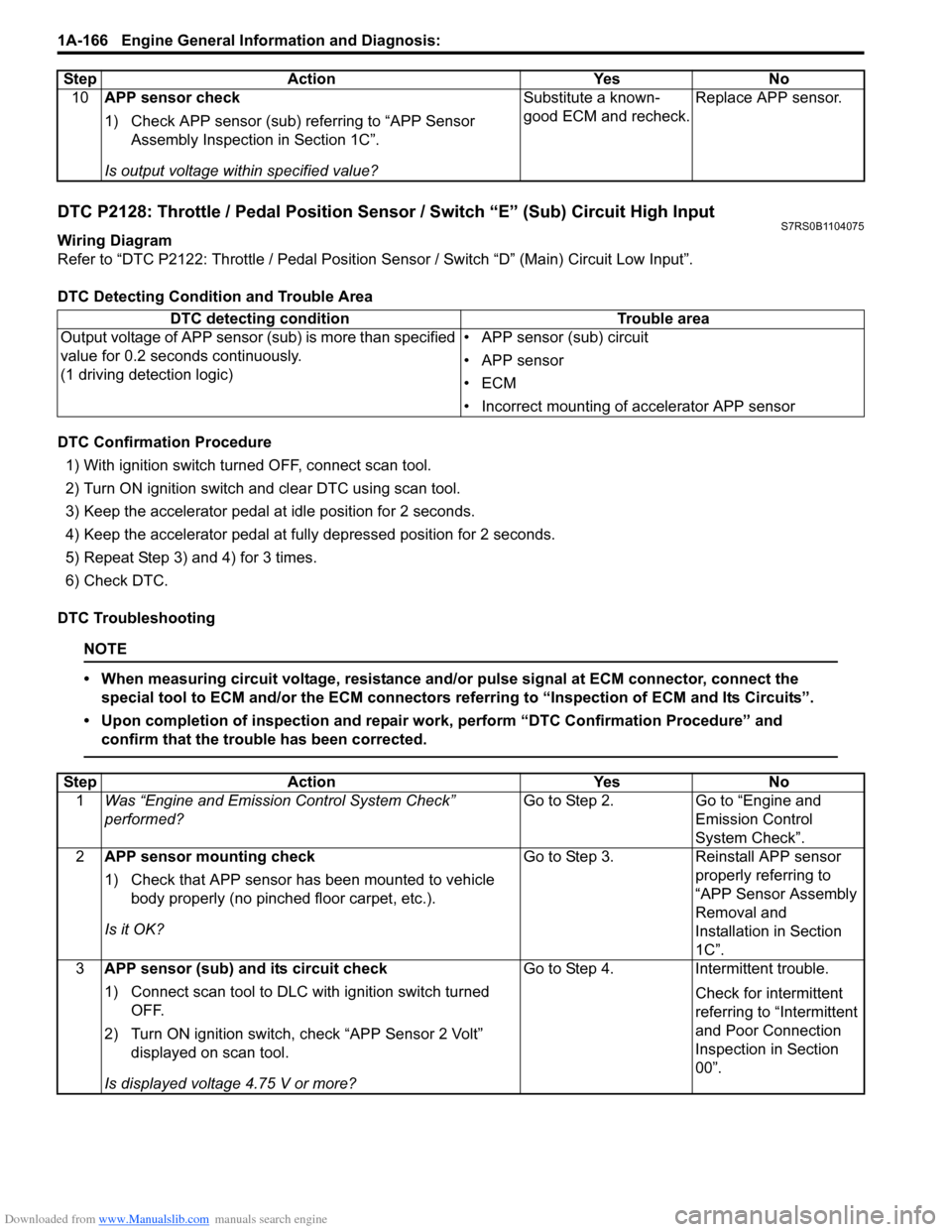
10 APP sensor check
1) Check APP sensor (sub) re ferring to “APP Sensor
Assembly Inspection in Section 1C”.
Is output voltage within specified value? Substitute a known-
good ECM and recheck.
Replace APP sensor.
Step Action Yes No
DTC detecting condition
Trouble area
Output voltage of APP sensor (s ub) is more than specified
value for 0.2 seconds continuously.
(1 driving detection logic) • APP sensor (sub) circuit
• APP sensor
•ECM
• Incorrect mounting of
accelerator APP sensor
Step Action YesNo
1 Was “Engine and Emission Control System Check”
performed? Go to Step 2.
Go to “Engine and
Emission Control
System Check”.
2 APP sensor mounting check
1) Check that APP sensor has been mounted to vehicle
body properly (no pinched floor carpet, etc.).
Is it OK? Go to Step 3.
Reinstall APP sensor
properly referring to
“APP Sensor Assembly
Removal and
Installation in Section
1C”.
3 APP sensor (sub) and its circuit check
1) Connect scan tool to DLC with ignition switch turned
OFF.
2) Turn ON ignition switch, check “APP Sensor 2 Volt” displayed on scan tool.
Is displayed voltage 4.75 V or more? Go to Step 4.
Intermittent trouble.
Check for intermittent
referring to “Intermittent
and Poor Connection
Inspection in Section
00”.
Page 277 of 1496
Downloaded from www.Manualslib.com manuals search engine Engine Electrical Devices: 1C-5
Electric Throttle Body System CalibrationS7RS0B1306004
NOTE
If working the service described under the
“Precautions of Electric Throttle Body
System Calibration in Section 1A” perform
following steps for electric throttle body
system calibration.
1) If electric throttle body assembly and/or APP sensor
assembly are replaced, perform following steps.
a) Disconnect negative cable at battery for 20 seconds or more for the purpose of clearing
calibration data of closed throttle position from
memory in ECM.
b) Connect negative cable to battery.
2) Keep ignition switch at ON position for 5 seconds or more without running engine.
APP Sensor Assembly On-Vehicle InspectionS7RS0B1306005
1) Check that APP sensor a ssembly has been mounted
to vehicle body properly (no pinched floor carpet,
etc.).
If mounting is not pro perly, reinstall APP sensor
assembly properly refe rring to “APP Sensor
Assembly Removal and Installation”.
2) Connect scan tool to DLC with ignition switch turned OFF.
3) Turn ON ignition switch and select “Data List” mode on scan tool.
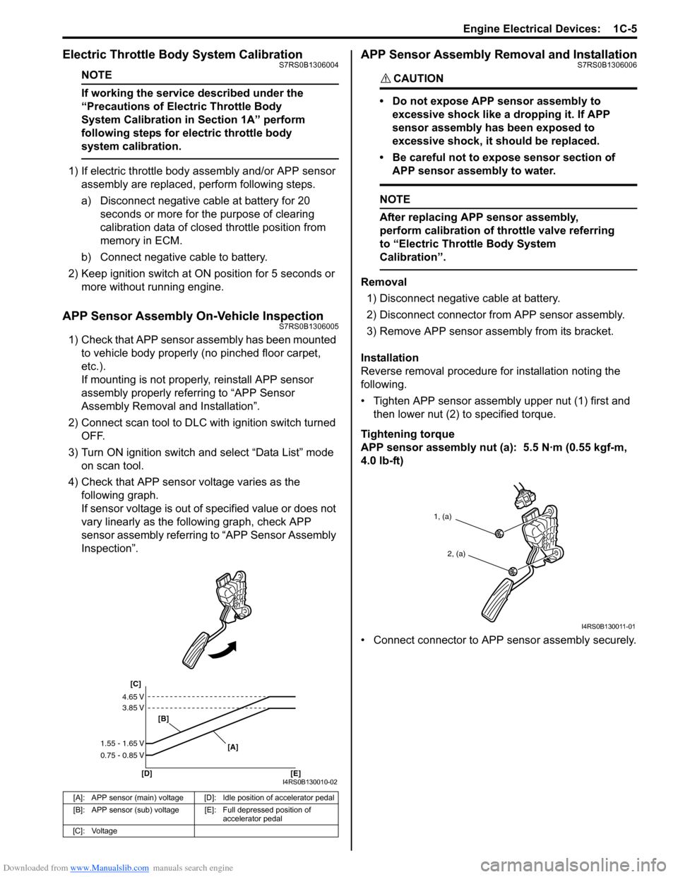
4) Check that APP sensor voltage varies as the following graph.
If sensor voltage is out of specified value or does not
vary linearly as the fo llowing graph, check APP
sensor assembly referring to “APP Sensor Assembly
Inspection”.
APP Sensor Assembly Removal and InstallationS7RS0B1306006
CAUTION!
• Do not expose APP sensor assembly to
excessive shock like a dropping it. If APP
sensor assembly has been exposed to
excessive shock, it should be replaced.
• Be careful not to expose sensor section of APP sensor assembly to water.
NOTE
After replacing APP sensor assembly,
perform calibration of th rottle valve referring
to “Electric Throttle Body System
Calibration”.
Removal
1) Disconnect negative cable at battery.
2) Disconnect connector from APP sensor assembly.
3) Remove APP sensor asse mbly from its bracket.
Installation
Reverse removal procedure for installation noting the
following.
• Tighten APP sensor assembly upper nut (1) first and then lower nut (2) to specified torque.
Tightening torque
APP sensor assembly nut (a): 5.5 N·m (0.55 kgf-m,
4.0 lb-ft)
• Connect connector to APP sensor assembly securely.
[A]: APP sensor (main) voltage [D]: Idle position of accelerator pedal
[B]: APP sensor (sub) voltage [E]: Full depressed position of
accelerator pedal
[C]: Voltage
[C]
[B]
[D] [E] [A]
4.65 V
3.85 V
1.55 - 1.65 V
0.75 - 0.85 V
I4RS0B130010-02
1, (a)
2, (a)
I4RS0B130011-01
Page 572 of 1496
Downloaded from www.Manualslib.com manuals search engine 4E-33 ABS:
Rear Wheel Speed Sensor Removal and
Installation
S7RS0B4506008
Removal1) Disconnect negative (–) cable from battery.
2) Remove quarter inner trim to brake referring to “Floor Carpet Removal a nd Installation in Section
9H”.
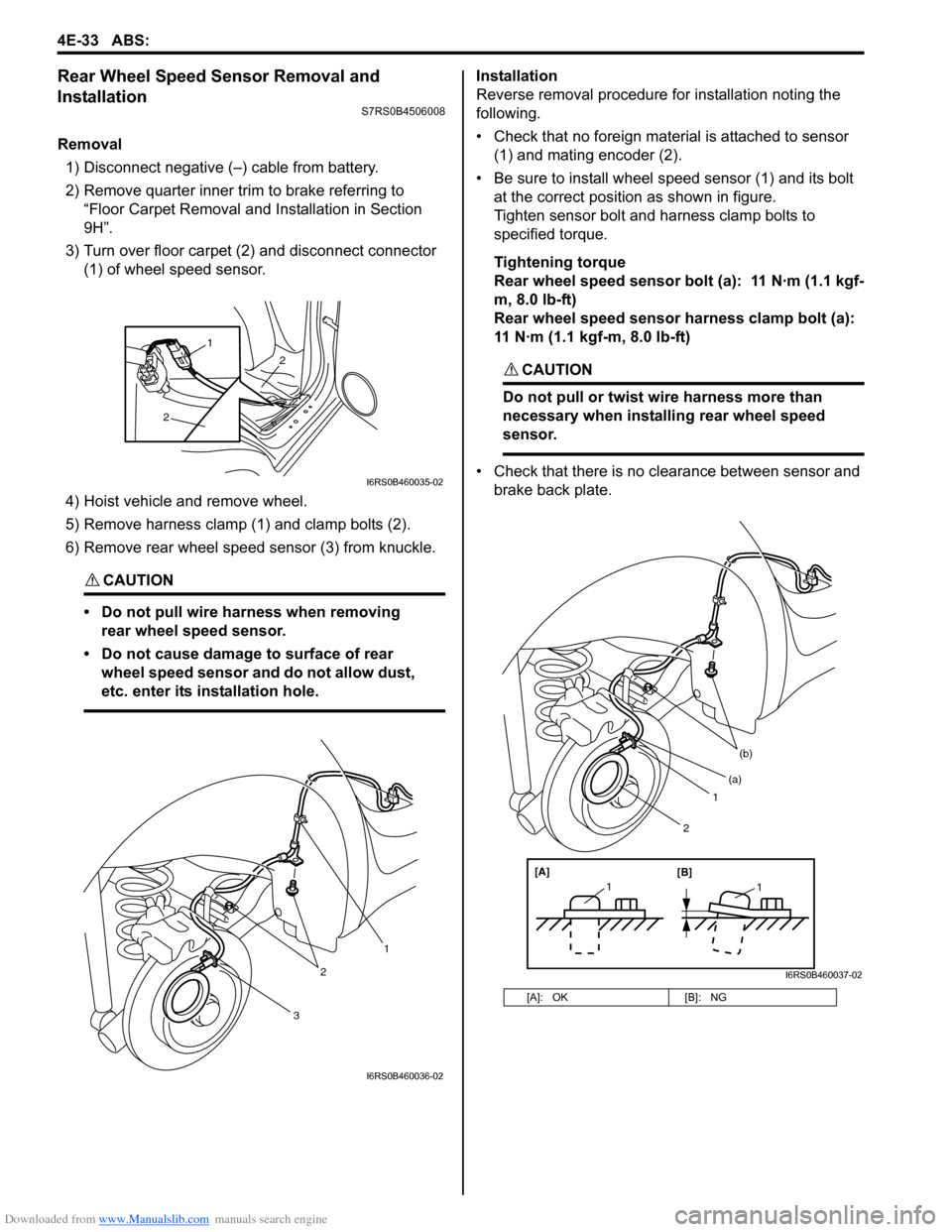
3) Turn over floor carpet (2) and disconnect connector (1) of wheel speed sensor.
4) Hoist vehicle and remove wheel.
5) Remove harness clamp (1) and clamp bolts (2).
6) Remove rear wheel speed sensor (3) from knuckle.
CAUTION!
• Do not pull wire harness when removing rear wheel speed sensor.
• Do not cause damage to surface of rear wheel speed sensor and do not allow dust,
etc. enter its installation hole.
Installation
Reverse removal procedure for installation noting the
following.
• Check that no foreign material is attached to sensor (1) and mating encoder (2).
• Be sure to install wheel speed sensor (1) and its bolt at the correct position as shown in figure.
Tighten sensor bolt and harness clamp bolts to
specified torque.
Tightening torque
Rear wheel speed sensor bolt (a): 11 N·m (1.1 kgf-
m, 8.0 lb-ft)
Rear wheel speed sensor harness clamp bolt (a):
11 N·m (1.1 kgf-m, 8.0 lb-ft)
CAUTION!
Do not pull or twist wire harness more than
necessary when installing rear wheel speed
sensor.
• Check that there is no clearance between sensor and brake back plate.
2
2
1
I6RS0B460035-02
3
2
1
I6RS0B460036-02
[A]: OK [B]: NG
1
(b)
[A][B]
11
(a)
2
I6RS0B460037-02
Page 633 of 1496
Downloaded from www.Manualslib.com manuals search engine Electronic Stability Program: 4F-59
Installation
CAUTION!
Do not pull or twist wire harness more than
necessary when installing front wheel speed
sensor.
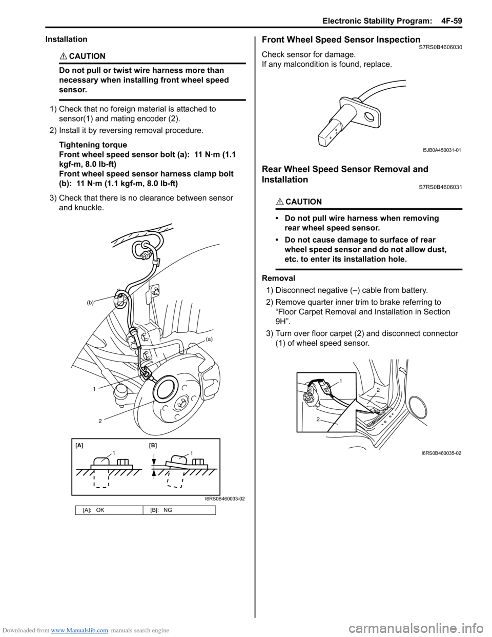
1) Check that no foreign material is attached to sensor(1) and mating encoder (2).
2) Install it by reversing removal procedure.
Tightening torque
Front wheel speed sensor bolt (a): 11 N·m (1.1
kgf-m, 8.0 lb-ft)
Front wheel speed sensor harness clamp bolt
(b): 11 N·m (1.1 kgf-m, 8.0 lb-ft)
3) Check that there is no clearance between sensor and knuckle.
Front Wheel Speed Sensor InspectionS7RS0B4606030
Check sensor for damage.
If any malcondition is found, replace.
Rear Wheel Speed Sensor Removal and
Installation
S7RS0B4606031
CAUTION!
• Do not pull wire harness when removing rear wheel speed sensor.
• Do not cause damage to surface of rear wheel speed sensor and do not allow dust,
etc. to enter its installation hole.
Removal
1) Disconnect negative (–) cable from battery.
2) Remove quarter inner trim to brake referring to
“Floor Carpet Removal and Installation in Section
9H”.
3) Turn over floor carpet (2) and disconnect connector (1) of wheel speed sensor.
[A]: OK [B]: NG
(b)
1
[A][B]
11
2
(a)
I6RS0B460033-02
I5JB0A450031-01
2
2
1
I6RS0B460035-02