2008 SUZUKI SWIFT Oil housing
[x] Cancel search: Oil housingPage 288 of 1496
Downloaded from www.Manualslib.com manuals search engine 1D-3 Engine Mechanical:
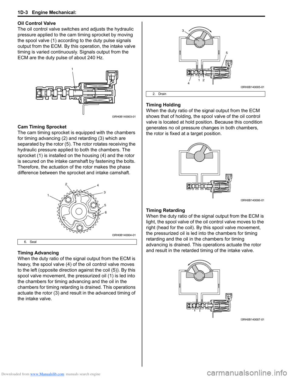
Oil Control Valve
The oil control valve switches and adjusts the hydraulic
pressure applied to the cam timing sprocket by moving
the spool valve (1) according to the duty pulse signals
output from the ECM. By this operation, the intake valve
timing is varied continuously. Signals output from the
ECM are the duty pulse of about 240 Hz.
Cam Timing Sprocket
The cam timing sprocket is equipped with the chambers
for timing advancing (2) and retarding (3) which are
separated by the rotor (5). The rotor rotates receiving the
hydraulic pressure applied to both the chambers. The
sprocket (1) is installed on the housing (4) and the rotor
is secured on the intake camshaft by fastening the bolts.
Therefore, the actuation of the rotor makes the phase
difference between the sprocket and intake camshaft.
Timing Advancing
When the duty ratio of the signal output from the ECM is
heavy, the spool valve (4) of the oil control valve moves
to the left (opposite direction against the coil (5)). By this
spool valve movement, the pressurized oil (1) is led into
the chambers for timing advancing and the oil in the
chambers for timing retarding is drained. This operations
actuate the rotor (3) and result in the advanced timing of
the intake valve. Timing Holding
When the duty ratio of the si
gnal output from the ECM
shows that of holding, the sp ool valve of the oil control
valve is located at hold posi tion. Because this condition
generates no oil pressure changes in both chambers,
the rotor is fixed at a target position.
Timing Retarding
When the duty ratio of the sig nal output from the ECM is
light, the spool valve of the o il control valve moves to the
right (head for the coil). By this spool valve movement,
the pressurized oil is led into the chambers for timing
retarding and the oil in the chambers for timing
advancing is drained. This operations actuate the rotor
and result in the retarded timing of the intake valve.
6. Seal
1
I3RH0B140003-01
1 2
3
4
56
I3RH0B140004-01
2. Drain
12
5
4
3
I3RH0B140005-01
I3RH0B140006-01
I3RH0B140007-01
Page 313 of 1496

Downloaded from www.Manualslib.com manuals search engine Engine Mechanical: 1D-28
Crankshaft Timing Sprocket
Check teeth of sprocket for wear or damage.Timing Chain
Check timing chain for wear or damage.
Timing Chain Tensioner Adjuster
Check that tooth surface (1) are free from damage.
Camshaft, Tappet and Shim ComponentsS7RS0B1406020
I2RH0B140070-01
I2RH01140077-01
I2RH0B140071-01
I6RS0C140018-01
1. Intake camshaft
5. Shim
: Shim No. on it faces tappet side. 9. Camshaft bearing
: Install a bearing half with some holes to upper side of intake
camshaft No.1 bearing.
2. Intake camshaft sprocket assembly 6. Tappet : 60 N⋅m (6.0 kgf-m, 43.5 lb-ft)
3. Intake camshaft sprocket bolt 7. Camshaft housing : Tighten 5 N⋅m (0.5 kgf-m, 4.0 lb-ft) and 11 N ⋅m (1.1 kgf-m,
8.0 lb-ft) by the specified procedure.
4. Exhaust camshaft 8. Camshaft housing bolt : Apply engine oil to sliding surface of each part.
Page 315 of 1496

Downloaded from www.Manualslib.com manuals search engine Engine Mechanical: 1D-30
Installation1) Install tappets and shims to cylinder head. Apply engine oil around tappet and then install it to
cylinder head.
NOTE
When installing shim, make sure to direct
shim No. side toward tappet.
2) Install camshaft bearing (1) to cylinder head.
CAUTION!
Do not apply engine oil to camshaft bearing
back.
Only a upper half bearing of intake camshaft
bearing No.1 has some holes. Other
bearings.
3) Install intake camshaft (1) and exhaust camshaft (2). Align knock pin (3) and match mark (4) with notches
(5) as shown in figure.
NOTE
Before installing camshafts, turn crankshaft
until key position faces upward.
Refer to “Timing Chain and Chain Tensioner
Removal and Installation”.
4) Apply engine oil to sliding surface of each camshaft and camshaft journal then install them as shown in
figure.
5) Install camshaft housing pins (1) as shown in figure.
6) Check position of camshaft housings. Embossed marks are provided on each camshaft
housing, indicating position and direction for
installation. Install housings as indicated by these
marks.I2RH0B140075-01
1
I3RH0B140039-01
“a”: Approx. 30 °
A: I: Intake side or E: Exhaust side
B: Position from timing chain side
C: Pointing to timing chain side
1 2
3 4
5
“a”
I6RS0C140019-01
I3RM0A140033-01
I2RH0B140078-01
Page 316 of 1496
Downloaded from www.Manualslib.com manuals search engine 1D-31 Engine Mechanical:
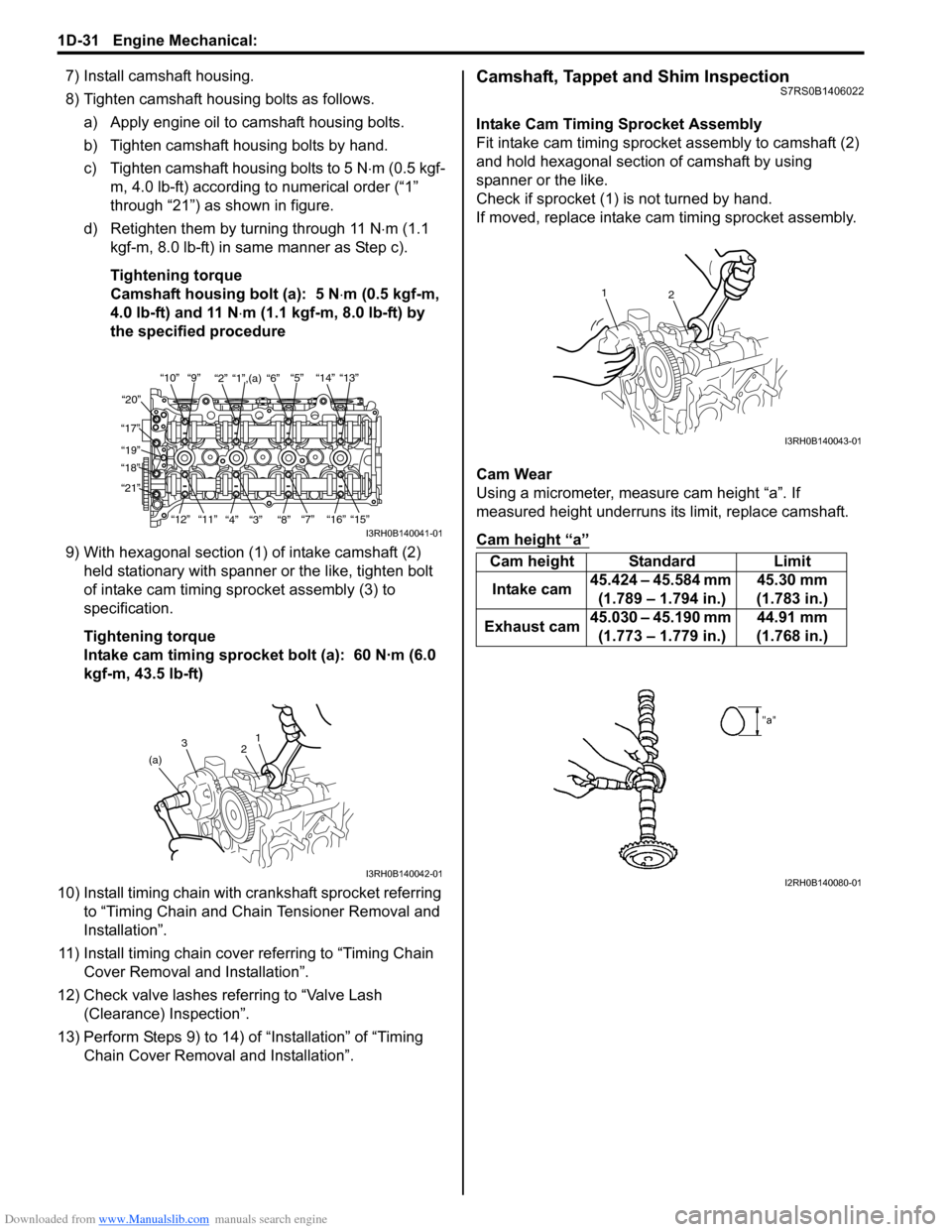
7) Install camshaft housing.
8) Tighten camshaft housing bolts as follows.a) Apply engine oil to camshaft housing bolts.
b) Tighten camshaft housing bolts by hand.
c) Tighten camshaft housing bolts to 5 N ⋅m (0.5 kgf-
m, 4.0 lb-ft) according to numerical order (“1”
through “21”) as shown in figure.
d) Retighten them by turning through 11 N⋅ m (1.1
kgf-m, 8.0 lb-ft) in same manner as Step c).
Tightening torque
Camshaft housing bolt (a): 5 N ⋅m (0.5 kgf-m,
4.0 lb-ft) and 11 N ⋅m (1.1 kgf-m, 8.0 lb-ft) by
the specified procedure
9) With hexagonal section (1) of intake camshaft (2) held stationary with spanner or the like, tighten bolt
of intake cam timing sp rocket assembly (3) to
specification.
Tightening torque
Intake cam timing sprocket bolt (a): 60 N·m (6.0
kgf-m, 43.5 lb-ft)
10) Install timing chain with cr ankshaft sprocket referring
to “Timing Chain and Chain Tensioner Removal and
Installation”.
11) Install timing chain cover referring to “Timing Chain Cover Removal and Installation”.
12) Check valve lashes referring to “Valve Lash (Clearance) Inspection”.
13) Perform Steps 9) to 14) of “Installation” of “Timing Chain Cover Removal and Installation”.Camshaft, Tappet and Shim InspectionS7RS0B1406022
Intake Cam Timing Sprocket Assembly
Fit intake cam timing sprocket assembly to camshaft (2)
and hold hexagonal section of camshaft by using
spanner or the like.
Check if sprocket (1) is not turned by hand.
If moved, replace intake ca m timing sprocket assembly.
Cam Wear
Using a micrometer, measure cam height “a”. If
measured height underruns its limit, replace camshaft.
Cam height “a”
“10”“9” “2” “1”,(a) “6” “5” “14” “13”
“20”
“17” “19”
“18”
“21”
“12”“11”
“4” “3” “8” “7” “16” “15”
I3RH0B140041-01
1
2
3
(a)
I3RH0B140042-01
Cam height Standard Limit
Intake cam 45.424 – 45.584 mm
(1.789 – 1.794 in.) 45.30 mm
(1.783 in.)
Exhaust cam 45.030 – 45.190 mm
(1.773 – 1.779 in.) 44.91 mm
(1.768 in.)
2
1
I3RH0B140043-01
I2RH0B140080-01
Page 317 of 1496
Downloaded from www.Manualslib.com manuals search engine Engine Mechanical: 1D-32
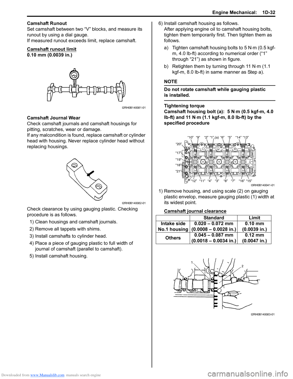
Camshaft Runout
Set camshaft between two “V” blocks, and measure its
runout by using a dial gauge.
If measured runout exceeds limit, replace camshaft.
Camshaft runout limit
0.10 mm (0.0039 in.)
Camshaft Journal Wear
Check camshaft journals and camshaft housings for
pitting, scratches, wear or damage.
If any malcondition is found, replace camshaft or cylinder
head with housing. Never re place cylinder head without
replacing housings.
Check clearance by using ga uging plastic. Checking
procedure is as follows.
1) Clean housings and camshaft journals.
2) Remove all tappets with shims.
3) Install camshafts to cylinder head.
4) Place a piece of gauging plastic to full width of
journal of camshaft (parallel to camshaft).
5) Install camshaft housing. 6) Install camshaft housing as follows.
After applying engine oil to camshaft housing bolts,
tighten them temporarily first. Then tighten them as
follows.
a) Tighten camshaft housing bolts to 5 N ⋅m (0.5 kgf-
m, 4.0 lb-ft) according to numerical order (“1”
through “21”) as shown in figure.
b) Retighten them by turning through 11 N ⋅m (1.1
kgf-m, 8.0 lb-ft) in same manner as Step a).
NOTE
Do not rotate camshaft while gauging plastic
is installed.
Tightening torque
Camshaft housing bolt (a): 5 N ⋅m (0.5 kgf-m, 4.0
lb-ft) and 11 N ⋅m (1.1 kgf-m, 8.0 lb-ft) by the
specified procedure
1) Remove housing, and using scale (2) on gauging plastic envelop, measure gauging plastic (1) width at
its widest point.
Camshaft journal clearanceI2RH0B140081-01
I2RH0B140082-01
Standard Limit
Intake side
No.1 housing 0.020 – 0.072 mm
(0.0008 – 0.0028 in.) 0.10 mm
(0.0039 in.)
Others 0.045 – 0.087 mm
(0.0018 – 0.0034 in.) 0.12 mm
(0.0047 in.)
“10”“9” “2” “1”,(a) “6” “5” “14” “13”
“20”
“17” “19”
“18”
“21”
“12”“11”
“4” “3” “8” “7” “16” “15”
I3RH0B140041-01
I2RH0B140083-01
Page 338 of 1496
Downloaded from www.Manualslib.com manuals search engine 1D-53 Engine Mechanical:
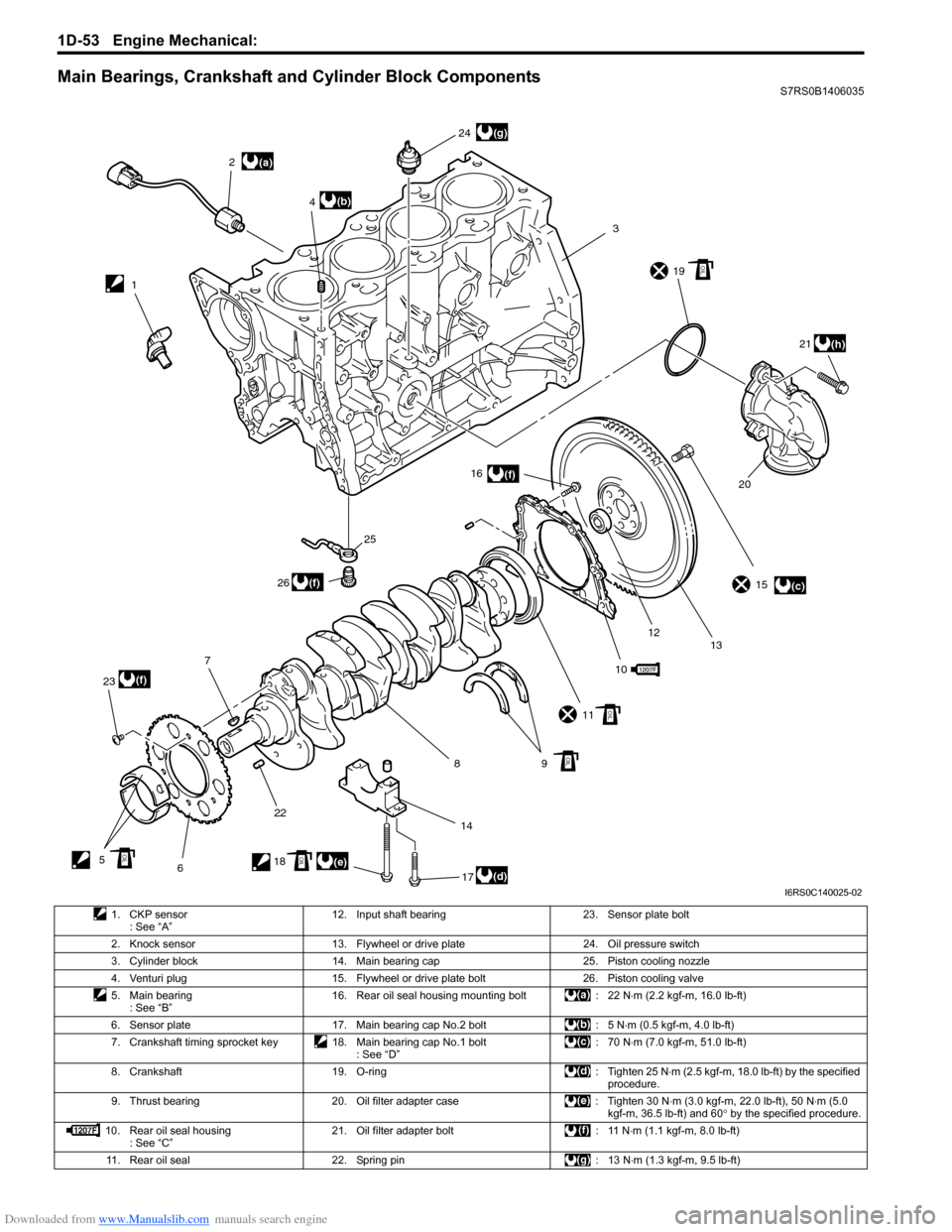
Main Bearings, Crankshaft and Cylinder Block ComponentsS7RS0B1406035
(a)
(c)
(d)(e)
(b)
(f)
(f)
(f)
(g)
(h)
12
3
4
5 67
8910
11 15
12 13
14 16
17
18 19
2021
22
23 24
25
26
OIL
OIL
OIL
OILOIL
I6RS0C140025-02
1. CKP sensor : See “A” 12. Input shaft bearing 23. Sensor plate bolt
2. Knock sensor 13. Flywheel or drive plate 24. Oil pressure switch 3. Cylinder block 14. Main bearing cap 25. Piston cooling nozzle
4. Venturi plug 15. Flywheel or drive plate bolt 26. Piston cooling valve
5. Main bearing : See “B” 16. Rear oil seal housing mounting bolt : 22 N
⋅m (2.2 kgf-m, 16.0 lb-ft)
6. Sensor plate 17. Main bearing cap No.2 bolt : 5 N ⋅m (0.5 kgf-m, 4.0 lb-ft)
7. Crankshaft timing sprocket key 18. Main bearing cap No.1 bolt : See “D”:70 N
⋅m (7.0 kgf-m, 51.0 lb-ft)
8. Crankshaft 19. O-ring : Tighten 25 N ⋅m (2.5 kgf-m, 18.0 lb-ft) by the specified
procedure.
9. Thrust bearing 20. Oil filter adapter case : Tighten 30 N ⋅m (3.0 kgf-m, 22.0 lb-ft), 50 N⋅m (5.0
kgf-m, 36.5 lb-ft) and 60 ° by the specified procedure.
10. Rear oil seal housing : See “C” 21. Oil filter adapter bolt : 11 N
⋅m (1.1 kgf-m, 8.0 lb-ft)
11. Rear oil seal 22. Spring pin : 13 N ⋅m (1.3 kgf-m, 9.5 lb-ft)
Page 339 of 1496
Downloaded from www.Manualslib.com manuals search engine Engine Mechanical: 1D-54
Main Bearings, Crankshaft and Cylinder Block
Removal and Installation
S7RS0B1406036
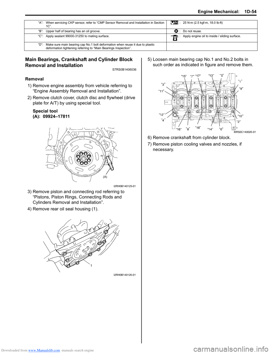
Removal1) Remove engine assembly from vehicle referring to “Engine Assembly Removal and Installation”.
2) Remove clutch cover, clut ch disc and flywheel (drive
plate for A/T) by using special tool.
Special tool
(A): 09924–17811
3) Remove piston and connecting rod referring to “Pistons, Piston Rings, Connecting Rods and
Cylinders Removal and Installation”.
4) Remove rear oil seal housing (1). 5) Loosen main bearing cap No.1 and No.2 bolts in
such order as indicated in figure and remove them.
6) Remove crankshaft from cylinder block.
7) Remove piston cooling valves and nozzles, if necessary.
“A”: When servicing CKP sensor, refer to “CMP Sensor Removal and Installation in Section 1C”. :25 N
⋅m (2.5 kgf-m, 18.0 lb-ft)
“B”: Upper half of bearing has an oil groove. : Do not reuse.
“C”: Apply sealant 99000-31250 to mating surface. : Apply engine oil to inside / sliding surface.
“D”: Make sure main bearing cap No.1 bolt deformation when reuse it due to plastic deformation tightening referring to “Main Bearings Inspection”.
I2RH0B140125-01
I2RH0B140126-01
I6RS0C140026-01
Page 341 of 1496
Downloaded from www.Manualslib.com manuals search engine Engine Mechanical: 1D-56
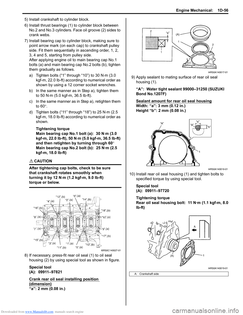
5) Install crankshaft to cylinder block.
6) Install thrust bearings (1) to cylinder block between No.2 and No.3 cylinders. Face oil groove (2) sides to
crank webs.
7) Install bearing cap to cylinder block, making sure to point arrow mark (on each cap) to crankshaft pulley
side. Fit them sequentially in ascending order, 1, 2,
3, 4 and 5, starting from pulley side.
After applying engine oil to main bearing cap No.1
bolts (a) and main bearing cap No.2 bolts (b), tighten
them gradually as follows.
a) Tighten bolts (“1” through “10”) to 30 N ⋅m (3.0
kgf-m, 22.0 lb-ft) according to numerical order as
shown by using a 12 corner socket wrenches.
b) In the same manner as in Step a), tighten them to 50 N ⋅m (5.0 kgf-m, 36.5 lb-ft).
c) In the same manner as in Step a), retighten them to 60 °.
d) Tighten bolts (“11” through “18”) to 25 N ⋅m (2.5
kgf-m, 18.0 lb-ft) according to numerical order as
shown.
Tightening torque
Main bearing cap No.1 bolt (a): 30 N ⋅m (3.0
kgf-m, 22.0 lb-ft), 50 N ⋅m (5.0 kgf-m, 36.5 lb-ft)
and then retighten by turning through 60 °
Main bearing cap No.2 bolt (b): 25 N·m (2.5
kgf-m, 18.0 lb-ft)
CAUTION!
After tightening cap bolts, check to be sure
that crankshaft rotates smoothly when
turning it by 12 N ⋅m (1.2 kgf-m, 9.0 lb-ft)
torque or below.
8) If necessary, press-fit rear oil seal (1) to oil seal housing (2) by using special tool as shown in figure.
Special tool
(A): 09911–97821
Crank rear oil seal installing position
(dimension)
“a”: 2 mm (0.08 in.) 9) Apply sealant to mating surface of rear oil seal
housing (1).
“A”: Water tight sealant 99000–31250 (SUZUKI
Bond No.1207F)
Sealant amount for rear oil seal housing
Width: “a”: 3 mm (0.12 in.)
Height “b”: 2 mm (0.08 in.)
10) Install rear oil seal housing (1) and tighten bolts to specified torque by using special tool.
Special tool
(A): 09911–97720
Tightening torque
Rear oil seal housing bolt: 11 N·m (1.1 kgf-m, 8.0
lb-ft)
I6RS0C140027-01
A: Crankshaft side
I4RS0A140017-01
I4RS0A140018-01
I4RS0A140019-01