2008 SUZUKI SWIFT Oil housing
[x] Cancel search: Oil housingPage 753 of 1496

Downloaded from www.Manualslib.com manuals search engine A u to m a tic Tra n s m is s io n /Tra n s a x le : 5 A -1 0 9
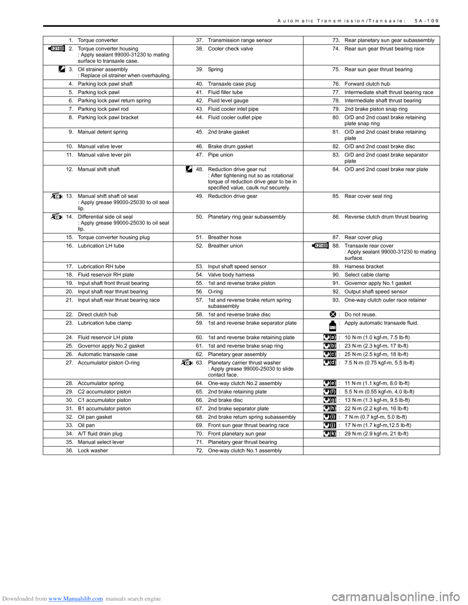
1. Torque converter37. Transmission range sensor 73. Rear planetary sun gear subassembly
2. Torque converter housing : Apply sealant 99000-31230 to mating
surface to transaxle case. 38. Cooler check valve
74. Rear sun gear thrust bearing race
3. Oil strainer assembly : Replace oil strainer when overhauling. 39. Spring
75. Rear sun gear thrust bearing
4. Parking lock pawl shaft 40. Transaxle case plug 76. Forward clutch hub
5. Parking lock pawl 41. Fluid filler tube 77. Intermediate shaft thrust bearing race
6. Parking lock pawl return spring 42. Fluid level gauge 78. Intermediate shaft thrust bearing
7. Parking lock pawl rod 43. Fluid cooler inlet pipe 79. 2nd brake piston snap ring
8. Parking lock pawl bracket 44. Fluid cooler outlet pipe 80. O/D and 2nd coast brake retaining
plate snap ring
9. Manual detent spring 45. 2nd brake gasket 81. O/D and 2nd coast brake retaining
plate
10. Manual valve lever 46. Brake drum gasket 82. O/D and 2nd coast brake disc
11. Manual valve lever pin 47. Pipe union 83. O/D and 2nd coast brake separator
plate
12. Manual shift shaft 48. Reduction drive gear nut
: After tightening nut so as rotational
torque of reduction drive gear to be in
specified value, caulk nut securely. 84. O/D and 2nd coast brake rear plate
13. Manual shift shaft oil seal : Apply grease 99000-25030 to oil seal
lip. 49. Reduction drive gear
85. Rear cover seal ring
14. Differential side oil seal : Apply grease 99000-25030 to oil seal
lip. 50. Planetary ring gear subassembly
86. Reverse clutch drum thrust bearing
15. Torque converter housing plug 51. Breather hose 87. Rear cover plug
16. Lubrication LH tube 52. Breather union 88. Transaxle rear cover
: Apply sealant 99000-31230 to mating
surface.
17. Lubrication RH tube 53. Input shaft speed sensor 89. Harness bracket
18. Fluid reservoir RH plate 54. Valve body harness 90. Select cable clamp
19. Input shaft front thrust bearing 55. 1st and reverse brake piston 91. Governor apply No.1 gasket
20. Input shaft rear thrust bearing 56. O-ring 92. Output shaft speed sensor
21. Input shaft rear thrust bearing race 57. 1st and reverse brake return spring
subassembly 93. One-way clutch outer race retainer
22. Direct clutch hub 58. 1st and reverse brake disc : Do not reuse.
23. Lubrication tube clamp 59. 1st and reverse brake separator plate : Apply automatic transaxle fluid.
24. Fluid reservoir LH plate 60. 1st and reverse brake retaining plate : 10 N⋅m (1.0 kgf-m, 7.5 lb-ft)
25. Governor apply No.2 gasket 61. 1st and reverse brake snap ring : 23 N⋅m (2.3 kgf-m, 17 lb-ft)
26. Automatic transaxle case 62. Planetary gear assembly : 25 N⋅m (2.5 kgf-m, 18 lb-ft)
27. Accumulator piston O-ring 63. Planetary carrier thrust washer
: Apply grease 99000-25030 to slide
contact face. : 7.5 N
⋅m (0.75 kgf-m, 5.5 lb-ft)
28. Accumulator spring 64. One-way clutch No.2 assembly : 11 N⋅m (1.1 kgf-m, 8.0 lb-ft)
29. C2 accumulator piston 65. 2nd brake retaining plate : 5.5 N⋅m (0.55 kgf-m, 4.0 lb-ft)
30. C1 accumulator piston 66. 2nd brake disc : 13 N⋅m (1.3 kgf-m, 9.5 lb-ft)
31. B1 accumulator piston 67. 2nd brake separator plate : 22 N⋅m (2.2 kgf-m, 16 lb-ft)
32. Oil pan gasket 68. 2nd brake return spring subassembly : 7 N⋅m (0.7 kgf-m, 5.0 lb-ft)
33. Oil pan 69. Front sun gear thrust bearing race : 17 N⋅m (1.7 kgf-m,12.5 lb-ft)
34. A/T fluid drain plug 70. Front planetary sun gear : 29 N⋅m (2.9 kgf-m, 21 lb-ft)
35. Manual select lever 71. Planetary gear thrust bearing
36. Lock washer 72. One-way clutch No.1 assembly
Page 757 of 1496

Downloaded from www.Manualslib.com manuals search engine Automatic Transmission/Transaxle: 5A-113
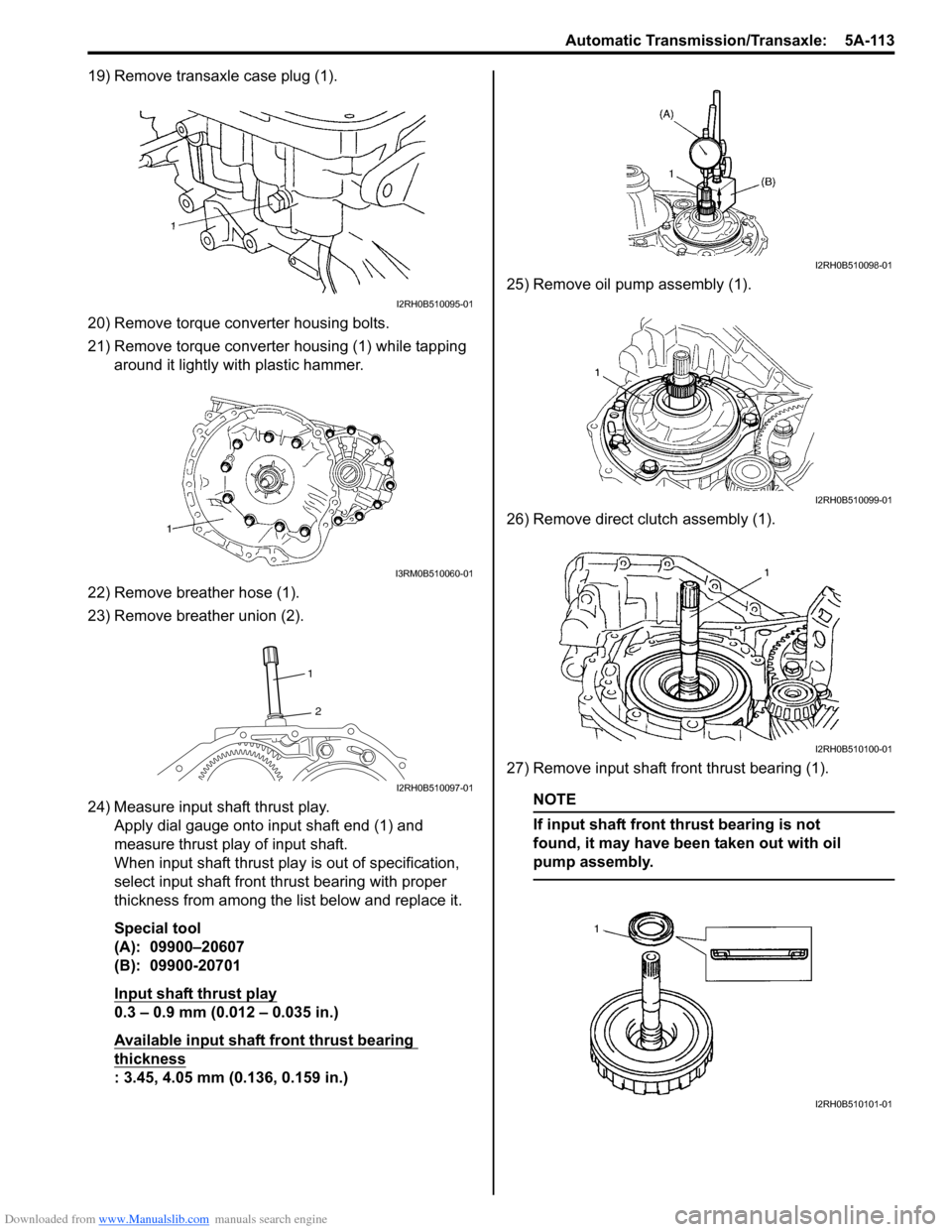
19) Remove transaxle case plug (1).
20) Remove torque converter housing bolts.
21) Remove torque converter housing (1) while tapping
around it lightly with plastic hammer.
22) Remove breather hose (1).
23) Remove breather union (2).
24) Measure input shaft thrust play. Apply dial gauge onto input shaft end (1) and
measure thrust play of input shaft.
When input shaft thrust play is out of specification,
select input shaft front th rust bearing with proper
thickness from among the list below and replace it.
Special tool
(A): 09900–20607
(B): 09900-20701
Input shaft thrust play
0.3 – 0.9 mm (0.012 – 0.035 in.)
Available input shaft front thrust bearing
thickness
: 3.45, 4.05 mm (0.136, 0.159 in.) 25) Remove oil pump assembly (1).
26) Remove direct clutch assembly (1).
27) Remove input shaft front thrust bearing (1).
NOTE
If input shaft front thrust bearing is not
found, it may have been taken out with oil
pump assembly.
I2RH0B510095-01
I3RM0B510060-01
1
2
I2RH0B510097-01
I2RH0B510098-01
I2RH0B510099-01
I2RH0B510100-01
I2RH0B510101-01
Page 788 of 1496

Downloaded from www.Manualslib.com manuals search engine 5A-144 Automatic Transmission/Transaxle:
Torque Converter Housing Disassembly and
Reassembly
S7RS0B5106057
Disassembly1) Remove fluid reservoir RH plate (1) and lubrication tube clamp (2).
2) Remove lubrication LH tube (1) and RH tube (2).
NOTE
Do not bend lubrication tube with excessive
force.
3) Remove differential side oil seal (1). 4) Remove countershaft RH bearing cup by using
special tools.
Special tool
(A): 09944–96011
(B): 09942–15511
5) Remove differential side RH bearing cup by using special tools.
Special tool
(A): 09944–96011
(B): 09942–15511
6) Remove torque converter case plugs (1).
I2RH0B510236-01
I2RH0B510237-01
I2RH0B510238-01
I2RH0B510239-01
I2RH0B510240-01
I2RH0B510241-01
Page 789 of 1496

Downloaded from www.Manualslib.com manuals search engine Automatic Transmission/Transaxle: 5A-145
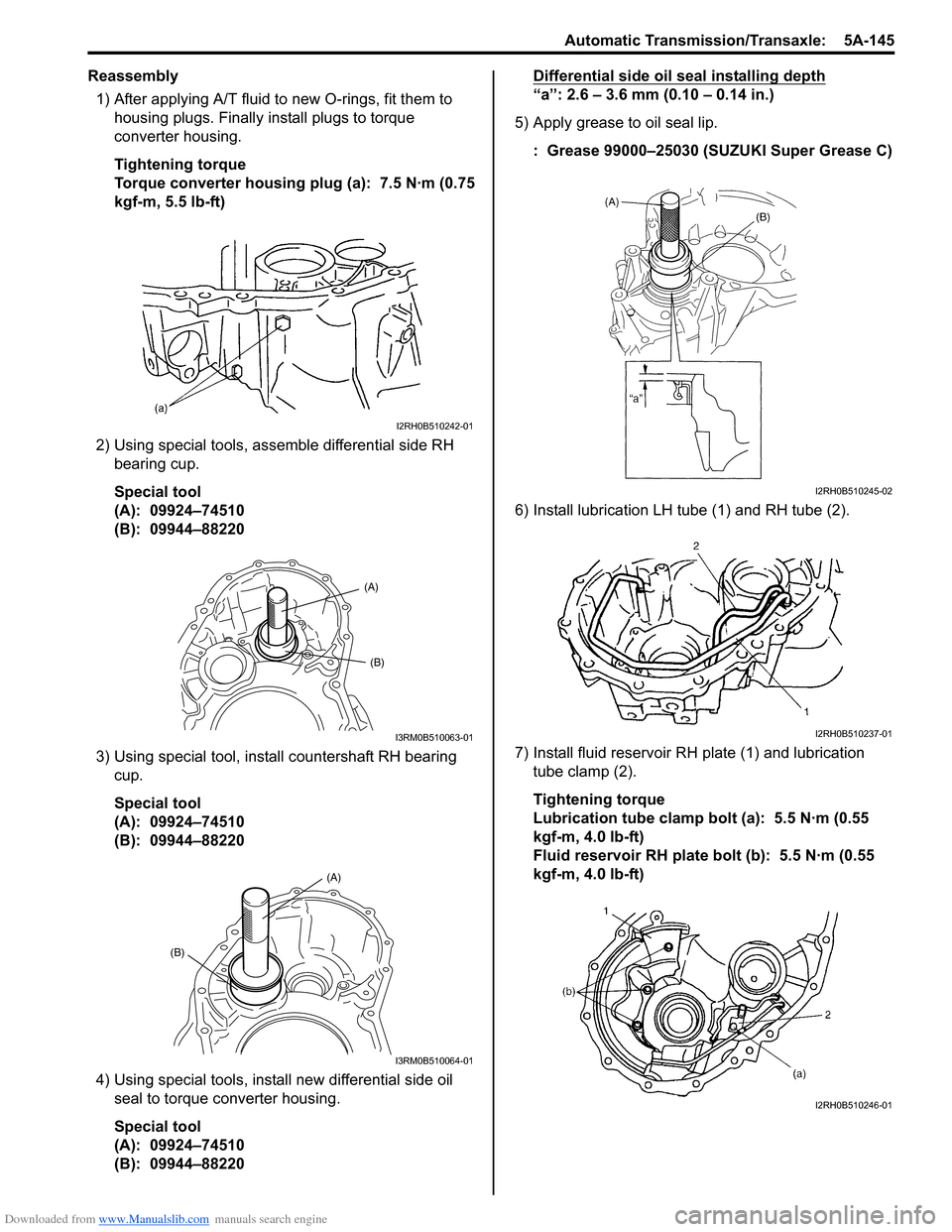
Reassembly1) After applying A/T fluid to new O-rings, fit them to housing plugs. Finally install plugs to torque
converter housing.
Tightening torque
Torque converter housing plug (a): 7.5 N·m (0.75
kgf-m, 5.5 lb-ft)
2) Using special tools, assemble differential side RH bearing cup.
Special tool
(A): 09924–74510
(B): 09944–88220
3) Using special tool, install countershaft RH bearing cup.
Special tool
(A): 09924–74510
(B): 09944–88220
4) Using special tools, install new differential side oil seal to torque converter housing.
Special tool
(A): 09924–74510
(B): 09944–88220 Differential side oil seal installing depth
“a”: 2.6 – 3.6 mm (0.10 – 0.14 in.)
5) Apply grease to oil seal lip. : Grease 99000–25030 (SUZUKI Super Grease C)
6) Install lubrication LH tube (1) and RH tube (2).
7) Install fluid reservoir RH plate (1) and lubrication tube clamp (2).
Tightening torque
Lubrication tube clamp bolt (a): 5.5 N·m (0.55
kgf-m, 4.0 lb-ft)
Fluid reservoir RH plate bolt (b): 5.5 N·m (0.55
kgf-m, 4.0 lb-ft)
I2RH0B510242-01
(A)
(B)
I3RM0B510063-01
(B) (A)
I3RM0B510064-01
I2RH0B510245-02
I2RH0B510237-01
I2RH0B510246-01
Page 810 of 1496

Downloaded from www.Manualslib.com manuals search engine 5A-166 Automatic Transmission/Transaxle:
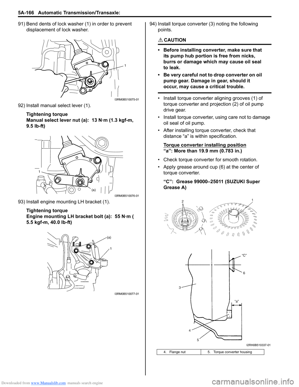
91) Bend dents of lock washer (1) in order to prevent displacement of lock washer.
92) Install manual select lever (1). Tightening torque
Manual select lever nut (a): 13 N·m (1.3 kgf-m,
9.5 lb-ft)
93) Install engine mounting LH bracket (1). Tightening torque
Engine mounting LH bracket bolt (a): 55 N·m (
5.5 kgf-m, 40.0 lb-ft) 94) Install torque converter (3) noting the following
points.
CAUTION!
• Before installing converter, make sure that its pump hub portion is free from nicks,
burrs or damage which may cause oil seal
to leak.
• Be very careful not to drop converter on oil pump gear. Damage in gear, should it
occur, may cause a critical trouble.
• Install torque converter aligning grooves (1) of torque converter and projection (2) of oil pump
drive gear.
• Install torque converter, using care not to damage oil seal of oil pump.
• After installing torque converter, check that distance “a” is within specification.
Torque converter installing position
“a”: More than 19.9 mm (0.783 in.)
• Check torque converter for smooth rotation.
• Apply grease around cup (6) at the center of torque converter.
“C”: Grease 99000–25011 (SUZUKI Super
Grease A)
1
I3RM0B510075-01
1
(a)
I3RM0B510076-01
I3RM0B510077-01
4. Flange nut 5. Torque converter housing
I2RH0B510337-01
Page 811 of 1496

Downloaded from www.Manualslib.com manuals search engine Automatic Transmission/Transaxle: 5A-167
Specifications
Tightening Torque SpecificationsS7RS0B5107001
NOTE
The specified tightening torque is also described in the following.
“Select Cable Components”
“Automatic Transaxle Unit Components”
“Automatic Transaxle Assembly Components”
“Oil Pump Assembly Components”
“Transaxle Rear Cover (O/D and 2nd Coast Brake Piston) Assembly Components”
“Valve Body Assembly Components”
“Differential Assembly Components”
Reference:
For the tightening torque of fastener not specified in this section, refer to “Fasteners Information in Section 0A”.
Fastening part
Tightening torque
Note
N ⋅mkgf-mlb-ft
A/T fluid drain plug 171.7 12.5 �) / �) / �)
Transmission range sensor bolt 5.5 0.55 4.0�) / �)
Output shaft speed sensor bolt 131.3 9.5 �) / �)
Input shaft speed sensor bolt 5.5 0.55 4.0�)
Valve body harness connector bolt 7.00.7 5.0 �)
Shift solenoid bolt 111.1 8.0 �)
Oil strainer bolt 101.0 7.5 �) / �)
Oil pan bolt 7.00.7 5.0 �) / �)
Transaxle and engine fastening bolt and nut 85 8.5 61.5�)
Drive plate to torque converter bolt 252.5 18.0 �)
Transaxle stiffener bolt 555.5 40�)
Starter motor bolt and nut 505.0 36.5 �)
Oil pump subassembly bolt 101.0 7.5 �)
Rear cover plug 7.5 0.75 5.5�)
Solenoid valve bolt 111.1 8.0 �)
Final gear bolt 787.8 56.5 �)
Torque converter housing plug 7.5 0.75 5.5�)
Lubrication tube clamp bolt 5.5 0.55 4.0�)
Fluid reservoir RH plate bolt 5.5 0.55 4.0�)
Torque converter housing bolt 292.9 21�) / �) / �)
Manual detent spring bolt 101.0 7.5 �)
Parking lock pawl bracket bolt 7.5 0.75 5.5�)
Rear cover bolt 252.5 18.0 �)
Fluid reservoir LH plate bolt 101.0 7.5 �)
Oil pump assembly bolt 252.5 18.0 �)
Transaxle case plug 7.5 0.75 5.5�)
Valve body harness connector bolt 5.5 0.55 4.0�)
Valve body bolt 111.1 8.0 �)
Fluid outlet union 252.5 18.0 �)
Fluid cooler pipe union bolt 222.2 16.0 �)
Fluid cooler pipe bracket bolt 101.0 7.5 �)
Fluid filler tube bolt 101.0 7.5 �)
Input shaft speed sensor bolt 111.1 8.0 �)
Harness bracket bolt 232.3 17.0 �)
Select cable clamp bolt 101.0 7.5 �)
Transmission range sensor lock nut 70.7 5.0 �)
Manual select lever nut 131.3 9.5 �)
Engine mounting LH bracket bolt 555.5 40.0
�)
Page 823 of 1496

Downloaded from www.Manualslib.com manuals search engine Manual Transmission/Transaxle: 5B-9
Manual Transaxle Unit Dismounting and
Remounting
S7RS0B5206009
Dismounting1) Drain coolant and transaxle oil.
2) Remove coolant reservoir with reservoir hose.
3) Remove battery and tray.
4) Remove air cleaner case and resonator.
5) Disconnect gear shift and gear select control cables (1) while pressing claws (2) of clip (3).
6) Disconnect back up light switch coupler and undo wiring harness clamps.
7) Remove ground cable from transaxle.
8) Remove clutch operating cylinder with fluid hose from transaxle.
9) Remove water inlet No.2 pipe from transaxle.
10) Remove starting motor re ferring to “Starting Motor
Dismounting and Remounting in Section 1I”.
11) Remove transaxle to engine bolts (1) of upper side. 12) Support engine using supporting device (1).
CAUTION!
Do not apply supporting device to projection
part A. If do so, it may be deformed.
13) Remove front drive shafts and center shaft referring
to “Front Drive Shaft Assembly Removal and
Installation in Section 3A”.
14) Remove exhaust No.2 pipe referring to “Exhaust Pipe and Muffler Removal a nd Installation in Section
1K”.
15) Remove clutch housing lower plate (1).
1
2
3
I7RS0A521003-01
1
1
I4RS0A520018-01
1
A
I4RS0A520019-01
1I4RS0A520020-01
Page 1168 of 1496

Downloaded from www.Manualslib.com manuals search engine 9-ii Table of Contents
List of Connectors ........................................... 9A-103
C Connector .................................................... 9A-103
D Connector (M16A engine) ........................... 9A-104
E Connector .................................................... 9A-104
G Connector .................................................... 9A-106
J Connector ..................................................... 9A-108
K Connector .................................................... 9A-109
L Connector..................................................... 9A-109
M Connector (SPORT model) ......................... 9A-111
O Connector .................................................... 9A-111
R Connector .................................................... 9A-111
Lighting Systems .................................... 9B-1
Component Location ........... ................................9B-1
Lighting System Component s Location............... 9B-1
Interior Light System Location............................. 9B-2
Diagnostic Information and Procedures ............ 9B-2 Headlight Symptom Diagnosis ............................ 9B-2
Headlight Leveling System Symptom Diagnosis (If Equipped) ..................................... 9B-2
Turn Signal and Hazard Warning Light Symptom Diagnosis .......................................... 9B-3
Clearance, Tail and License Plate Light Symptom Diagnosis .......................................... 9B-3
Back-Up Light Symptom Diagnosis..................... 9B-4
Brake Light Symptom Diagnosis ......................... 9B-4
Front Fog Light Symptom Diagnosis (If Equipped) .......................................................... 9B-4
Interior Light Symptom Diagnosis ....................... 9B-5
Repair Instructions ..............................................9B-5 Headlight Housing Removal and Installation ...... 9B-5
Headlight Bulb Replacemen t............................... 9B-6
Headlight Aiming Adjustment with Screen .......... 9B-6
Headlight Switch (in Lighting Switch) Removal and Installation ................................... 9B-8
Headlight Switch (in Lighting Switch) Inspection .......................................................... 9B-8
Hazard Warning Switch Removal and Installation ......................................................... 9B-8
Hazard Warning Switch Inspection ..................... 9B-9
Brake Light Switch Inspection ............................. 9B-9
Turn Signal Light Switch (in Lighting Switch) Removal and Installation ................................... 9B-9
Turn Signal Light Switch (in Lighting Switch) Inspection .......................................................... 9B-9
Turn Signal and Hazard Warning Relay Removal and Installation ................................... 9B-9
Turn Signal and Hazard Warning Relay Inspection ........................................................ 9B-10
License Light Removal and Installation............. 9B-10
Front Fog Light Removal and Installation (If Equipped) ........................................................ 9B-11
Front Fog Light Bulb Replacement (If Equipped) ........................................................ 9B-11
Front Fog Light Switch Inspection (If Equipped) ........................................................ 9B-11
Front Fog Light Relay Inspection (If Equipped) ........................................................ 9B-11
Front Fog Light Aiming Adjustment with Screen (If Equipped) ....................................... 9B-12 Headlight Leveling Switch Inspection (If
Equipped) ........................................................ 9B-13
Headlight Leveling Actuator Inspection (If Equipped) ........................................................ 9B-13
Instrumentation / Driver Info. / Horn ...... 9C-1
Precautions ...........................................................9C-1 Precautions in Diagnosing Troubles for Combination Meter ............................................9C-1
General Description .............................................9C-1 CAN Communication System Description...........9C-1
Auto Volume Co ntrol System Description (If
Equipped) ..........................................................9C-3
Schematic and Routing Diagram ........................9C-4 Combination Meter Circuit Diagram ....................9C-4
Component Location ............ ...............................9C-6
Audio System Component Location ....................9C-6
Diagnostic Information and Procedures ............9C-6 Speedometer and VSS Symp tom Diagnosis ......9C-6
Tachometer Symptom Diagnosis ........................9C-6
Engine Coolant Temperature (ECT) Meter Symptom Diagnosis ..........................................9C-7
Fuel Meter Symptom Diagnosis ..........................9C-7
Low Fuel Warning Light Symptom Diagnosis .....9C-7
Oil Pressure Warning Light Symptom Diagnosis ..........................................................9C-8
Brake and Parking Brake Warning Light Symptom Diagnosis ..........................................9C-8
Seat Belt Reminder Light Symptom Diagnosis (If Equipped)......................................................9C-8
A/T Shift Position Indicator Symptom Diagnosis (A/T Model).......................................9C-9
Charge Warning Light Sy mptom Diagnosis ........9C-9
Main Beam (High Beam) Indicator Symptom Diagnosis ..........................................................9C-9
Warning Buzzer Circuit Sy mptom Diagnosis ....9C-10
Cigarette Lighter Symptom Diagnosis (If Equipped) ........................................................9C-10
Horn Symptom Diagnosis .................................9C-10
Information Display Symptom Diagnosis (If Equipped) ........................................................9C-11
Clock Symptom Diagnosis (If Equipped)...........9C-12
Audio System Symptom Diagnosis (If Equipped) ........................................................9C-12
Remote Audio Control Switch Symptom Diagnosis (If Equipped) ...................................9C-13
Navigation Symptom Diagnosis (If Equipped)...9C-14
Repair Instructions ............ ................................9C-14
Ignition Switch Removal and Installation...........9C-14
Ignition Switch Inspection..................................9C-14
Combination Meter Removal and Installation ...9C-15
Fuel Level Sensor Removal and Installation .....9C-15
Fuel Level Sensor Inspection ............................9C-15
Oil Pressure Switch Remova l and Installation ..9C-15
Oil Pressure Switch Inspec tion .........................9C-16
Engine Coolant Temperature (ECT) Sensor Inspection ........................................................9C-16
Brake Fluid Level Switch Inspection .................9C-16
Parking Brake Switch Inspec tion.......................9C-16