2008 SUZUKI SWIFT Cond rod
[x] Cancel search: Cond rodPage 52 of 1496
Downloaded from www.Manualslib.com manuals search engine 1A-2 Engine General Information and Diagnosis:
• Be sure to read “Precautions for Electrical Circuit Service in Section 00” befo re inspection and observe
what is written there.
• ECM replacement: When substituting a known-good ECM, check for the
following conditions. Neglec ting this check may cause
damage to a known-good ECM.
– Resistance value of all relays, actuators is as specified respectively.
– MAP sensor, A/C refrigerant pressure sensor and TP sensor are in good condition and none of power
circuits of these sensors is shorted to ground.
• Communication of ECM, BCM, ABS/ESP ® control
module, combination meter, keyless start control
module, steering angle sensor (ESP ® model) and
TCM (A/T model), is esta blished by CAN (Controller
Area Network). (For more detail of CAN
communication for ECM, refer to “CAN
Communication System Description”). Therefore,
handle CAN communication line with care referring to
“Precaution for CAN Communication System in
Section 00”.
• Immobilizer transponder code registration after
replacing ECM
When ECM is replaced with new one or with another
one, make sure to register immobilizer transponder
code to ECM correctly according to “Procedure after
ECM Replacement in Section 10C”.Precautions of ECM Circuit InspectionS7RS0B1100003
• ECM connectors are waterproofed. Each terminal of the ECM connectors is sealed up with the grommet.
Therefore, when measuring ci rcuit voltage, resistance
and/or pulse signal at ECM connector, do not insert
the tester’s probe into th e sealed terminal at the
harness side. When measuring circuit voltage,
resistance and/or pulse signal at ECM connector,
connect the special tool to the ECM connectors. And,
insert the tester’s probe into the special tool’s
connectors at the harness side, and then measure
voltage, resistance and/or pulse signal. Or, ECM and
its circuits may be damaged by water.
• Wire colors of the special tool’s connectors are different from the ones of the ECM connectors.
However, the circuit arrangement of the special tool’s
connectors is same as the one of the ECM
connectors. Therefore, measure circuit voltage and
resistance by identifying the terminal location subject
to the measurement.
Precautions of Electric Throttle Body System
Calibration
S7RS0B1100004
After performing one of works described below, it is
necessary to re-register the completely closed throttle
valve reference position stored in memory of ECM. (For
detailed information, refer to “Description of Electric
Throttle Body System Calibration”.) For the procedure to
register such data in ECM, refer to “Electric Throttle
Body System Calibration in Section 1C”.
• To shut off backup power of ECM for such purposes of battery replacement or “DOME” fuse removal
• To erase DTCs P0122, P01 23, P0222, P0223, P2101,
P2102, P2103, P2111, P2112, P2113, P2119, P2123,
P2127, P2128, P2135 and/or P2138
• To replace ECM
• To replace throttle body and/or accelerator pedal position (APP) sensor assembly
General Description
Statement on Cleanliness and CareS7RS0B1101001
An automobile engine is a combination of many
machined, honed, polished and lapped surfaces with
tolerances that are measured in the thousands of an
millimeter (ten thous ands of an inch).
Accordingly, when any internal engine parts are
serviced, care and cleanliness are important.
It should be understood that proper cleaning and
protection of machined surfaces and friction areas is part
of the repair procedure. This is considered standard
shop practice even if not specifically stated.
• A liberal coating of engine oil should be applied to friction areas during assembly to protect and lubricate
the surfaces on initial operation. • Whenever valve train components, pistons, piston
rings, connecting rods, rod bearings, and crankshaft
journal bearings are removed for service, they should
be retained in order.
At the time of installation, they should be installed in
the same locations and with the same mating
surfaces as when removed.
• Battery cables should be disconnected before any major work is performed on the engine.
Failure to disconnect cables may result in damage to
wire harness or other electrical parts.
Page 92 of 1496

Downloaded from www.Manualslib.com manuals search engine 1A-42 Engine General Information and Diagnosis:
Engine noise – Piston,
ring and cylinder noise
NOTE
Before checking
mechanical noise, make
sure that:
• Specified spark plug is used.
• Specified fuel is used.
Worn piston, ring and cylinder bore “Cylinders, Pistons and Piston Rings
Inspection in Section 1D”
Engine noise –
Connecting rod noise
NOTE
Before checking
mechanical noise, make
sure that:
• Specified spark plug is used.
• Specified fuel is used.
Worn piston, ring and cylinder bore “Cylinders, Pistons and Piston Rings
Inspection in Section 1D”
Worn rod bearing “Crank Pin and Connecting Rod Bearings
Inspection in Section 1D”
Worn crank pin “Crank Pin and Connecting Rod Bearings
Inspection in Section 1D”
Loose connecting rod nuts “Pistons, Piston Rings, Connecting Rods and
Cylinders Removal and Installation in Section
1D”
Low oil pressure Condition “Low oil pressure”
Engine noise –
Crankshaft noise
NOTE
Before checking
mechanical noise, make
sure that:
• Specified spark plug is used.
• Specified fuel is used.
Low oil pressure Condition “Low oil pressure”
Worn bearing “Main Bearings Inspection in Section 1D”
Worn crankshaft journal “Crankshaft Inspection in Section 1D”
Loose bearing cap bolts “Main Bearings, Crankshaft and Cylinder Block
Removal and Installation in Section 1D”
Excessive crankshaft thrust play “Crankshaft Inspection in Section 1D”
Engine overheating Inoperative thermostat “Thermostat Inspection in Section 1F”
Poor water pump performance “Water Pump Inspection in Section 1F”
Clogged or leaky radiator “Radiator On-Vehicle Inspection and Cleaning
in Section 1F”
Improper engine oil grade “Engine Oil and Filter Change in Section 0B”
Clogged oil filter or oil strainer “Oil Pressure Check in Section 1E”
Poor oil pump performance “Oil Pressure Check in Section 1E”
Faulty radiator cooling fan control
system “Radiator Cooling Fan Low Speed Control
System Check” or “Rad
iator Cooling Fan High
Speed Control System Check”
Dragging brakes Condition “Dragging brakes” in “Brakes
Symptom Diagnosis in Section 4A”
Slipping clutch Condition “Slipping clutch” in “Clutch System
Symptom Diagnosis in Section 5C”
Blown cylinder head gasket “Cylinder Head Inspection in Section 1D”
Air mixed in cooling system
Condition Possible cause Correction / Reference Item
Page 93 of 1496
Downloaded from www.Manualslib.com manuals search engine Engine General Information and Diagnosis: 1A-43
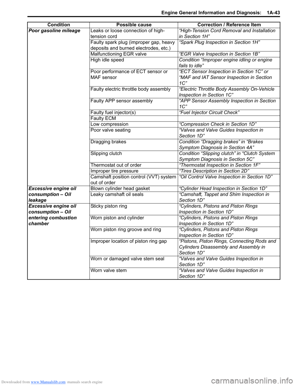
Poor gasoline mileageLeaks or loose connection of high-
tension cord “High-Tension Cord Removal and Installation
in Section 1H”
Faulty spark plug (improper gap, heavy
deposits and burned electrodes, etc.) “Spark Plug Inspection in Section 1H”
Malfunctioning EGR valve “EGR Valve Inspection in Section 1B”
High idle speed Condition “Improper engine idling or engine
fails to idle”
Poor performance of ECT sensor or
MAF sensor “ECT Sensor Inspection in Section 1C” or
“MAF and IAT Sensor Inspection in Section
1C”
Faulty electric throttle body assembly “Electric Throttle Body Assembly On-Vehicle
Inspection in Section 1C”
Faulty APP sensor assembly “APP Sensor Assembly Inspection in Section
1C”
Faulty fuel injector(s) “Fuel Injector Circuit Check”
Faulty ECM
Low compression “Compression Check in Section 1D”
Poor valve seating “Valves and Valve Guides Inspection in
Section 1D”
Dragging brakes Condition “Dragging brakes” in “Brakes
Symptom Diagnosis in Section 4A”
Slipping clutch Condition “Slipping clutch” in “Clutch System
Symptom Diagnosis in Section 5C”
Thermostat out of order “Thermostat Inspection in Section 1F”
Improper tire pressure “Tires Description in Section 2D”
Camshaft position control (VVT) system
out of order “Oil Control Valve Inspection in Section 1D”
Excessive engine oil
consumption – Oil
leakage Blown cylinder head gasket
“Cylinder Head Inspection in Section 1D”
Leaky camshaft oil seals “Camshaft, Tappet and Shim Inspection in
Section 1D”
Excessive engine oil
consumption – Oil
entering combustion
chamber Sticky piston ring
“Cylinders, Pistons and Piston Rings
Inspection in Section 1D”
Worn piston and cylinder “Cylinders, Pistons and Piston Rings
Inspection in Section 1D”
Worn piston ring groove and ring “Cylinders, Pistons and Piston Rings
Inspection in Section 1D”
Improper location of piston ring gap “Pistons, Piston Rings, Connecting Rods and
Cylinders Disassembly and Assembly in
Section 1D”
Worn or damaged valve stem seal “Valves and Valve Guides Inspection in
Section 1D”
Worn valve stem “Valves and Valve Guides Inspection in
Section 1D”
Condition Possible cause Correction / Reference Item
Page 94 of 1496

Downloaded from www.Manualslib.com manuals search engine 1A-44 Engine General Information and Diagnosis:
Engine hesitates –
Momentary lack of
response as accelerator
is depressed. Can occur
at all vehicle speeds.
Usually most severe when
first trying to make
vehicle move, as from a
stop sign.Spark plug faulty
“Spark Plug Inspection in Section 1H”
Leaky high-tension cord “High-Tension Cord Inspection in Section 1H”
Fuel pressure out of specification “Fuel Pressure Check”
Malfunctioning EGR valve “EGR Valve Inspection in Section 1B”
Poor performance of ECT sensor or
MAF sensor “ECT Sensor Inspection in Section 1C” or
“MAF and IAT Sensor Inspection in Section
1C”
Faulty electric throttle body assembly “Electric Throttle Body Assembly On-Vehicle
Inspection in Section 1C”
Faulty APP sensor assembly “APP Sensor Assembly Inspection in Section
1C”
Faulty fuel injector “Fuel Injector Circuit Check”
Faulty ECM
Engine overheating Condition “Engine overheating”
Low compression “Compression Check in Section 1D”
Camshaft position control (VVT) system
out of order “Oil Control Valve Inspection in Section 1D”
Surge – Engine power
variation under steady
throttle or cruise. Feels
like vehicle speeds up
and down with no change
in accelerator pedal. Leaky or loosely connected high-tension
cord
“High-Tension Cord Removal and Installation
in Section 1H”
Faulty spark plug (excess carbon
deposits, improper gap, burned
electrodes, etc.) “Spark Plug Inspection in Section 1H”
Variable fuel pressure “Fuel Pressure Check”
Kinky or damaged fuel hose and lines
Faulty fuel pump (clogged fuel filter)
Malfunctioning EGR valve “EGR Valve Inspection in Section 1B”
Poor performance of MAF sensor “MAF and IAT Sensor Inspection in Section
1C”
Faulty fuel injector “Fuel Injector Circuit Check”
Faulty electric throttle body assembly “Electric Throttle Body Assembly On-Vehicle
Inspection in Section 1C”
Faulty APP sensor assembly “APP Sensor Assembly Inspection in Section
1C”
Faulty ECM
Excessive detonation –
Engine makes
continuously sharp
metallic knocks that
change with throttle
opening. Sounds like pop
corn popping. Faulty spark plug
“Spark Plug Inspection in Section 1H”
Loose connection of high-tension cord “High-Tension Cord Removal and Installation
in Section 1H”
Engine overheating Condition “Engine overheating”
Clogged fuel filter (faulty fuel pump) or
fuel lines “Fuel Pressure Check” or “Fuel Pump and Its
Circuit Check”
Air drawn in through intake manifold or
throttle body gasket
Malfunctioning EGR valve “EGR Valve Inspection in Section 1B”
Poor performance of knock sensor, ECT
sensor or MAF sensor “DTC P0327 / P0328: Knock Sensor 1 Circuit
Low / High”, “ECT Sensor Inspection in
Section 1C” or “MAF and IAT Sensor
Inspection in Section 1C”
Faulty fuel injector(s) “Fuel Injector Circuit Check”
Faulty ECM
Excessive combustion chamber
deposits “Cylinders, Pistons and Piston Rings
Inspection in Section 1D” and/or “Piston Pins
and Connecting Rods In
spection in Section
1D”
Camshaft position control (VVT) system
out of order “Oil Control Valve Inspection in Section 1D”
Condition Possible cause Correction / Reference Item
Page 271 of 1496

Downloaded from www.Manualslib.com manuals search engine Aux. Emission Control Devices: 1B-4
EVAP Canister InspectionS7RS0B1206006
WARNING!
DO NOT SUCK nozzles on EVAP canister.
Fuel vapor inside EVAP canister is harmful.
1) Check outside of EVAP canister visually.
2) Disconnect vacuum hoses from EVAP canister.
3) Check that there is no restriction of flow through purge pipe (1) and air pipe (2) when air is blown (4)
into tank pipe (3).
If any faulty condition is found in this inspection,
replace EVAP canister.
EGR Valve Removal and InstallationS7RS0B1206007
Removal
1) Disconnect negative (–) cable at battery.
2) Remove air intake pipe.
3) Remove EGR pipe.
4) Disconnect EGR valve connector.
5) Remove EGR valve and gasket from cylinder head.
Installation
Reverse removal procedure noting the following.
• Clean mating surface of valve and cylinder head.
• Use new gaskets.
EGR Valve InspectionS7RS0B1206008
1) Check resistance between following terminals of EGR valve (1) in each pair.
If found faulty, replace EGR valve assembly.
EGR valve resistance (A – B, C – B, F – E, D – E
terminal)
20 – 24 Ω
2) Remove carbon from EGR valve gas passage.
CAUTION!
Do not use any sharp-edged tool to remove
carbon.
Be careful not to damage or bend EGR valve
(1), valve seat (3) and rod.
3) Inspect valve (2), valve seat and rod for fault, cracks, bend or other damage.
If found faulty, replace EGR valve assembly.
PCV Hose InspectionS7RS0B1206009
NOTE
Be sure to check that there is no obstruction
in PCV valve or its hoses before checking
IAC duty, for obstructed PCV valve or hose
hampers its accurate adjustment.
Check hoses for connection, leakage, clog and
deterioration.
Replace as necessary.
I4RS0A120006-01
I2RH0B120005-01
I2RH0B120006-01
Page 287 of 1496
Downloaded from www.Manualslib.com manuals search engine Engine Mechanical: 1D-2
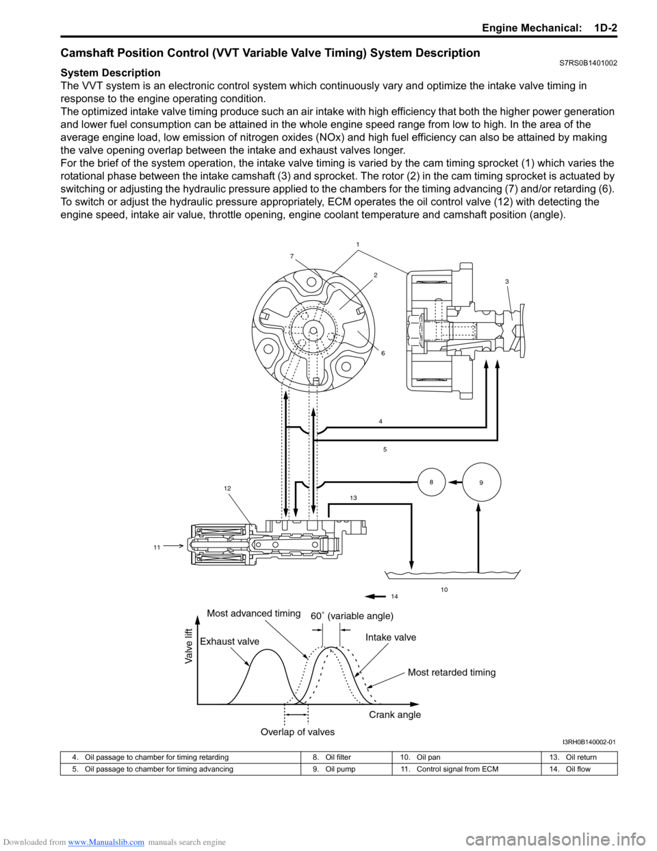
Camshaft Position Control (VVT Variable Valve Timing) System DescriptionS7RS0B1401002
System Description
The VVT system is an electronic control system which continuously vary and optimize the intake valve timing in
response to the engine operating condition.
The optimized intake valve timing produce such an air intake with high efficiency that both the higher power generation
and lower fuel consumption can be attained in the whole engine speed range from low to high. In the area of the
average engine load, low emission of nitrogen oxides (NOx) and high fuel efficiency can also be attained by making
the valve opening overlap between the intake and exhaust valves longer.
For the brief of the system operation, the intake valve timing is varied by the cam timing sprocket (1) which varies the
rotational phase between the intake camshaft (3) and sprocket . The rotor (2) in the cam timing sprocket is actuated by
switching or adjusting the hydraulic pressure applied to the chambers for the timing advancing (7) and/or retarding (6).
To switch or adjust the hydraulic pressure appropriately, ECM operates the oil control valve (12) with detecting the
engine speed, intake air value, throttle opening, engine coolant temperature and camshaft position (angle).
1
4
5
13
10
89
2
7
6
12
11
3
14
60� (variable angle)
Most retarded timing
Most advanced timing
Exhaust valve Intake valve
Crank angle
Overlap of valves
Valve lift
I3RH0B140002-01
4. Oil passage to chamber for timing retarding 8. Oil filter10. Oil pan 13. Oil return
5. Oil passage to chamber for timing advancing 9. Oil pump11. Control signal from ECM 14. Oil flow
Page 326 of 1496
Downloaded from www.Manualslib.com manuals search engine 1D-41 Engine Mechanical:
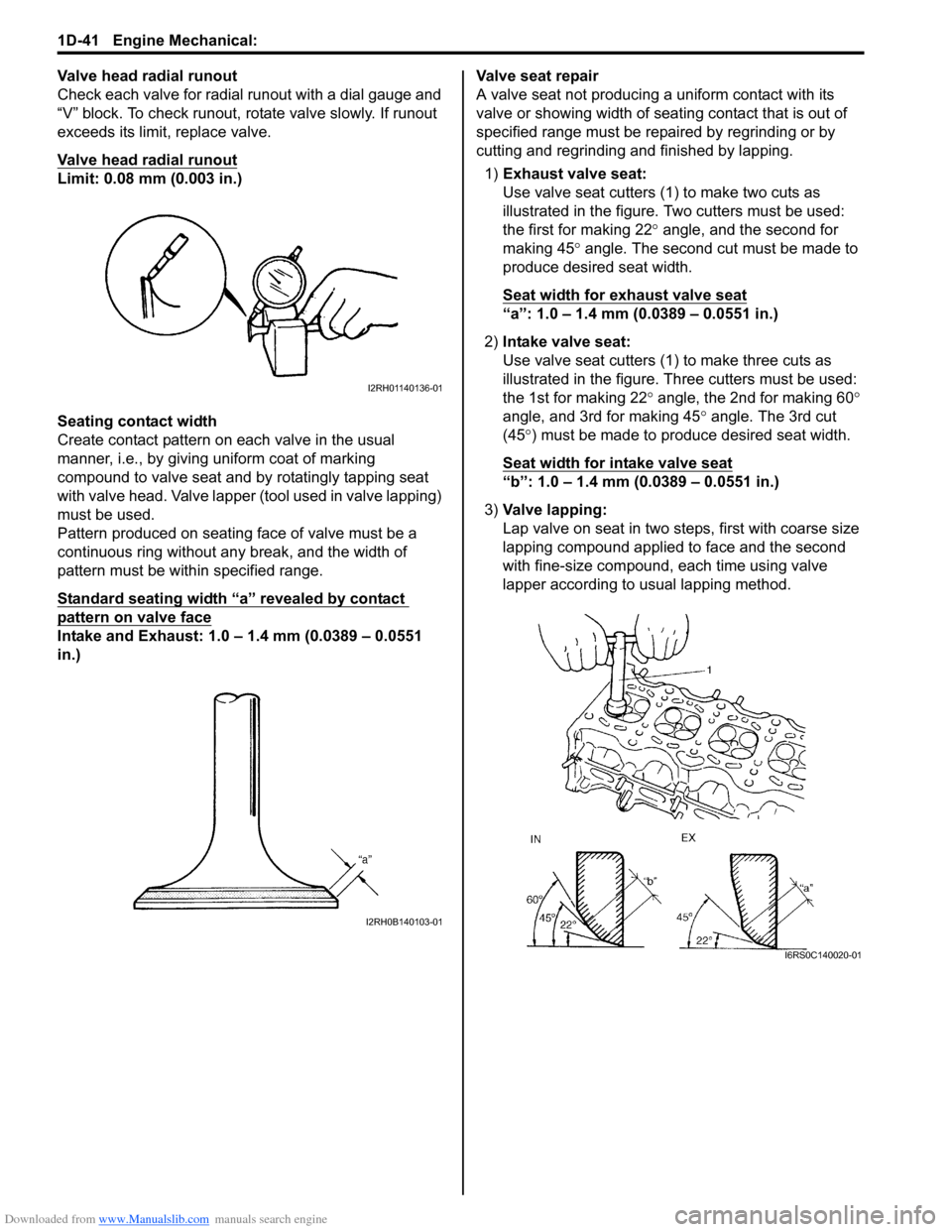
Valve head radial runout
Check each valve for radial runout with a dial gauge and
“V” block. To check runout, rotate valve slowly. If runout
exceeds its limit, replace valve.
Valve head radial runout
Limit: 0.08 mm (0.003 in.)
Seating contact width
Create contact pattern on each valve in the usual
manner, i.e., by giving uniform coat of marking
compound to valve seat and by rotatingly tapping seat
with valve head. Valve lapper (tool used in valve lapping)
must be used.
Pattern produced on seating face of valve must be a
continuous ring without any break, and the width of
pattern must be within specified range.
Standard seating width “a” revealed by contact
pattern on valve face
Intake and Exhaust: 1.0 – 1.4 mm (0.0389 – 0.0551
in.)Valve seat repair
A valve seat not producing
a uniform contact with its
valve or showing width of seating contact that is out of
specified range must be repaired by regrinding or by
cutting and regrinding and finished by lapping.
1) Exhaust valve seat:
Use valve seat cutters (1 ) to make two cuts as
illustrated in the figure. Two cutters must be used:
the first for making 22 ° angle, and the second for
making 45 ° angle. The second cut must be made to
produce desired seat width.
Seat width for exhaust valve seat
“a”: 1.0 – 1.4 mm (0.0389 – 0.0551 in.)
2) Intake valve seat:
Use valve seat cutters (1) to make three cuts as
illustrated in the figure. Th ree cutters must be used:
the 1st for making 22 ° angle, the 2nd for making 60 °
angle, and 3rd for making 45 ° angle. The 3rd cut
(45 °) must be made to produce desired seat width.
Seat width for intake valve seat
“b”: 1.0 – 1.4 mm (0.0389 – 0.0551 in.)
3) Valve lapping:
Lap valve on seat in two steps, first with coarse size
lapping compound applied to face and the second
with fine-size compound, each time using valve
lapper according to usual lapping method.
I2RH01140136-01
I2RH0B140103-01
I6RS0C140020-01
Page 334 of 1496
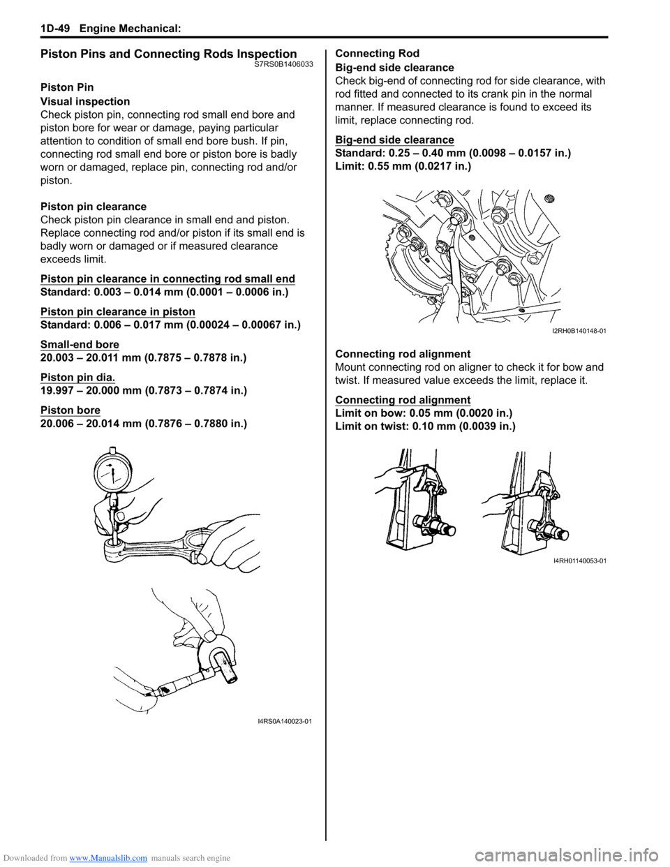
Downloaded from www.Manualslib.com manuals search engine 1D-49 Engine Mechanical:
Piston Pins and Connecting Rods InspectionS7RS0B1406033
Piston Pin
Visual inspection
Check piston pin, connecting rod small end bore and
piston bore for wear or damage, paying particular
attention to condition of small end bore bush. If pin,
connecting rod small end bore or piston bore is badly
worn or damaged, replace pin, connecting rod and/or
piston.
Piston pin clearance
Check piston pin clearance in small end and piston.
Replace connecting rod and/or piston if its small end is
badly worn or damaged or if measured clearance
exceeds limit.
Piston pin clearance in connecting rod small end
Standard: 0.003 – 0.014 mm (0.0001 – 0.0006 in.)
Piston pin clearance in piston
Standard: 0.006 – 0.017 mm (0.00024 – 0.00067 in.)
Small-end bore
20.003 – 20.011 mm (0.7875 – 0.7878 in.)
Piston pin dia.
19.997 – 20.000 mm (0.7873 – 0.7874 in.)
Piston bore
20.006 – 20.014 mm (0.7876 – 0.7880 in.)Connecting Rod
Big-end side clearance
Check big-end of connecting rod for side clearance, with
rod fitted and connected to its crank pin in the normal
manner. If measured clearance is found to exceed its
limit, replace connecting rod.
Big-end side clearance
Standard: 0.25 – 0.40 mm (0.0098 – 0.0157 in.)
Limit: 0.55 mm (0.0217 in.)
Connecting rod alignment
Mount connecting rod on aligner to check it for bow and
twist. If measured value exceeds the limit, replace it.
Connecting rod alignment
Limit on bow: 0.05 mm (0.0020 in.)
Limit on twist: 0.10 mm (0.0039 in.)
I4RS0A140023-01
I2RH0B140148-01
I4RH01140053-01