2008 SUZUKI SWIFT Cond rod
[x] Cancel search: Cond rodPage 484 of 1496
Downloaded from www.Manualslib.com manuals search engine 3A-6 Drive Shaft / Axle:
Front Drive Shaft Disassembly and ReassemblyS7RS0B3106004
Disassembly
Tripod joint
CAUTION!
• Disassembly of wheel side joint is not allowed. If any noise or damage exists in it,
replace it as assembly.
• Do not disassemble tripod joint spider. If any malcondition is found in it, replace it
as differential side joint assembly.
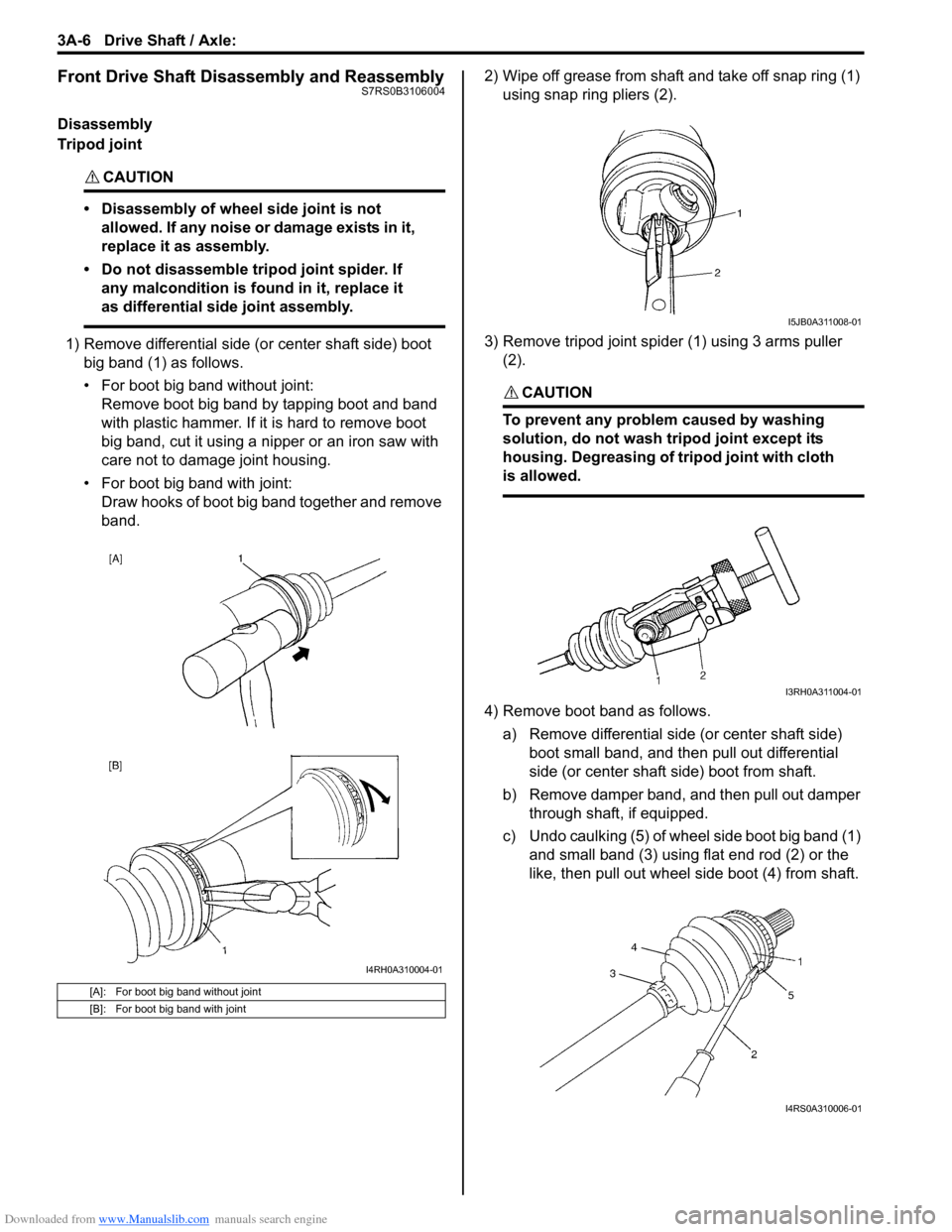
1) Remove differential side (or center shaft side) boot
big band (1) as follows.
• For boot big band without joint:Remove boot big band by tapping boot and band
with plastic hammer. If it is hard to remove boot
big band, cut it using a nipper or an iron saw with
care not to damage joint housing.
• For boot big band with joint: Draw hooks of boot big band together and remove
band. 2) Wipe off grease from shaft and take off snap ring (1)
using snap ring pliers (2).
3) Remove tripod joint spid er (1) using 3 arms puller
(2).
CAUTION!
To prevent any problem caused by washing
solution, do not wash tripod joint except its
housing. Degreasing of tr ipod joint with cloth
is allowed.
4) Remove boot band as follows.
a) Remove differential side (or center shaft side) boot small band, and then pull out differential
side (or center shaft side) boot from shaft.
b) Remove damper band, and then pull out damper through shaft, if equipped.
c) Undo caulking (5) of wheel side boot big band (1) and small band (3) using flat end rod (2) or the
like, then pull out wheel side boot (4) from shaft.
[A]: For boot big band without joint
[B]: For boot big band with joint
I4RH0A310004-01
I5JB0A311008-01
I3RH0A311004-01
I4RS0A310006-01
Page 500 of 1496
Downloaded from www.Manualslib.com manuals search engine 4A-2 Brake Control System and Diagnosis:
Brake Pedal Foot Protection System ConstructionS7RS0B4101004
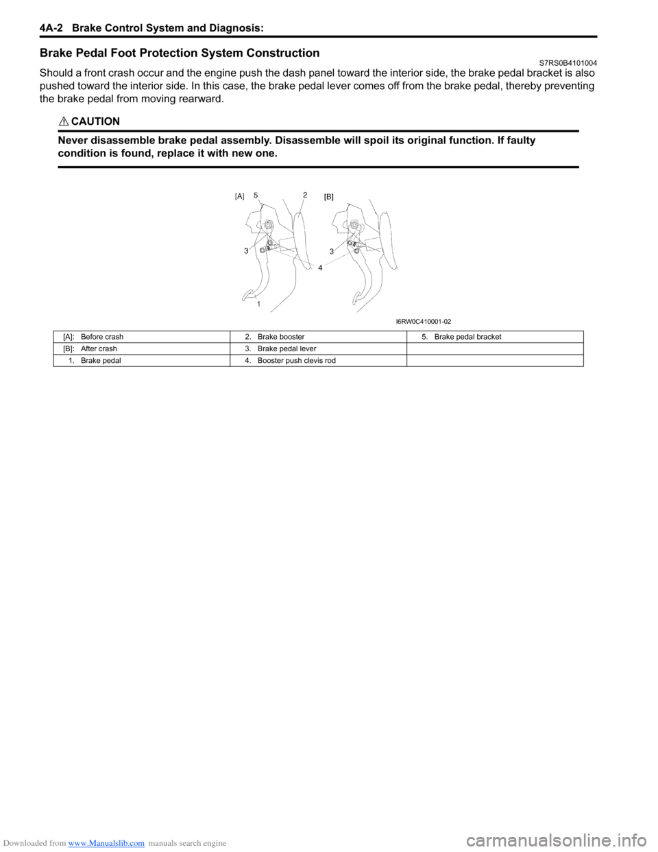
Should a front crash occur and the engine push the dash panel toward the interior side, the brake pedal bracket is also
pushed toward the interior side. In this case, the brake pedal lever comes off from the brake pedal, thereby preventing
the brake pedal from moving rearward.
CAUTION!
Never disassemble brake pedal assembly. Disassemble will spoil its original function. If faulty
condition is found, replace it with new one.
[A]: Before crash2. Brake booster5. Brake pedal bracket
[B]: After crash 3. Brake pedal lever
1. Brake pedal 4. Booster push clevis rod
I6RW0C410001-02
Page 505 of 1496
Downloaded from www.Manualslib.com manuals search engine Brake Control System and Diagnosis: 4A-7
Repair Instructions
Brake Pedal ComponentsS7RS0B4106019
CAUTION!
Never disassemble brake pedalassembly.
Disassemble will spoil its originalfunction. If
faulty condition is found, replaceit with new
one.
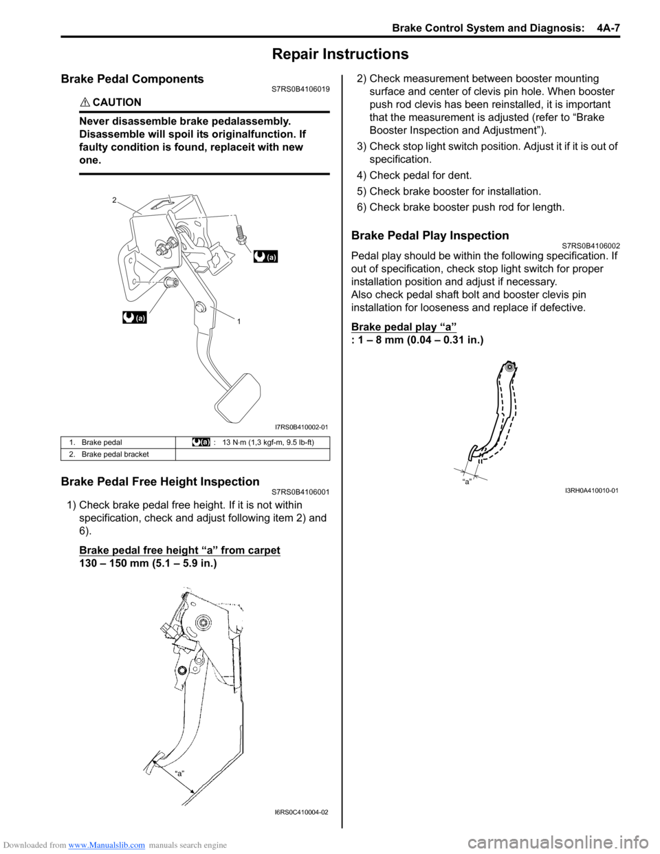
Brake Pedal Free Height InspectionS7RS0B4106001
1) Check brake pedal free height. If it is not within specification, check and ad just following item 2) and
6).
Brake pedal free height “a” from carpet
130 – 150 mm (5.1 – 5.9 in.) 2) Check measurement between booster mounting
surface and center of clevis pin hole. When booster
push rod clevis has been reinstalled, it is important
that the measurement is adj usted (refer to “Brake
Booster Inspection and Adjustment”).
3) Check stop light switch position . Adjust it if it is out of
specification.
4) Check pedal for dent.
5) Check brake booster for installation.
6) Check brake booster push rod for length.
Brake Pedal Play InspectionS7RS0B4106002
Pedal play should be within the following specification. If
out of specification, check stop light switch for proper
installation position and adjust if necessary.
Also check pedal shaft bolt and booster clevis pin
installation for looseness and replace if defective.
Brake pedal play
“a”
: 1 – 8 mm (0.04 – 0.31 in.)
1. Brake pedal : 13 N⋅m (1,3 kgf-m, 9.5 lb-ft)
2. Brake pedal bracket
(a) 1
2
(a)
I7RS0B410002-01
I6RS0C410004-02
“a”I3RH0A410010-01
Page 506 of 1496
Downloaded from www.Manualslib.com manuals search engine 4A-8 Brake Control System and Diagnosis:
Excessive Pedal Travel InspectionS7RS0B4106003
1) Start engine.
2) Depress brake pedal a few times.
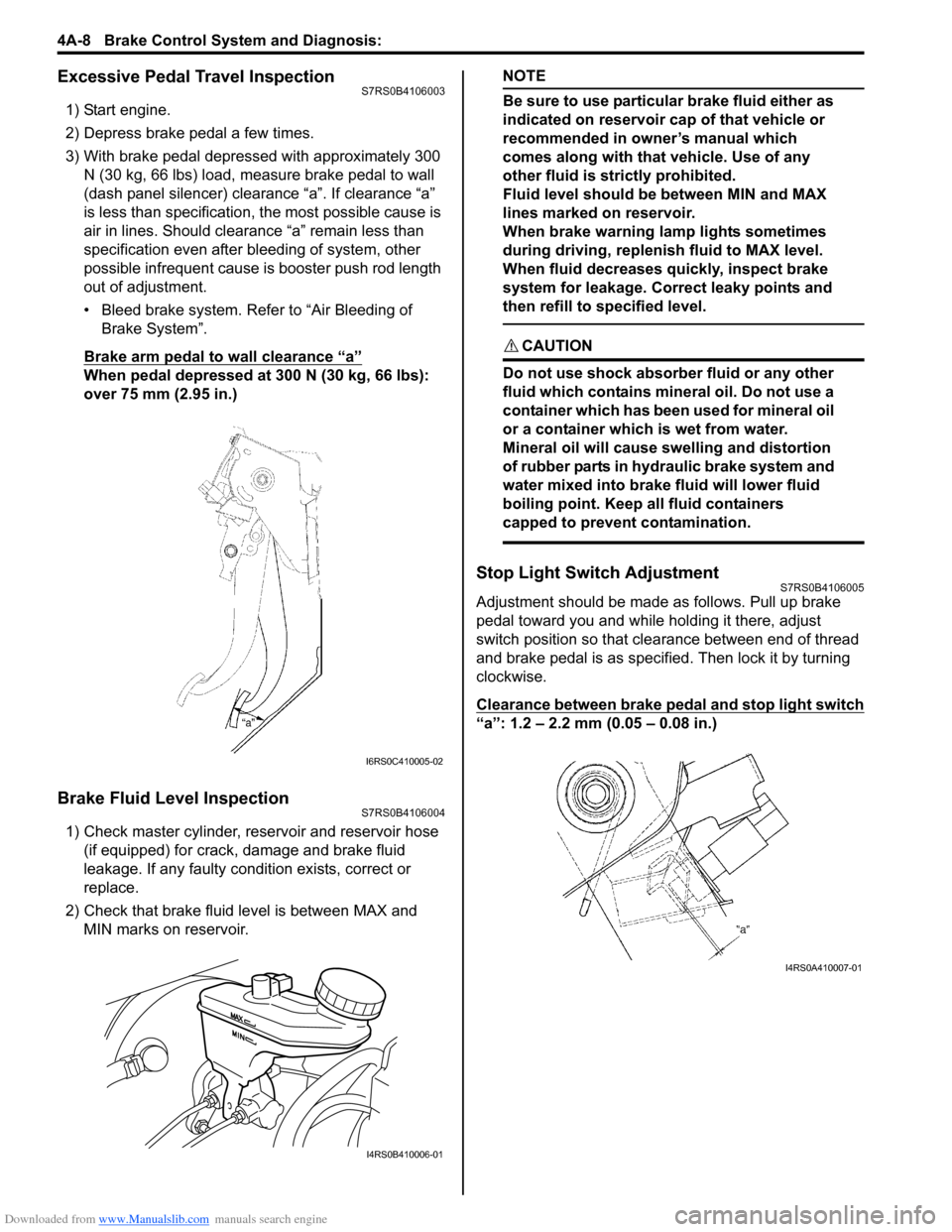
3) With brake pedal depressed with approximately 300 N (30 kg, 66 lbs) load, measure brake pedal to wall
(dash panel silencer) clearance “a”. If clearance “a”
is less than specification, the most possible cause is
air in lines. Should clearance “a” remain less than
specification even after bleeding of system, other
possible infrequent cause is booster push rod length
out of adjustment.
• Bleed brake system. Refer to “Air Bleeding of Brake System”.
Brake arm pedal to wall clearance “a”
When pedal depressed at 300 N (30 kg, 66 lbs):
over 75 mm (2.95 in.)
Brake Fluid Level InspectionS7RS0B4106004
1) Check master cylinder, reservoir and reservoir hose (if equipped) for crack, damage and brake fluid
leakage. If any faulty condition exists, correct or
replace.
2) Check that brake fluid level is between MAX and MIN marks on reservoir.
NOTE
Be sure to use particular brake fluid either as
indicated on reservoir cap of that vehicle or
recommended in owner’s manual which
comes along with that vehicle. Use of any
other fluid is strictly prohibited.
Fluid level should be between MIN and MAX
lines marked on reservoir.
When brake warning lamp lights sometimes
during driving, replenis h fluid to MAX level.
When fluid decreases quickly, inspect brake
system for leakage. Correct leaky points and
then refill to specified level.
CAUTION!
Do not use shock absorber fluid or any other
fluid which contains mineral oil. Do not use a
container which has been used for mineral oil
or a container which is wet from water.
Mineral oil will cause swelling and distortion
of rubber parts in hydraulic brake system and
water mixed into brake fluid will lower fluid
boiling point. Keep all fluid containers
capped to prevent contamination.
Stop Light Switch AdjustmentS7RS0B4106005
Adjustment should be made as follows. Pull up brake
pedal toward you and while holding it there, adjust
switch position so that clea rance between end of thread
and brake pedal is as specified. Then lock it by turning
clockwise.
Clearance between brake pedal and stop light switch
“a”: 1.2 – 2.2 mm (0.05 – 0.08 in.)
I6RS0C410005-02
I4RS0B410006-01
I4RS0A410007-01
Page 513 of 1496
Downloaded from www.Manualslib.com manuals search engine Brake Control System and Diagnosis: 4A-15
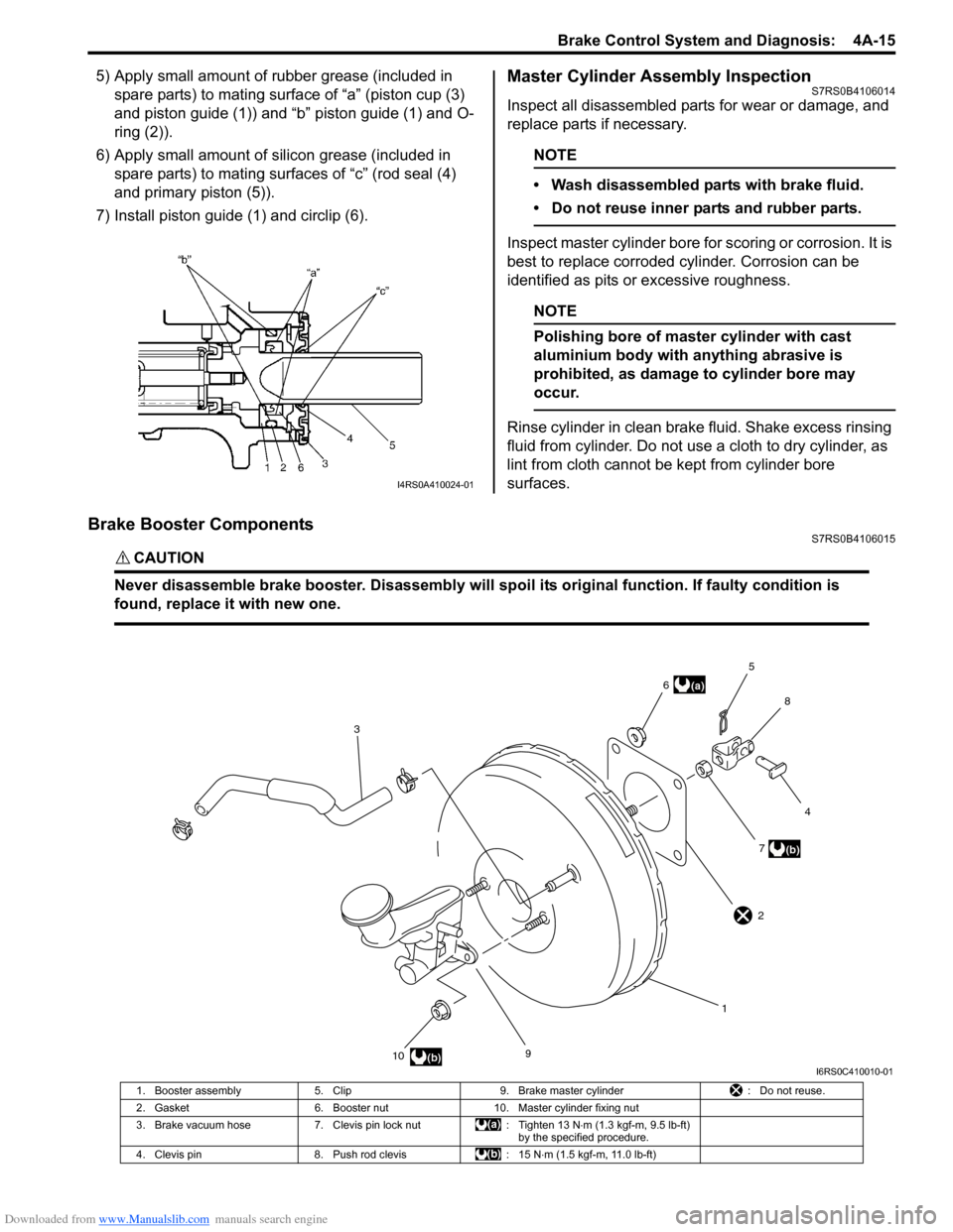
5) Apply small amount of rubber grease (included in spare parts) to mating surface of “a” (piston cup (3)
and piston guide (1)) and “b” piston guide (1) and O-
ring (2)).
6) Apply small amount of s ilicon grease (included in
spare parts) to mating surfaces of “c” (rod seal (4)
and primary piston (5)).
7) Install piston guide (1) and circlip (6).Master Cylinder Assembly InspectionS7RS0B4106014
Inspect all disassembled parts for wear or damage, and
replace parts if necessary.
NOTE
• Wash disassembled parts with brake fluid.
• Do not reuse inner parts and rubber parts.
Inspect master cylinder bore for scoring or corrosion. It is
best to replace corroded cylinder. Corrosion can be
identified as pits or excessive roughness.
NOTE
Polishing bore of master cylinder with cast
aluminium body with anything abrasive is
prohibited, as damage to cylinder bore may
occur.
Rinse cylinder in clean brake fluid. Shake excess rinsing
fluid from cylinder. Do not use a cloth to dry cylinder, as
lint from cloth cannot be kept from cylinder bore
surfaces.
Brake Booster ComponentsS7RS0B4106015
CAUTION!
Never disassemble brake booster. Disassembly will spoi l its original function. If faulty condition is
found, replace it with new one.
I4RS0A410024-01
9
10 17
4
8
5
6
3
(b)
(a)
(b)
2
I6RS0C410010-01
1. Booster assembly 5. Clip 9. Brake master cylinder : Do not reuse.
2. Gasket 6. Booster nut 10. Master cylinder fixing nut
3. Brake vacuum hose 7. Clevis pin lock nut : Tighten 13 N⋅m (1.3 kgf-m, 9.5 lb-ft)
by the specified procedure.
4. Clevis pin 8. Push rod clevis : 15 N⋅m (1.5 kgf-m, 11.0 lb-ft)
Page 515 of 1496
Downloaded from www.Manualslib.com manuals search engine Brake Control System and Diagnosis: 4A-17
2) Hold brake pedal depressed for 30 seconds. If pedal height does not change, condition is good. But it isn’t
if pedal rises.
Brake Booster Removal and InstallationS7RS0B4106017
Removal
1) Recover refrigerant from A/C system by using recovery and recycling equipment referring to
“Operation Procedure for Refrigerant Charge in
Section 7B” or “Operation Procedure for Refrigerant
Charge in Section 7B”.
2) Remove master cylinder assembly from booster referring to “Master Cylin der Assembly Removal and
Installation”.
3) Remove cowl top cover and cowl top panel referring to “Cowl Top Components in Section 9K”.
4) Remove suction hose referring to “Major Components of A/C System in Section 7B” or “Major
Components of A/C System in Section 7B”.
5) Disconnect vacuum hose from booster referring to “Brake Booster Components”.
6) Remove push rod clevis pin and booster mounting nuts and then remove booster. Installation
1) Loosen brake pedal bracket mounting bolt.
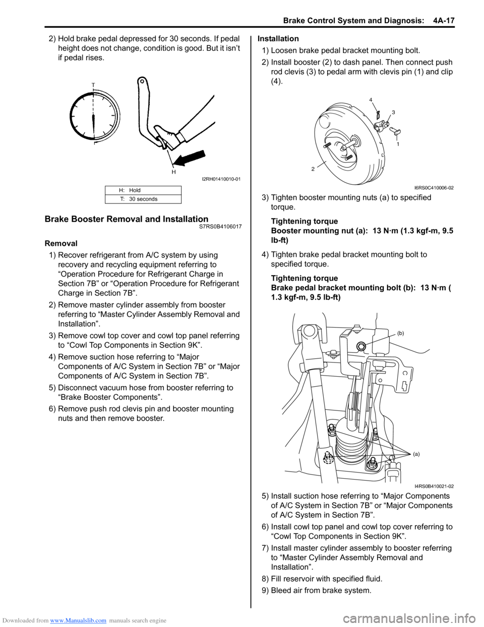
2) Install booster (2) to dash panel. Then connect push rod clevis (3) to pedal arm with clevis pin (1) and clip
(4).
3) Tighten booster mounting nuts (a) to specified torque.
Tightening torque
Booster mounting nut (a): 13 N·m (1.3 kgf-m, 9.5
lb-ft)
4) Tighten brake pedal bracket mounting bolt to specified torque.
Tightening torque
Brake pedal bracket mounting bolt (b): 13 N·m (
1.3 kgf-m, 9.5 lb-ft)
5) Install suction hose referring to “Major Components of A/C System in Section 7B” or “Major Components
of A/C System in Section 7B”.
6) Install cowl top panel and cowl top cover referring to
“Cowl Top Components in Section 9K”.
7) Install master cylinder assembly to booster referring to “Master Cylinder Assembly Removal and
Installation”.
8) Fill reservoir with specified fluid.
9) Bleed air from brake system.
H: Hold
T: 30 seconds
I2RH01410010-01
1
2 4
3
I6RS0C410006-02
(b)
(a)
I4RS0B410021-02
Page 579 of 1496
Downloaded from www.Manualslib.com manuals search engine Electronic Stability Program: 4F-5
Yaw rate / G sensor
The yaw rate / G sensor consists of the yaw rate (angular velocity in the vehicle turning direction) sensor and right-left
G (acceleration in right-left direction) sensor and is mounted to the P/S controller B/K at the lower part of the center
console. It detects the angular velocity in the vehicle turn ing direction and movement in the right-left direction, and
then it sends that information to ESP ® control module.
Wheel speed sensor
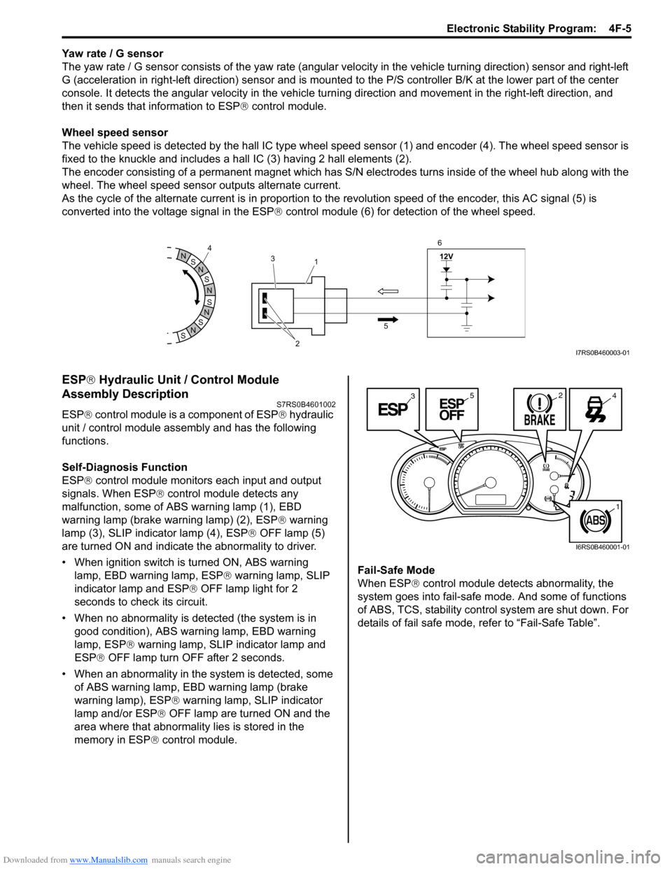
The vehicle speed is detected by the hall IC type wheel speed sensor (1) and encoder (4). The wheel speed sensor is
fixed to the knuckle and includes a hall IC (3) having 2 hall elements (2).
The encoder consisting of a permanent ma gnet which has S/N electrodes turns inside of the wheel hub along with the
wheel. The wheel speed sensor outputs alternate current.
As the cycle of the alternate current is in proportion to the revolution speed of the encoder, this AC signal (5) is
converted into the voltage signal in the ESP ® control module (6) for detection of the wheel speed.
ESP ® Hydraulic Unit / Control Module
Assembly Description
S7RS0B4601002
ESP ® control module is a component of ESP ® hydraulic
unit / control module assembly and has the following
functions.
Self-Diagnosis Function
ESP ® control module monitors each input and output
signals. When ESP ® control module detects any
malfunction, some of ABS warning lamp (1), EBD
warning lamp (brake warning lamp) (2), ESP ® warning
lamp (3), SLIP indicator lamp (4), ESP ® OFF lamp (5)
are turned ON and indicate the abnormality to driver.
• When ignition switch is turned ON, ABS warning lamp, EBD warning lamp, ESP ® warning lamp, SLIP
indicator lamp and ESP ® OFF lamp light for 2
seconds to check its circuit.
• When no abnormality is detected (the system is in good condition), ABS warning lamp, EBD warning
lamp, ESP ® warning lamp, SLIP indicator lamp and
ESP ® OFF lamp turn OFF after 2 seconds.
• When an abnormality in the system is detected, some of ABS warning lamp, EBD warning lamp (brake
warning lamp), ESP ® warning lamp, SLIP indicator
lamp and/or ESP ® OFF lamp are turned ON and the
area where that abnormality lies is stored in the
memory in ESP ® control module. Fail-Safe Mode
When ESP
® control module detects abnormality, the
system goes into fail-safe mode. And some of functions
of ABS, TCS, stability control system are shut down. For
details of fail safe mode, re fer to “Fail-Safe Table”.
S
N
S
N
S
N
N
S
N
S
12V
2
3
1
5
4
6I7RS0B460003-01
3245
1
I6RS0B460001-01
Page 647 of 1496
Downloaded from www.Manualslib.com manuals search engine Automatic Transmission/Transaxle: 5A-3
General Description
A/T DescriptionS7RS0B5101001
This automatic transaxle is electronic control full automatic transaxle with forward 4-speed and reverse 1-speed.
The torque converter is a 3-element, 1-step and 2-phase type and is equipped with an automatically controlled lock-up
mechanism.
The gear change device consists of a ravigneau type planet ary gear unit, 3 multiple disc type clutches, 3 multiple disc
type brakes and 2 one-way clutches.
The hydraulic pressure control device consists of a valve body assembly, pressure control solenoid valve (linear
solenoid), 2 shift solenoid va lves, TCC pressure control solenoid valve (lin ear solenoid) and a timing solenoid valve.
Optimum line pressure complying with engine torque is produced by the pressure control solenoid valve in
dependence upon control signal from transmission control module (TCM). This makes it possible to control the line
pressure with high accuracy in accordance with the engine power and running conditions to achieve smooth shifting
characteristics and high efficiency.
A clutch-to-clutch control system is prov ided for shifting between 3rd gear and 4th gear. This clutch-to-clutch control
system is made to function optimally , so that hydraulic pressure controls such as shown below are conducted.
• When upshifting from 3rd gear to 4th gear, to adjust the drain hydraulic pressure at releasing the forward clutch, a
timing solenoid valve is used to switch a hydraulic passage with an orifice to another during shifting.
• When downshifting from 4th gear to 3rd gear, to adjust the line pressure applied to the forward clutch at engaging the forward clutch, a timing solenoid valve is used to s witch a hydraulic passage with an orifice to another during
shifting.
• When upshifting from 3rd gear to 4th gear with engine throttle opened, to optimize the line pressure applied to the forward clutch at releasing the forward clutch, the learning control is processed to compensate the switching timing
of the timing solenoid at every shifting.
• When downshifting from 4th gear to 3rd gear with engine throttle opened, to optimize the line pressure applied to
the forward clutch at engaging the forw ard clutch, the learning control is processed to compensate the line pressure
at every shifting.
Employing the ravigneau type planetary gear unit and this clutch-to-clutch control system greatly simplifies the
construction to make possible a lightweight and compact transaxle.
A line pressure learning control is conducted to provide opti mum shifting time at every upshifting with engine throttle
opened. If long upshifting time is detected, the subsequent line pressure applied during upshifting is intensified. On the
contrary, if short upshifting time is detected, the subs equent line pressure applied during upshifting is weakened.
Slip controlled lock-up function
Even at a lower speed than when the TCC gets engaged completely, control over the TCC pressure control solenoid
works to cause the TCC to slip (be engaged slightly), ther eby improving the transmission efficiency. While such slip
control is being executed, the oil pressure applied to the TCC is controlled by the TCC pressure control solenoid so
that the difference between the engine speed and the input shaft speed becomes close to the specified value.
Also, during deceleration, the TCC is made to slip (be enga ged slightly) to raise the engine speed and enlarge the fuel
cut operation range so that better fuel consumption is achieved.
Due to this reason, it is absolutely necessary for the automati c transmission to use ATF suitable for slip control. Use of
any fluid other than the specified ATF may cause j uddering or some other faulty condition to occur.