2008 SUZUKI SWIFT steering lock
[x] Cancel search: steering lockPage 931 of 1496
Downloaded from www.Manualslib.com manuals search engine Power Assisted Steering System: 6C-49
Special Tools and Equipment
Recommended Service MaterialS7RS0B6308001
NOTE
Required service material is also described in the following.
“Steering Gear Case Assembly Components”
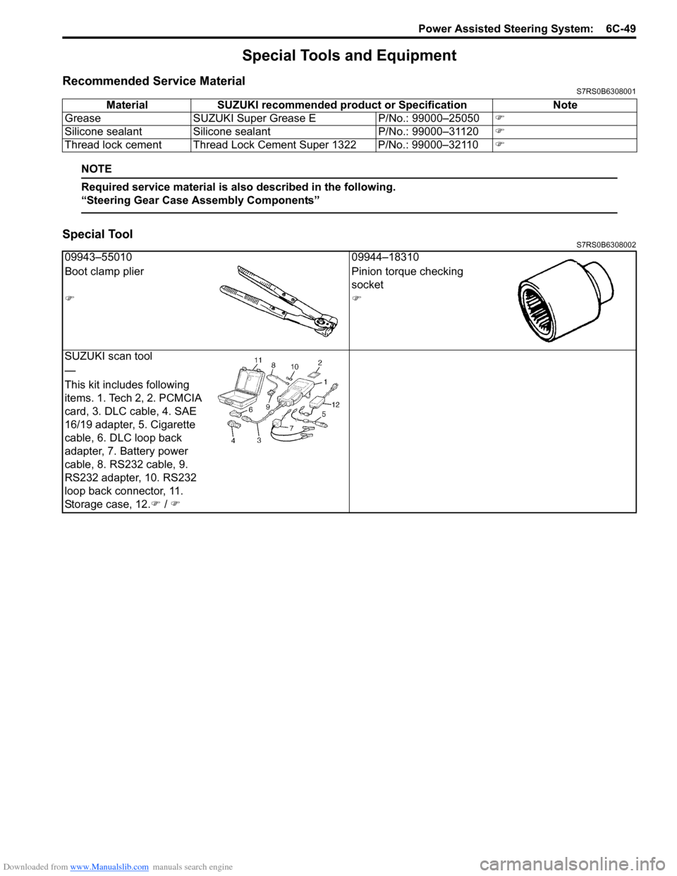
Special ToolS7RS0B6308002
Material SUZUKI recommended product or Specification Note
Grease SUZUKI Super Grease E P/No.: 99000–25050�)
Silicone sealant Silicone sealant P/No.: 99000–31120�)
Thread lock cement Thread Lock Cement Super 1322 P/No.: 99000–32110 �)
09943–5501009944–18310
Boot clamp plier Pinion torque checking
socket
�)�)
SUZUKI scan tool
—
This kit includes following
items. 1. Tech 2, 2. PCMCIA
card, 3. DLC cable, 4. SAE
16/19 adapter, 5. Cigarette
cable, 6. DLC loop back
adapter, 7. Battery power
cable, 8. RS232 cable, 9.
RS232 adapter, 10. RS232
loop back connector, 11.
Storage case, 12. �) / �)
Page 944 of 1496

Downloaded from www.Manualslib.com manuals search engine 7A-8 Heater and Ventilation:
b. Move temperature control lever (1) and air flow control plate (2) fully to the arrow direction. c. Fix temperature control inner cable (1) to pin of
temperature control lever and air flow control inner
cable (2) to pin of air fl ow control plate, and then
fix each outer cable (3) to each cable lock clamp.
NOTE
After installing control cables, make sure that
control lever and plate move smoothly and
stop at proper position.
• Enable air bag system referring to “Enabling Air Bag System in Section 8B”.
• Make sure that air flow outlet changes correctly as air flow selector is changed.
[A]: LH steering vehicle [B]: RH steering vehicle
1
2
[A]
[B]
1
2
I4RS0B710014-01
[A]: LH steering vehicle [B]: RH steering vehicle
1
2
[B] [A] 3
3
1
3
23
I4RS0B710015-01
Page 1026 of 1496
Downloaded from www.Manualslib.com manuals search engine 7B-78 Air Conditioning System: Automatic Type
Inside Air Temperature Sensor Removal and
Installation
S7RS0B7226018
Removal1) Disconnect negative (–) cable at battery.
2) Remove steering column hole cover.
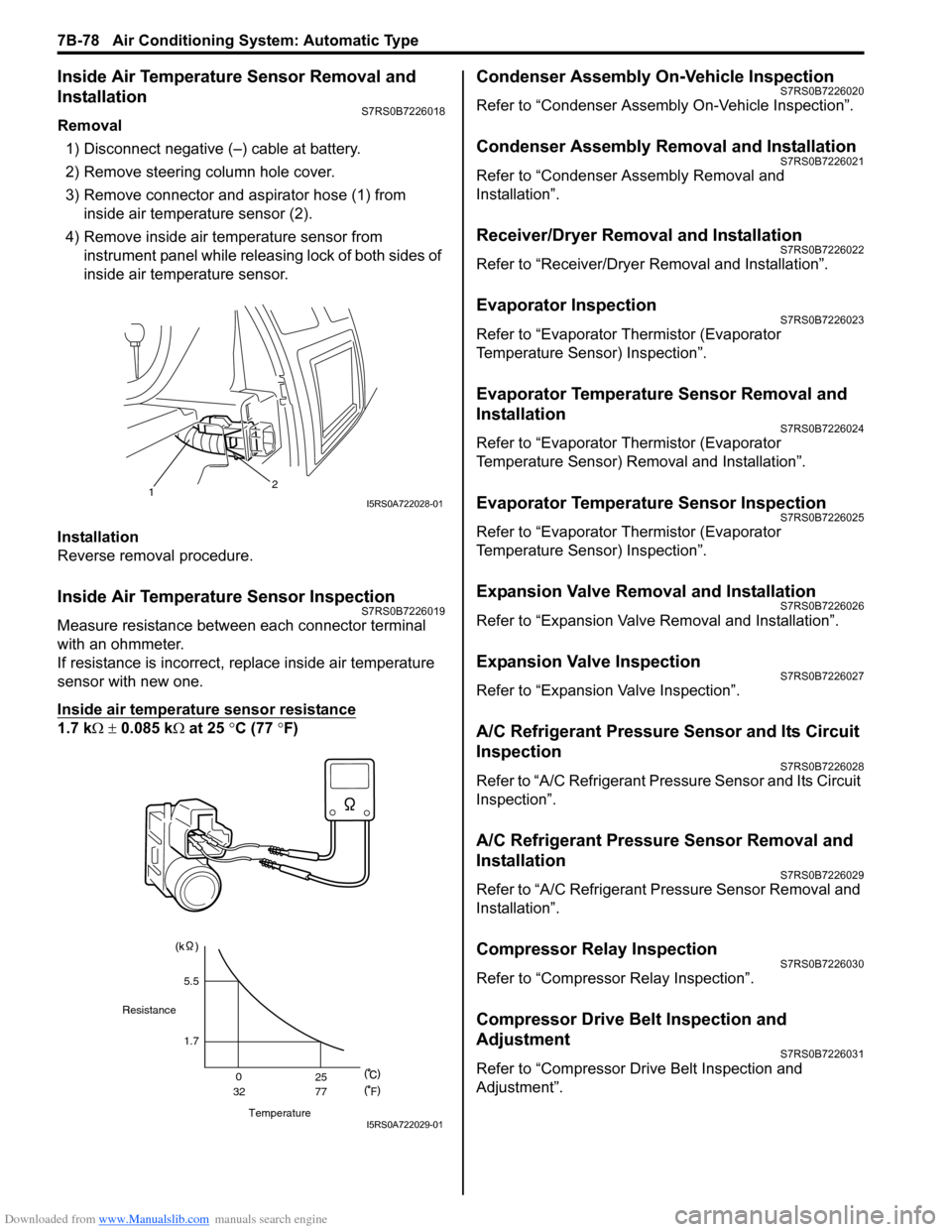
3) Remove connector and aspirator hose (1) from inside air temperature sensor (2).
4) Remove inside air temperature sensor from instrument panel while releas ing lock of both sides of
inside air temperature sensor.
Installation
Reverse removal procedure.
Inside Air Temperature Sensor InspectionS7RS0B7226019
Measure resistance between each connector terminal
with an ohmmeter.
If resistance is incorrect, replace inside air temperature
sensor with new one.
Inside air temperature sensor resistance
1.7 k Ω ± 0.085 k Ω at 25 °C (77 ° F)
Condenser Assembly On-Vehicle InspectionS7RS0B7226020
Refer to “Condenser Assembly On-Vehicle Inspection”.
Condenser Assembly Removal and InstallationS7RS0B7226021
Refer to “Condenser Assembly Removal and
Installation”.
Receiver/Dryer Removal and InstallationS7RS0B7226022
Refer to “Receiver/Dryer Removal and Installation”.
Evaporator InspectionS7RS0B7226023
Refer to “Evaporator Thermistor (Evaporator
Temperature Sensor) Inspection”.
Evaporator Temperature Sensor Removal and
Installation
S7RS0B7226024
Refer to “Evaporator Thermistor (Evaporator
Temperature Sensor) Removal and Installation”.
Evaporator Temperature Sensor InspectionS7RS0B7226025
Refer to “Evaporator Thermistor (Evaporator
Temperature Sensor) Inspection”.
Expansion Valve Removal and InstallationS7RS0B7226026
Refer to “Expansion Valve Removal and Installation”.
Expansion Valve InspectionS7RS0B7226027
Refer to “Expansion Valve Inspection”.
A/C Refrigerant Pressure Sensor and Its Circuit
Inspection
S7RS0B7226028
Refer to “A/C Refrigerant Pressure Sensor and Its Circuit
Inspection”.
A/C Refrigerant Pressure Sensor Removal and
Installation
S7RS0B7226029
Refer to “A/C Refrigerant Pressure Sensor Removal and
Installation”.
Compressor Relay InspectionS7RS0B7226030
Refer to “Compressor Relay Inspection”.
Compressor Drive Belt Inspection and
Adjustment
S7RS0B7226031
Refer to “Compressor Drive Belt Inspection and
Adjustment”.
12I5RS0A722028-01
Temperature
Resistance
1.7
0
32 25
77
F
5.5
I5RS0A722029-01
Page 1085 of 1496
Downloaded from www.Manualslib.com manuals search engine Air Bag System: 8B-47
NOTE
Upon completion of inspection and repair work, perform the following items.
• Reconnect all air bag system components and ensure all components are properly mounted.
• Clear DTCs referring to “DTC Clearance”, if any.
• Repeat “Air Bag Diagnostic System Check” to confirm that the trouble has been corrected.
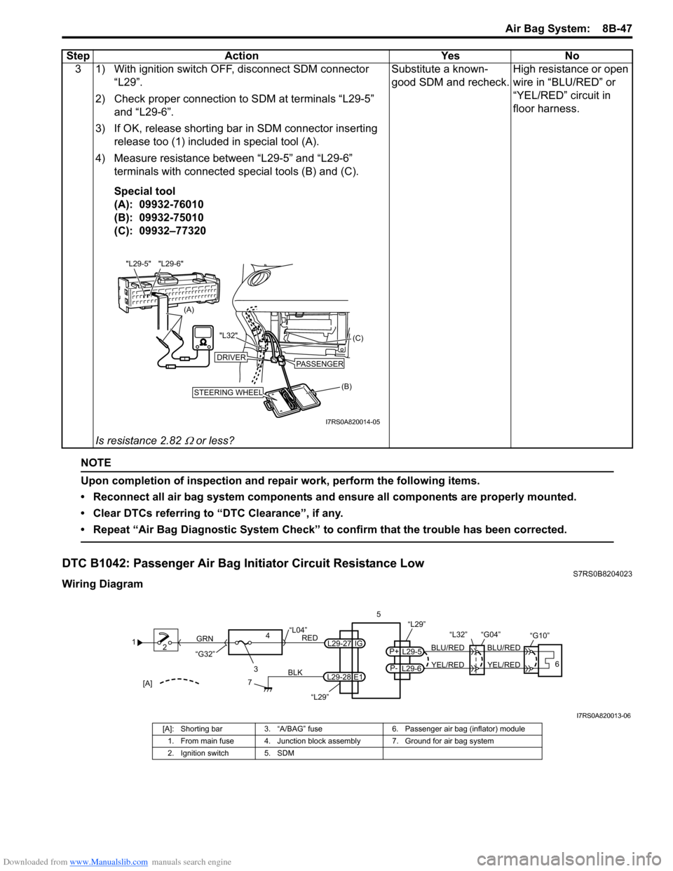
DTC B1042: Passenger Air Bag Initiator Circuit Resistance LowS7RS0B8204023
Wiring Diagram3 1) With ignition switch OFF, disconnect SDM connector
“L29”.
2) Check proper connection to SDM at terminals “L29-5” and “L29-6”.
3) If OK, release shorting bar in SDM connector inserting
release too (1) included in special tool (A).
4) Measure resistance between “L29-5” and “L29-6” terminals with connected special tools (B) and (C).
Special tool
(A): 09932-76010
(B): 09932-75010
(C): 09932–77320
Is resistance 2.82
Ω or less? Substitute a known-
good SDM and recheck.
High resistance or open
wire in “BLU/RED” or
“YEL/RED” circuit in
floor harness.
Step Action Yes No
(A)
"L29-6"
"L29-5"
(B) (C)
"L32"STEERING WHEEL
DRIVERPASSENGER
I7RS0A820014-05
1
2
3
GRN
RED
7
BLK
L29-27
L29-28 IG
E1
4
“L29”
“L04”
“G32”
“L29”
L29-5
P+
L29-6
P-YEL/RED
BLU/RED
YEL/RED
BLU/RED
56
“L32” “G04”
“G10”
[A]
I7RS0A820013-06
[A]: Shorting bar
3. “A/BAG” fuse 6. Passenger air bag (inflator) module
1. From main fuse 4. Junction block assembly 7. Ground for air bag system
2. Ignition switch 5. SDM
Page 1088 of 1496
Downloaded from www.Manualslib.com manuals search engine 8B-50 Air Bag System:
NOTE
Upon completion of inspection and repair work, perform the following items.
• Reconnect all air bag system components and ensure all components are properly mounted.
• Clear DTCs referring to “DTC Clearance”, if any.
• Repeat “Air Bag Diagnostic System Check” to confirm that the trouble has been corrected.
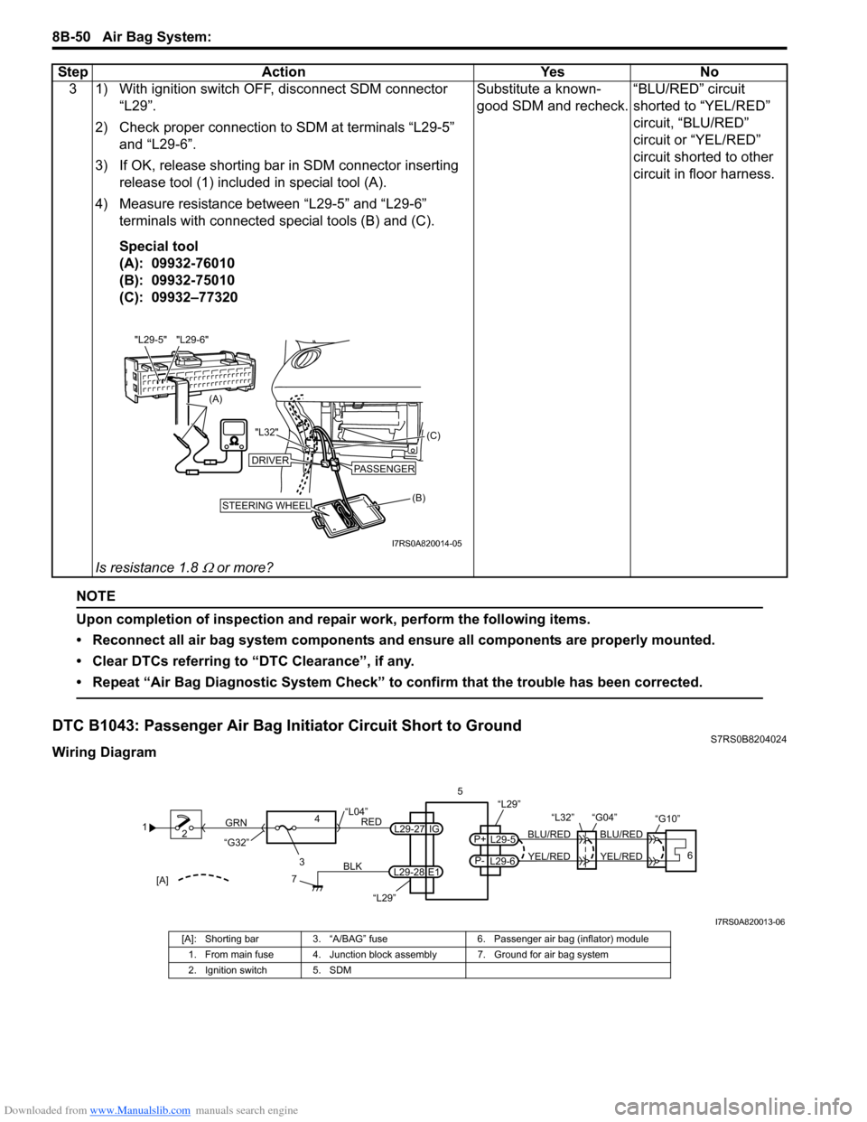
DTC B1043: Passenger Air Bag Initiator Circuit Short to GroundS7RS0B8204024
Wiring Diagram3 1) With ignition switch OFF, disconnect SDM connector
“L29”.
2) Check proper connection to SDM at terminals “L29-5” and “L29-6”.
3) If OK, release shorting bar in SDM connector inserting
release tool (1) included in special tool (A).
4) Measure resistance between “L29-5” and “L29-6” terminals with connected special tools (B) and (C).
Special tool
(A): 09932-76010
(B): 09932-75010
(C): 09932–77320
Is resistance 1.8
Ω or more? Substitute a known-
good SDM and recheck.
“BLU/RED” circuit
shorted to “YEL/RED”
circuit, “BLU/RED”
circuit or “YEL/RED”
circuit shorted to other
circuit in floor harness.
Step Action Yes No
(A)
"L29-6"
"L29-5"
(B) (C)
"L32"STEERING WHEEL
DRIVERPASSENGER
I7RS0A820014-05
1
2
3
GRN
RED
7
BLK
L29-27
L29-28 IG
E1
4
“L29”
“L04”
“G32”
“L29”
L29-5
P+
L29-6
P-YEL/RED
BLU/RED
YEL/RED
BLU/RED
56
“L32” “G04”
“G10”
[A]
I7RS0A820013-06
[A]: Shorting bar
3. “A/BAG” fuse 6. Passenger air bag (inflator) module
1. From main fuse 4. Junction block assembly 7. Ground for air bag system
2. Ignition switch 5. SDM
Page 1091 of 1496
Downloaded from www.Manualslib.com manuals search engine Air Bag System: 8B-53
NOTE
Upon completion of inspection and repair work, perform the following items.
• Reconnect all air bag system components and ensure all components are properly mounted.
• Clear DTCs referring to “DTC Clearance”, if any.
• Repeat “Air Bag Diagnostic System Check” to confirm that the trouble has been corrected.
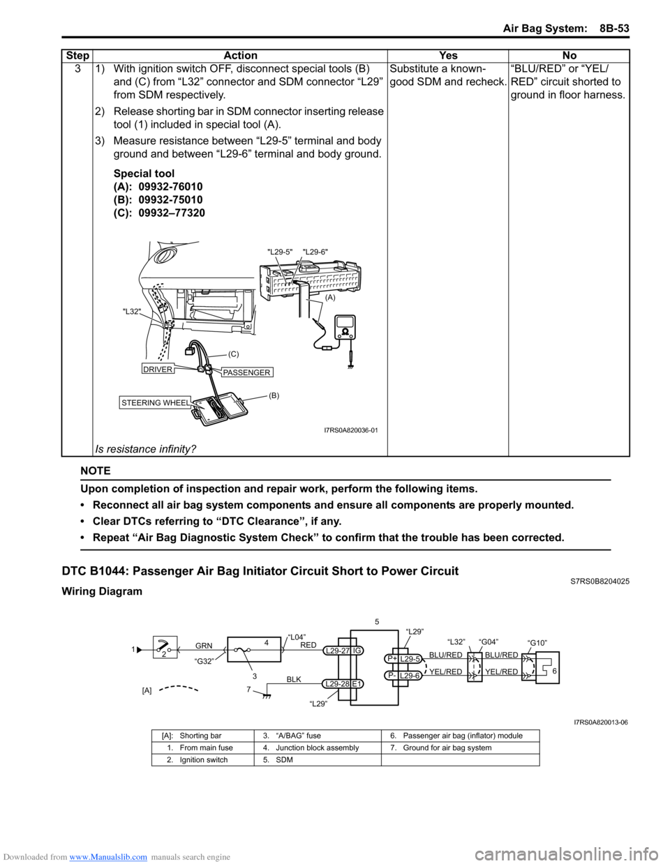
DTC B1044: Passenger Air Bag Initiator Circuit Short to Power CircuitS7RS0B8204025
Wiring Diagram3 1) With ignition switch OFF, disconnect special tools (B)
and (C) from “L32” connector and SDM connector “L29”
from SDM respectively.
2) Release shorting bar in SDM connector inserting release tool (1) included in special tool (A).
3) Measure resistance between “L29-5” terminal and body ground and between “L29-6” terminal and body ground.
Special tool
(A): 09932-76010
(B): 09932-75010
(C): 09932–77320
Is resistance infinity? Substitute a known-
good SDM and recheck.
“BLU/RED” or “YEL/
RED” circuit shorted to
ground in floor harness.
Step Action Yes No
(B)
(C)
"L32"
STEERING WHEEL
DRIVERPASSENGER
(A)
"L29-6"
"L29-5"
I7RS0A820036-01
1
2
3
GRN
RED
7
BLK
L29-27
L29-28 IG
E1
4
“L29”
“L04”
“G32”
“L29”
L29-5
P+
L29-6
P-YEL/RED
BLU/RED
YEL/RED
BLU/RED
56
“L32” “G04”
“G10”
[A]
I7RS0A820013-06
[A]: Shorting bar
3. “A/BAG” fuse 6. Passenger air bag (inflator) module
1. From main fuse 4. Junction block assembly 7. Ground for air bag system
2. Ignition switch 5. SDM
Page 1096 of 1496
Downloaded from www.Manualslib.com manuals search engine 8B-58 Air Bag System:
NOTE
Upon completion of inspection and repair work, perform the following items.
• Reconnect all air bag system components and ensure all components are properly mounted.
• Clear DTCs referring to “DTC Clearance”, if any.
• Repeat “Air Bag Diagnostic System Check” to confirm that the trouble has been corrected.
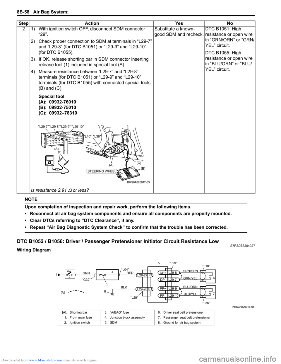
DTC B1052 / B1056: Driver / Passenger Pretensioner Initiator Circuit Resistance LowS7RS0B8204027
Wiring Diagram2 1) With ignition switch OFF, disconnect SDM connector
“29”.
2) Check proper connection to SDM at terminals in “L29-7” and “L29-8” (for DTC B1051) or “L29-9” and “L29-10”
(for DTC B1055).
3) If OK, release shorting bar in SDM connector inserting
release tool (1) included in special tool (A).
4) Measure resistance between “L29-7” and “L29-8” terminals (for DTC B1051) or “L29-9” and “L29-10”
terminals (for DTC B1055) with connected special tools
(B) and (C).
Special tool
(A): 09932-76010
(B): 09932-75010
(C): 09932–78310
Is resistance 2.91
Ω or less? Substitute a known-
good SDM and recheck.
DTC B1051: High
resistance or open wire
in “GRN/ORN” or “GRN/
YEL” circuit.
DTC B1055: High
resistance or open wire
in “BLU/ORN” or “BLU/
YEL” circuit.
Step Action Yes No
(A)
"L29-8" "L29-9" "L29-10"
"L29-7"
STEERING WHEEL(B)
(C)
(A)
"L10", "L36"
I7RS0A820017-03
1
2
3
GRN
RED
8
BLK
L29-27
L29-28 IG
E1
4
“L29”
“L04”
“G32”
“L29”
L29-8
DP+
L29-7
DP-GRN/YEL
GRN/ORN
56
“L10”
L29-9
PP+
L29-10
PP-BLU/YEL
BLU/ORN7
“L36”[A]
I7RS0A820016-05
[A]: Shorting bar 3. “A/BAG” fuse 6. Driver seat belt pretensioner
1. From main fuse 4. Junction block assembly 7. Passenger seat belt pretensioner
2. Ignition switch 5. SDM 8. Ground for air bag system
Page 1098 of 1496
Downloaded from www.Manualslib.com manuals search engine 8B-60 Air Bag System:
NOTE
Upon completion of inspection and repair work, perform the following items.
• Reconnect all air bag system components and ensure all components are properly mounted.
• Clear DTCs referring to “DTC Clearance”, if any.
• Repeat “Air Bag Diagnostic System Check” to confirm that the trouble has been corrected.
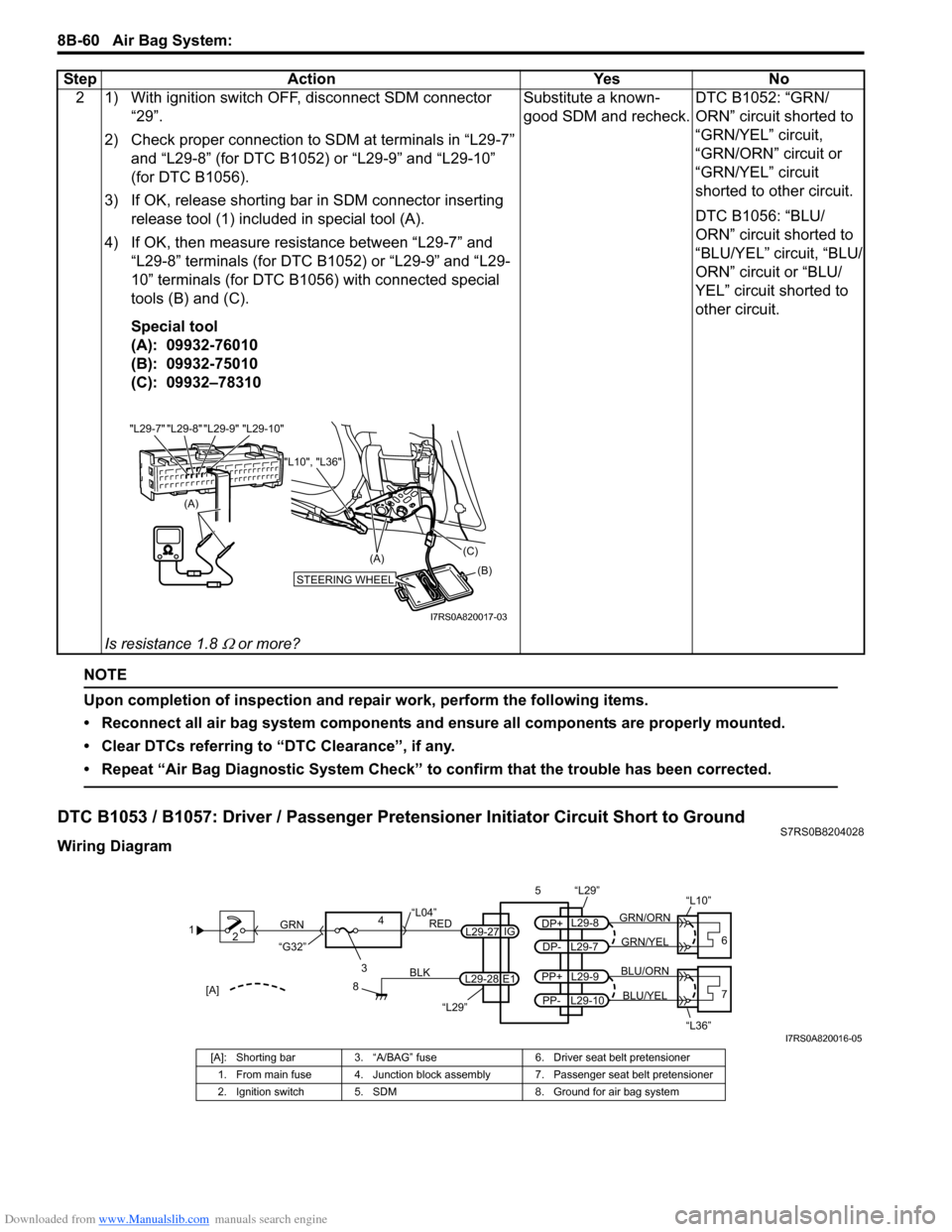
DTC B1053 / B1057: Driver / Passenger Pretensioner Initiator Circuit Short to GroundS7RS0B8204028
Wiring Diagram2 1) With ignition switch OFF, disconnect SDM connector
“29”.
2) Check proper connection to SDM at terminals in “L29-7” and “L29-8” (for DTC B1052) or “L29-9” and “L29-10”
(for DTC B1056).
3) If OK, release shorting bar in SDM connector inserting
release tool (1) included in special tool (A).
4) If OK, then measure resistance between “L29-7” and “L29-8” terminals (for DTC B1052) or “L29-9” and “L29-
10” terminals (for DTC B1056) with connected special
tools (B) and (C).
Special tool
(A): 09932-76010
(B): 09932-75010
(C): 09932–78310
Is resistance 1.8
Ω or more? Substitute a known-
good SDM and recheck.
DTC B1052: “GRN/
ORN” circuit shorted to
“GRN/YEL” circuit,
“GRN/ORN” circuit or
“GRN/YEL” circuit
shorted to other circuit.
DTC B1056: “BLU/
ORN” circuit shorted to
“BLU/YEL” circuit, “BLU/
ORN” circuit or “BLU/
YEL” circuit shorted to
other circuit.
Step Action Yes No
(A)
"L29-8" "L29-9" "L29-10"
"L29-7"
STEERING WHEEL(B)
(C)
(A)
"L10", "L36"
I7RS0A820017-03
1
2
3
GRN
RED
8
BLK
L29-27
L29-28 IG
E1
4
“L29”
“L04”
“G32”
“L29”
L29-8
DP+
L29-7
DP-GRN/YEL
GRN/ORN
56
“L10”
L29-9
PP+
L29-10
PP-BLU/YEL
BLU/ORN7
“L36”[A]
I7RS0A820016-05
[A]: Shorting bar 3. “A/BAG” fuse 6. Driver seat belt pretensioner
1. From main fuse 4. Junction block assembly 7. Passenger seat belt pretensioner
2. Ignition switch 5. SDM 8. Ground for air bag system