2008 SUZUKI SWIFT steering lock
[x] Cancel search: steering lockPage 1140 of 1496
Downloaded from www.Manualslib.com manuals search engine 8B-102 Air Bag System:
4) Remove air bag (inflator) module from steering wheel.
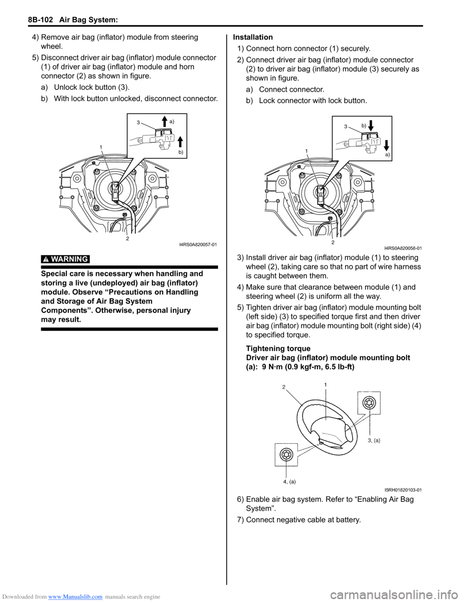
5) Disconnect driver air bag (inflator) module connector (1) of driver air bag (inflator) module and horn
connector (2) as shown in figure.
a) Unlock lock button (3).
b) With lock button unlocked, disconnect connector.
WARNING!
Special care is necessary when handling and
storing a live (undeployed) air bag (inflator)
module. Observe “Precautions on Handling
and Storage of Air Bag System
Components”. Otherwise, personal injury
may result.
Installation
1) Connect horn connector (1) securely.
2) Connect driver air bag (inflator) module connector (2) to driver air bag (inflator) module (3) securely as
shown in figure.
a) Connect connector.
b) Lock connector with lock button.
3) Install driver air bag (inflator) module (1) to steering wheel (2), taking care so t hat no part of wire harness
is caught between them.
4) Make sure that clearance between module (1) and steering wheel (2) is uniform all the way.
5) Tighten driver air bag (inflator) module mounting bolt (left side) (3) to specified torque first and then driver
air bag (inflator) module mounting bolt (right side) (4)
to specified torque.
Tightening torque
Driver air bag (inflator) module mounting bolt
(a): 9 N·m (0.9 kgf-m, 6.5 lb-ft)
6) Enable air bag system. Refer to “Enabling Air Bag System”.
7) Connect negative cable at battery.
1
2
3 a)
b)
I4RS0A820057-01
1
2
3 a)
b)
I4RS0A820058-01
I5RH01820103-01
Page 1167 of 1496

Downloaded from www.Manualslib.com manuals search engine Table of Contents 9- i
9
Section 9
CONTENTS
Body, Cab and Accessories
Precautions ................................................. 9-1
Precautions............................................................. 9-1
Precautions on Body, Cab and Accessories ......... 9-1
Precautions for Body Service ................................ 9-1
Fastener Caution for Body Service ....................... 9-1
Wiring Systems............... ......................... 9A-1
Precautions........................................................... 9A-1
Cautions in Body Electrical System Servicing..... 9A-1
General Description ............................................. 9A-1 Abbreviations ...................................................... 9A-1
Wire / Connector Color Sy mbols ......................... 9A-1
Symbols and Marks ............................................ 9A-2
How to Read Connector Layout Diagram ........... 9A-4
How to Read Connector Codes and Terminal Nos.................................................................... 9A-5
How to Read Ground Point ................................. 9A-7
How to Read Power Supply Diagram.................. 9A-8
How to Read System Circuit Diagram................. 9A-8
Connector Layout Diagram . .............................. 9A-10
Connector Layout Diagram ............................... 9A-10
Engine Compartment .......... .............................. 9A-10
Instrument Panel ............................................... 9A-16
Door, Roof......................................................... 9A-20
Floor .................................................................. 9A-23
Rear .................................................................. 9A-29
Ground Point ...................................................... 9A-30 Ground (earth) Point ......................................... 9A-30
Power Supply Diagram ........ .............................. 9A-31
Power Supply Diagram ....... .............................. 9A-31
Fuses and the Protected Parts ......................... 9A-33
Fuses in Main Fuse Box (RHD) ........................ 9A-33
Fuses in Main Fuse Box (LHD) ......................... 9A-33
Individual Circuit Fuse Box No. 1 ...................... 9A-34
Individual Circuit Fuse Box No. 2 (In J/B) ......... 9A-35
Junction Block (J/B) Connector / Fuse Layout .. 9A-37
Junction Block Inner Circuit (Overview) ............ 9A-38
Junction Block Inner Circuit (Detail) .................. 9A-40
System Circuit Diagram... .................................. 9A-45
System Circuit Diagram .. .................................. 9A-45
A-1 Cranking System Circ uit Diagram .............. 9A-46
A-2 Charging System Circu it Diagram .............. 9A-47
A-3 Ignition System Circu it Diagram ................. 9A-48
A-4 Cooling System Circuit Diagram................. 9A-49 A-5 Engine and A/C Control System Circuit
Diagram........................................................... 9A-50
A-6 A/T Control System Circuit Diagram........... 9A-55
A-7 Immobilizer System Circuit Diagram .......... 9A-57
A-8 Body Control System Circuit Diagram ........ 9A-58
B-1 Windshield Wiper and Washer Circuit Diagram........................................................... 9A-62
B-2 Rear Wiper and Washer Circuit Diagram ... 9A-63
B-3 Rear Defogger Circuit Diagram .................. 9A-64
B-4 Power Window Circuit Diagram .................. 9A-65
B-5 Power Door Lock Circu it Diagram .............. 9A-67
B-6 Power Mirror Circuit Diagram ..................... 9A-69
B-7 Horn Circuit Diagram .................................. 9A-70
B-8 Seat Heater Circuit Diagram....................... 9A-71
B-9 Keyless Start System Circuit Diagram........ 9A-72
C-1 Combination Mete r Circuit Diagram
(Meter)............................................................. 9A-73
C-2 Combination Mete r Circuit Diagram
(Indicator) ........................................................ 9A-74
C-3 Combination Mete r Circuit Diagram
(Warning Light)................................................ 9A-75
D-1 Headlight System Circuit Diagram ............. 9A-77
D-2 Position, Tail and Licence Plate Light System Circuit Diagram .................................. 9A-79
D-3 Front Fog Light System Circuit Diagram .... 9A-80
D-4 Illumination Light System Circuit Diagram .. 9A-81
D-5 Interior Light System Circuit Diagram......... 9A-82
D-6 Turn Signal and Hazard Warning Light System Circuit Diagram .................................. 9A-83
D-7 Brake Light System Circuit Diagram .......... 9A-85
D-8 Back-Up Light System Circuit Diagram ...... 9A-86
D-9 Headlight Beam Leveling System Circuit Diagram........................................................... 9A-87
D-10 Rear Fog Light Circuit Diagram ................ 9A-88
E-1 Heater System Circuit Diagram .................. 9A-89
E-2 Auto A/C System Circuit Diagram .............. 9A-91
F-1 Air-Bag System Circuit Diagram ................. 9A-93
F-2 Anti-Lock Brake System Circuit Diagram.... 9A-95
F-3 Electronic Stab ility Program System
Circuit Diagram .................. ............................. 9A-97
F-4 Power Steering System Circuit Diagram .... 9A-99
G-1 Audio System Circuit Diagram ................. 9A-101
G-2 Multi Information Display / Accessory Socket System Circuit Diagram .................... 9A-102
List of Connector .............................................9A-103
Page 1174 of 1496
Downloaded from www.Manualslib.com manuals search engine 9A-3 Wiring Systems:
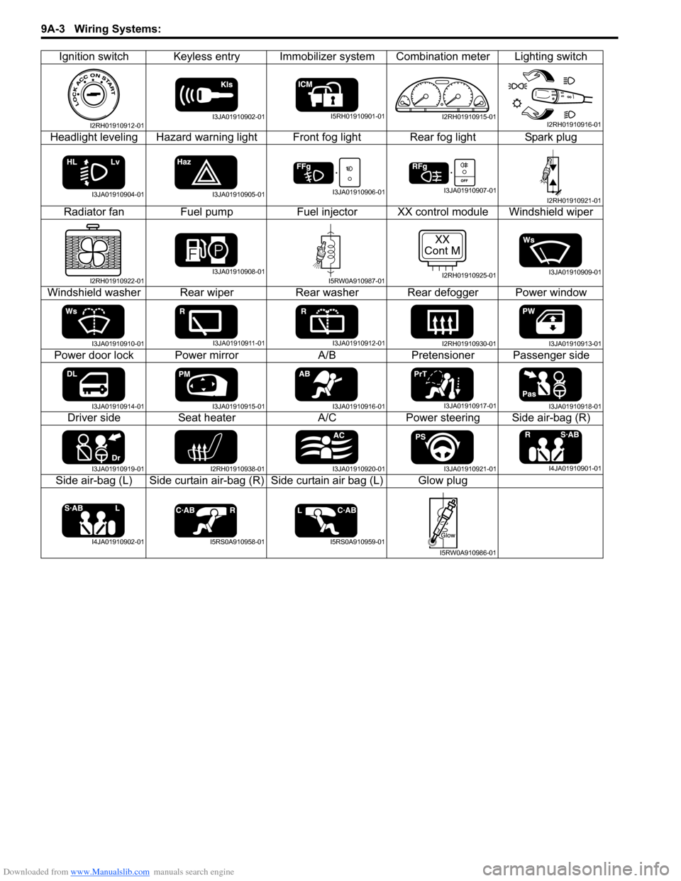
Ignition switch Keyless entry Immobilizer system Combination meter Lighting switch
Headlight leveling Hazard warning light Front fog light Rear fog light Spark plug Radiator fan Fuel pumpFuel injectorXX control module Windshield wiper
Windshield washer Rear wiper Rear washer Rear defogger Power window
Power door lock Power mirror A/BPretensioner Passenger side
Driver side Seat heater A/CPower steering Side air-bag (R)
Side air-bag (L) Side curtain air-bag (R) Side curtain air bag (L) Glow plug
I2RH01910912-01I3JA01910902-01I5RH01910901-01I2RH01910915-01I2RH01910916-01
I3JA01910904-01I3JA01910905-01I3JA01910906-01I3JA01910907-01I2RH01910921-01
I2RH01910922-01I3JA01910908-01I5RW0A910987-01
XX
Cont M
I2RH01910925-01I3JA01910909-01
I3JA01910910-01I3JA01910911-01I3JA01910912-01I2RH01910930-01I3JA01910913-01
I3JA01910914-01I3JA01910915-01I3JA01910916-01I3JA01910917-01I3JA01910918-01
I3JA01910919-01I2RH01910938-01I3JA01910920-01I3JA01910921-01I4JA01910901-01
I4JA01910902-01I5RS0A910958-01I5RS0A910959-01
I5RW0A910986-01
Page 1243 of 1496
Downloaded from www.Manualslib.com manuals search engine Wiring Systems: 9A-72
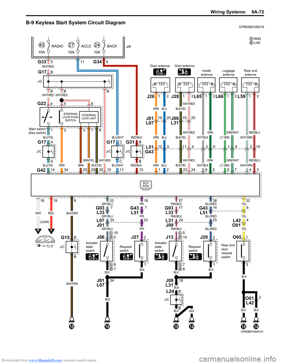
B-9 Keyless Start System Circuit DiagramS7RS0B910E018
BLKBLK
BLK
BLKBLK
YELBLU/REDPNK/BLKPPLGRY/BLU
YELBLU/REDPNK/BLKPPLGRY/BLU
YELBLU/REDPNK/BLKPPLGRY/BLU
G33
KLS
ECM
WHT/RED
WHT/REDWHT/RED
BLU/YEL
WHTRED
ORN
BLU/YEL
"C-3"
WR
G42143420
1819
BLK/ORN
BLK/ORN
9
5
J/B
15A RADIO
40
G348
10A
BACK
24
11
15A
ACC2
27
B
B
B
J/C
G17
B
A
A
J/C
BLU/WHT
BLU/WHT
C
C
J/C
G17
Main switch
(Key switch)
STEERING
LOCK PUSH SWITCH
G22456
1
O051
3
2
BRN29
BRN/YEL
301011RED/BLK
RED/BLK
B
B
J/C
Rear end
door
request
switch
G31
15ORN
ORN
ORN
1BLK/YEL
WHT/RED
378
STEERING
LOCK UNIT
Door antenna
L51
G4312
J01
L07 J261912
BLU
BLU
BLU
2
5
20
WHT/BLK
WHT/BLK6
Inside
antenna
2
12
GRN
GRN
5
9
LT GRN
LT GRN8
Luggage antenna
1
12
GRN/WHT
GRN/WHT
7
8
BLK/YEL
BLK/YEL
BLK/YEL
23
Door antenna
11
J09
L31 J28 L65 L66
WHT/GRN
WHT/GRN4
Rear end
antenna
3
12
RED/BLU
RED/BLU
3
10
L59
1912
WHT/RED
WHT/RED
WHT/RED
24
4
20
G17
B
B
J/C
G15
10
BLK
BLKBLK
32
J292
1
Request
switch
36
1914
J13
Actuator
state
switch
O01 L422
16
BLK
37
1814
J09
L31
J272
1
Request
switch
16
J06
Actuator
state
switch
34
BLK
BLK
33
18
J01
L07
(CAN) RHD
A
LHD
B
AB10
5AB5
10
AB8
7AB7
8
614G43
L5117G03 L337G43 L517G03 L33
423242324L42
O01
L31
J09
L07
J01
B
J/C
B
L24
I7RS0B910924-01
Page 1283 of 1496
Downloaded from www.Manualslib.com manuals search engine Lighting Systems: 9B-1
Body, Cab and Accessories
Lighting Systems
Component Location
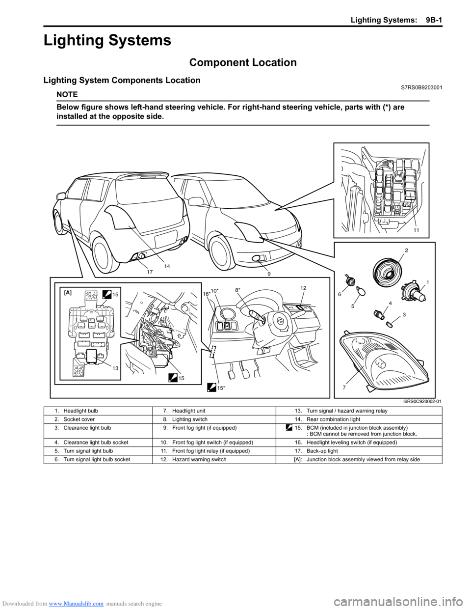
Lighting System Components LocationS7RS0B9203001
NOTE
Below figure shows left-hand steering vehicle. For right-hand steering vehicle, parts with (*) are
installed at the opposite side.
2
1
3
4
6
14
5
7
11
9
15
[A]
1515*
10*
8* 12
13
16*
17
I6RS0C920002-01
1. Headlight bulb 7. Headlight unit 13. Turn signal / hazard warning relay
2. Socket cover 8. Lighting switch 14. Rear combination light
3. Clearance light bulb 9. Front fog light (if equipped)15. BCM (included in junction block assembly)
: BCM cannot be removed from junction block.
4. Clearance light bulb socket 10. Front fog light switch (if equipped) 16. Headlight leveling switch (if equipped)
5. Turn signal light bulb 11. Front fog light relay (if equipped) 17. Back-up light
6. Turn signal light bulb socket 12. Hazard warning switch [A]: Junction block assembly viewed from relay side
Page 1290 of 1496
Downloaded from www.Manualslib.com manuals search engine 9B-8 Lighting Systems:
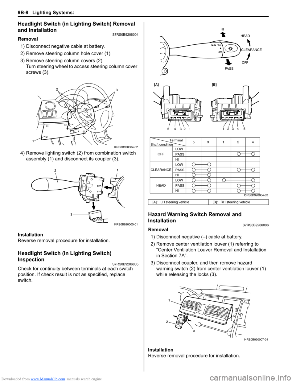
Headlight Switch (in Lighting Switch) Removal
and Installation
S7RS0B9206004
Removal1) Disconnect negative cable at battery.
2) Remove steering column hole cover (1).
3) Remove steering column covers (2). Turn steering wheel to acce ss steering column cover
screws (3).
4) Remove lighting switch (2 ) from combination switch
assembly (1) and disconnect its coupler (3).
Installation
Reverse removal procedure for installation.
Headlight Switch (in Lighting Switch)
Inspection
S7RS0B9206005
Check for continuity between terminals at each switch
position. If check result is not as specified, replace
switch.
Hazard Warning Switch Removal and
Installation
S7RS0B9206006
Removal 1) Disconnect negative (–) cable at battery.
2) Remove center ventilation louver (1) referring to
“Center Ventilation Louver Removal and Installation
in Section 7A”.
3) Disconnect coupler, and then remove hazard warning switch (2) from center ventilation louver (1)
while releasing the locks (3).
Installation
Reverse removal procedure for installation.
1
32
I4RS0B920004-02
1
2
3
I4RS0B920005-01
[A]: LH steering vehicle [B]: RH steering vehicle
Terminal
Shaft condition
OFF 5
3124
LOW
PASS
HI
LOW
PASS
HI LOW
PASS
HI
CLEARANCE
HEAD
HEADCLEARANCE
OFF
HI
PA S S
54321
54321
[A][B]
I5RS0D920004-02
1
2 3
I4RS0B920007-01
Page 1291 of 1496
Downloaded from www.Manualslib.com manuals search engine Lighting Systems: 9B-9
Hazard Warning Switch InspectionS7RS0B9206007
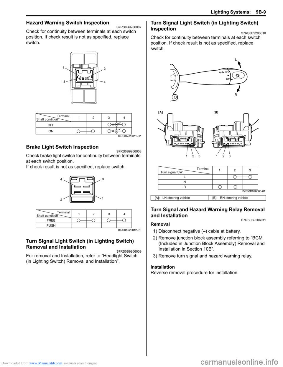
Check for continuity between terminals at each switch
position. If check result is not as specified, replace
switch.
Brake Light Switch InspectionS7RS0B9206008
Check brake light switch for continuity between terminals
at each switch position.
If check result is not as specified, replace switch.
Turn Signal Light Switch (in Lighting Switch)
Removal and Installation
S7RS0B9206009
For removal and Installation, refer to “Headlight Switch
(in Lighting Switch) Removal and Installation”.
Turn Signal Light Switch (in Lighting Switch)
Inspection
S7RS0B9206010
Check for continuity between terminals at each switch
position. If check result is not as specified, replace
switch.
Turn Signal and Hazard Warning Relay Removal
and Installation
S7RS0B9206011
Removal
1) Disconnect negative (–) cable at battery.
2) Remove junction block assembly referring to “BCM (Included in Junction Bl ock Assembly) Removal and
Installation in Section 10B”.
3) Remove turn signal and hazard warning relay.
Installation
Reverse removal procedure for installation.
Terminal
Shaft condition
OFF
ON 12 3 4
1
2
3 4
I4RS0A920011-02
4
2 3
1
Terminal
Shaft condition
FREE
PUSH 12 3 4
I4RS0A920012-01
[A]: LH steering vehicle
[B]: RH steering vehicle
L
R
Terminal
Turn signal SW 3
12
L
N
R 123
123
[A][B]
I5RS0D920006-01
Page 1309 of 1496
Downloaded from www.Manualslib.com manuals search engine Instrumentation / Driver Info. / Horn: 9C-14
Navigation Symptom Diagnosis (If Equipped)S7RS0B9304019
Repair Instructions
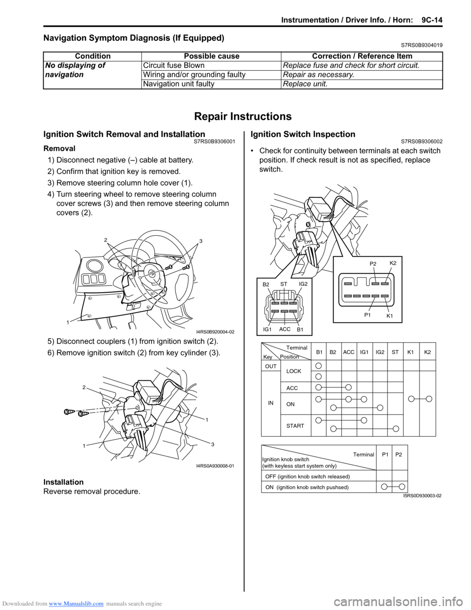
Ignition Switch Removal and InstallationS7RS0B9306001
Removal
1) Disconnect negative (–) cable at battery.
2) Confirm that ignition key is removed.
3) Remove steering column hole cover (1).
4) Turn steering wheel to remove steering column cover screws (3) and then remove steering column
covers (2).
5) Disconnect couplers (1) from ignition switch (2).
6) Remove ignition switch (2) from key cylinder (3).
Installation
Reverse removal procedure.
Ignition Switch InspectionS7RS0B9306002
• Check for continuity between terminals at each switch
position. If check result is not as specified, replace
switch.
Condition Possible cause Correction / Reference Item
No displaying of
navigation Circuit fuse Blown
Replace fuse and check for short circuit.
Wiring and/or grounding faulty Repair as necessary.
Navigation unit faulty Replace unit.
1
32
I4RS0B920004-02
1 1
2
3
I4RS0A930008-01
PositionTerminal
LOCK
ACC
ON
START
OUT
INK2K1ST
IG2
IG1
ACC
B1 B2
Ignition knob switch
(with keyless start system only)
ACC
IG1 IG2
ST
B2
B1 K2
K1
P2
P1
Terminal
OFF (ignition knob switch released) ON (ignition knob switch pushsed)P1 P2
Key
I5RS0D930003-02