2008 SUZUKI SWIFT idle
[x] Cancel search: idlePage 235 of 1496
Downloaded from www.Manualslib.com manuals search engine Engine General Information and Diagnosis: 1A-185
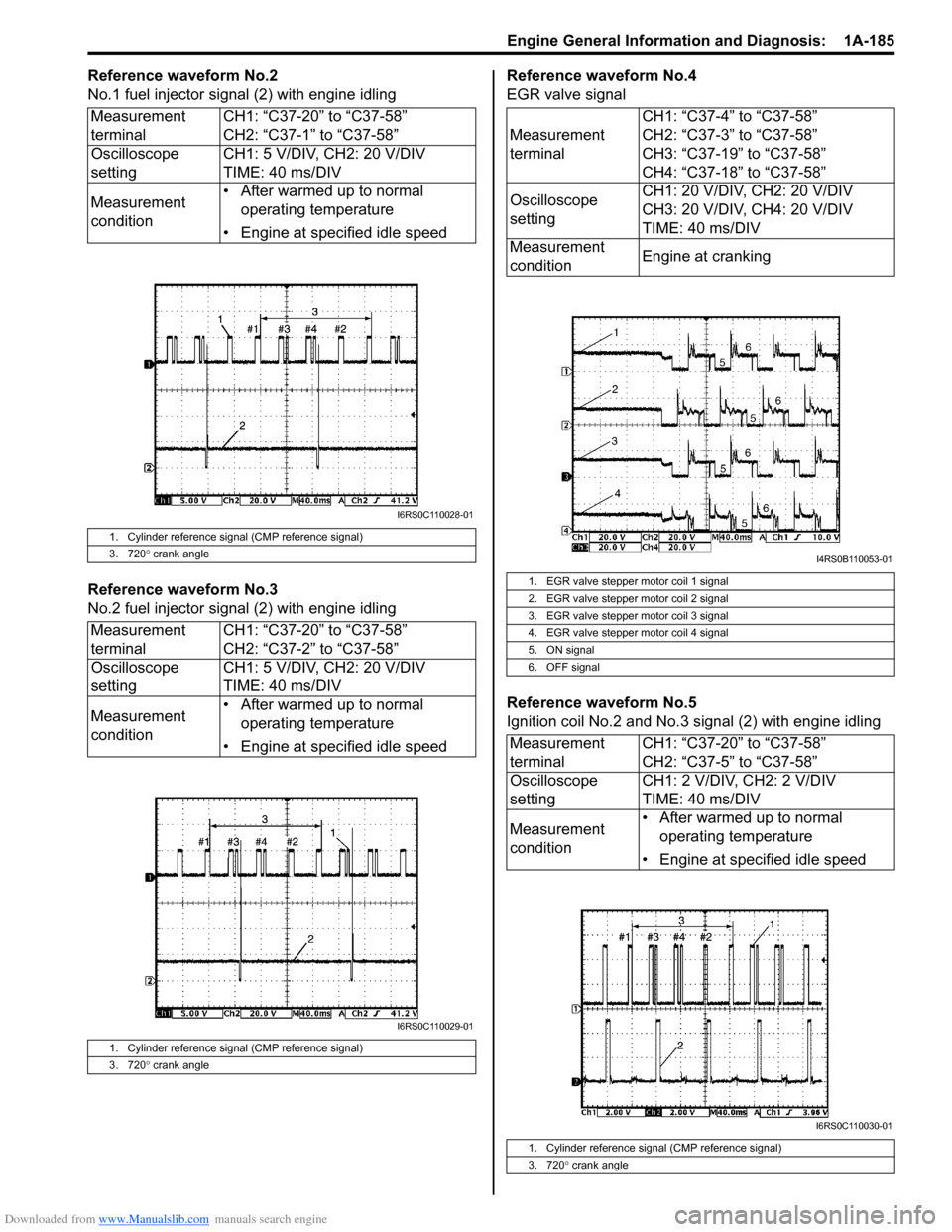
Reference waveform No.2
No.1 fuel injector signal (2) with engine idling
Reference waveform No.3
No.2 fuel injector sig nal (2) with engine idling Reference waveform No.4
EGR valve signal
Reference waveform No.5
Ignition coil No.2 and No.3 signal (2) with engine idling
Measurement
terminal
CH1: “C37-20” to “C37-58”
CH2: “C37-1” to “C37-58”
Oscilloscope
setting CH1: 5 V/DIV, CH2: 20 V/DIV
TIME: 40 ms/DIV
Measurement
condition • After warmed up to normal
operating temperature
• Engine at specified idle speed
1. Cylinder reference signal (CMP reference signal)
3. 720 ° crank angle
Measurement
terminal CH1: “C37-20” to “C37-58”
CH2: “C37-2” to “C37-58”
Oscilloscope
setting CH1: 5 V/DIV, CH2: 20 V/DIV
TIME: 40 ms/DIV
Measurement
condition • After warmed up to normal
operating temperature
• Engine at specified idle speed
1. Cylinder reference signal (CMP reference signal)
3. 720 ° crank angle
I6RS0C110028-01
I6RS0C110029-01
Measurement
terminal CH1: “C37-4” to “C37-58”
CH2: “C37-3” to “C37-58”
CH3: “C37-19” to “C37-58”
CH4: “C37-18” to “C37-58”
Oscilloscope
setting CH1: 20 V/DIV, CH2: 20 V/DIV
CH3: 20 V/DIV, CH4: 20 V/DIV
TIME: 40 ms/DIV
Measurement
condition Engine at cranking
1. EGR valve stepper motor coil 1 signal
2. EGR valve stepper motor coil 2 signal
3. EGR valve stepper motor coil 3 signal
4. EGR valve stepper motor coil 4 signal
5. ON signal
6. OFF signal
Measurement
terminalCH1: “C37-20” to “C37-58”
CH2: “C37-5” to “C37-58”
Oscilloscope
setting CH1: 2 V/DIV, CH2: 2 V/DIV
TIME: 40 ms/DIV
Measurement
condition • After warmed up to normal
operating temperature
• Engine at specified idle speed
1. Cylinder reference signal (CMP reference signal)
3. 720 ° crank angle
I4RS0B110053-01
I6RS0C110030-01
Page 236 of 1496
Downloaded from www.Manualslib.com manuals search engine 1A-186 Engine General Information and Diagnosis:
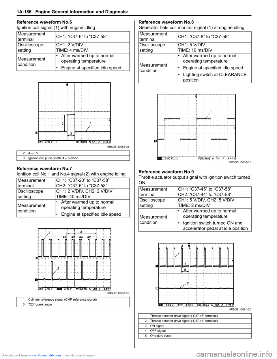
Reference waveform No.6
Ignition coil signal (1) with engine idling
Reference waveform No.7
Ignition coil No.1 and No.4 signal (2) with engine idlingReference waveform No.8
Generator field coil monitor signal (1) at engine idling
Reference waveform No.9
Throttle actuator output signal with ignition switch turned
ON
Measurement
terminal
CH1: “C37-6” to “C37-58”
Oscilloscope
setting CH1: 2 V/DIV
TIME: 4 ms/DIV
Measurement
condition • After warmed up to normal
operating temperature
• Engine at specified idle speed
2. 4 – 6 V
3. Ignition coil pulse width: 4 – 5 msec.
Measurement
terminal CH1: “C37-20” to “C37-58”
CH2: “C37-6” to “C37-58”
Oscilloscope
setting CH1: 2 V/DIV, CH2: 2 V/DIV
TIME: 40 ms/DIV
Measurement
condition • After warmed up to normal
operating temperature
• Engine at specified idle speed
1. Cylinder reference signal (CMP reference signal)
3. 720 ° crank angle
I4RS0B110055-02
I6RS0C110031-01
Measurement
terminal CH1: “C37-8” to “C37-58”
Oscilloscope
setting CH1: 5 V/DIV
TIME: 10 ms/DIV
Measurement
condition • After warmed up to normal
operating temperature
• Engine at specified idle speed
• Lighting switch at CLEARANCE position
Measurement
terminal CH1: “C37-45” to “C37-58”
CH2: “C37-44” to “C37-58”
Oscilloscope
setting CH1: 5 V/DIV, CH2: 5 V/DIV
TIME: 2 ms/DIV
Measurement
condition • After warmed up to normal
operating temperature
• Ignition switch turned ON and accelerator pedal at idle position
1. Throttle actuator drive signal (“C37-45” terminal)
2. Throttle actuator drive signal (“C37-44” terminal)
3. ON signal
4. OFF signal
5. One duty cycle
I5RS0C110016-01
I4RS0B110081-02
Page 237 of 1496
Downloaded from www.Manualslib.com manuals search engine Engine General Information and Diagnosis: 1A-187
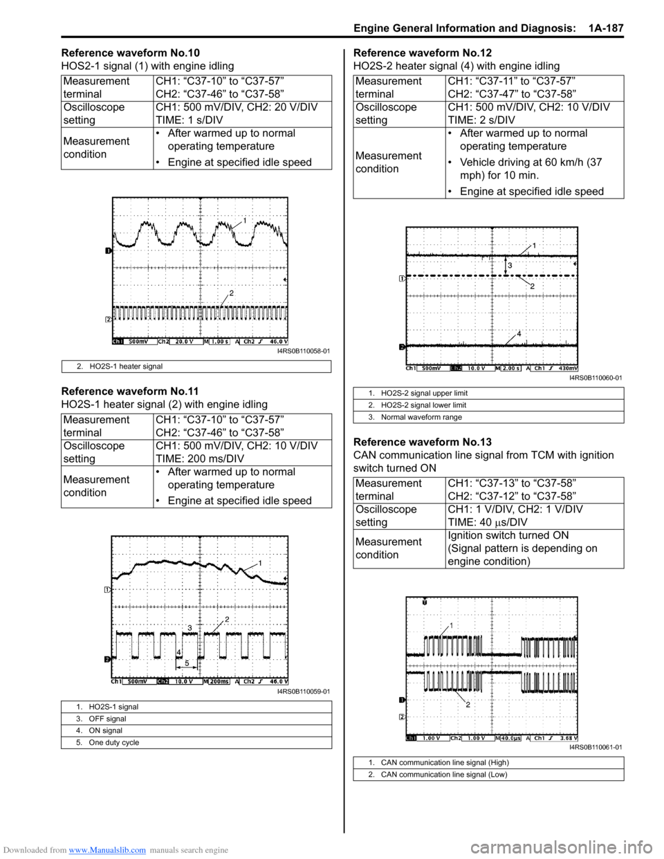
Reference waveform No.10
HOS2-1 signal (1) with engine idling
Reference waveform No.11
HO2S-1 heater signal (2) with engine idlingReference waveform No.12
HO2S-2 heater signal (4) with engine idling
Reference waveform No.13
CAN communication line signal from TCM with ignition
switch turned ON
Measurement
terminal
CH1: “C37-10” to “C37-57”
CH2: “C37-46” to “C37-58”
Oscilloscope
setting CH1: 500 mV/DIV, CH2: 20 V/DIV
TIME: 1 s/DIV
Measurement
condition • After warmed up to normal
operating temperature
• Engine at specified idle speed
2. HO2S-1 heater signal
Measurement
terminal CH1: “C37-10” to “C37-57”
CH2: “C37-46” to “C37-58”
Oscilloscope
setting CH1: 500 mV/DIV, CH2: 10 V/DIV
TIME: 200 ms/DIV
Measurement
condition • After warmed up to normal
operating temperature
• Engine at specified idle speed
1. HO2S-1 signal
3. OFF signal
4. ON signal
5. One duty cycle
I4RS0B110058-01
I4RS0B110059-01
Measurement
terminal CH1: “C37-11” to “C37-57”
CH2: “C37-47” to “C37-58”
Oscilloscope
setting CH1: 500 mV/DIV, CH2: 10 V/DIV
TIME: 2 s/DIV
Measurement
condition • After warmed up to normal
operating temperature
• Vehicle driving at 60 km/h (37 mph) for 10 min.
• Engine at specified idle speed
1. HO2S-2 signal upper limit
2. HO2S-2 signal lower limit
3. Normal waveform range
Measurement
terminal CH1: “C37-13” to “C37-58”
CH2: “C37-12” to “C37-58”
Oscilloscope
setting CH1: 1 V/DIV, CH2: 1 V/DIV
TIME: 40
µs/DIV
Measurement
condition Ignition switch turned ON
(Signal pattern is depending on
engine condition)
1. CAN communication line signal (High)
2. CAN communication line signal (Low)
I4RS0B110060-01
I4RS0B110061-01
Page 238 of 1496
Downloaded from www.Manualslib.com manuals search engine 1A-188 Engine General Information and Diagnosis:
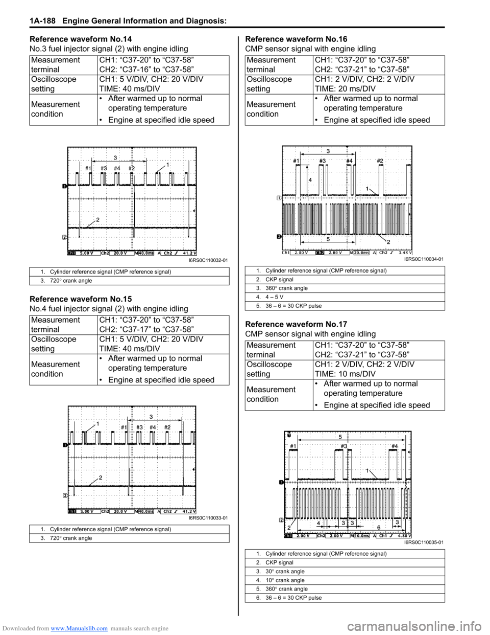
Reference waveform No.14
No.3 fuel injector signal (2) with engine idling
Reference waveform No.15
No.4 fuel injector sig nal (2) with engine idling Reference waveform No.16
CMP sensor signal with engine idling
Reference waveform No.17
CMP sensor signal with engine idling
Measurement
terminal
CH1: “C37-20” to “C37-58”
CH2: “C37-16” to “C37-58”
Oscilloscope
setting CH1: 5 V/DIV, CH2: 20 V/DIV
TIME: 40 ms/DIV
Measurement
condition • After warmed up to normal
operating temperature
• Engine at specified idle speed
1. Cylinder reference signal (CMP reference signal)
3. 720 ° crank angle
Measurement
terminal CH1: “C37-20” to “C37-58”
CH2: “C37-17” to “C37-58”
Oscilloscope
setting CH1: 5 V/DIV, CH2: 20 V/DIV
TIME: 40 ms/DIV
Measurement
condition • After warmed up to normal
operating temperature
• Engine at specified idle speed
1. Cylinder reference signal (CMP reference signal)
3. 720 ° crank angle
I6RS0C110032-01
I6RS0C110033-01
Measurement
terminal CH1: “C37-20” to “C37-58”
CH2: “C37-21” to “C37-58”
Oscilloscope
setting CH1: 2 V/DIV, CH2: 2 V/DIV
TIME: 20 ms/DIV
Measurement
condition • After warmed up to normal
operating temperature
• Engine at specified idle speed
1. Cylinder reference signal (CMP reference signal)
2. CKP signal
3. 360 ° crank angle
4. 4 – 5 V
5. 36 – 6 = 30 CKP pulse
Measurement
terminal CH1: “C37-20” to “C37-58”
CH2: “C37-21” to “C37-58”
Oscilloscope
setting CH1: 2 V/DIV, CH2: 2 V/DIV
TIME: 10 ms/DIV
Measurement
condition • After warmed up to normal
operating temperature
• Engine at specified idle speed
1. Cylinder reference signal (CMP reference signal)
2. CKP signal
3. 30 ° crank angle
4. 10 ° crank angle
5. 360 ° crank angle
6. 36 – 6 = 30 CKP pulse
I6RS0C110034-01
I6RS0C110035-01
Page 239 of 1496
Downloaded from www.Manualslib.com manuals search engine Engine General Information and Diagnosis: 1A-189
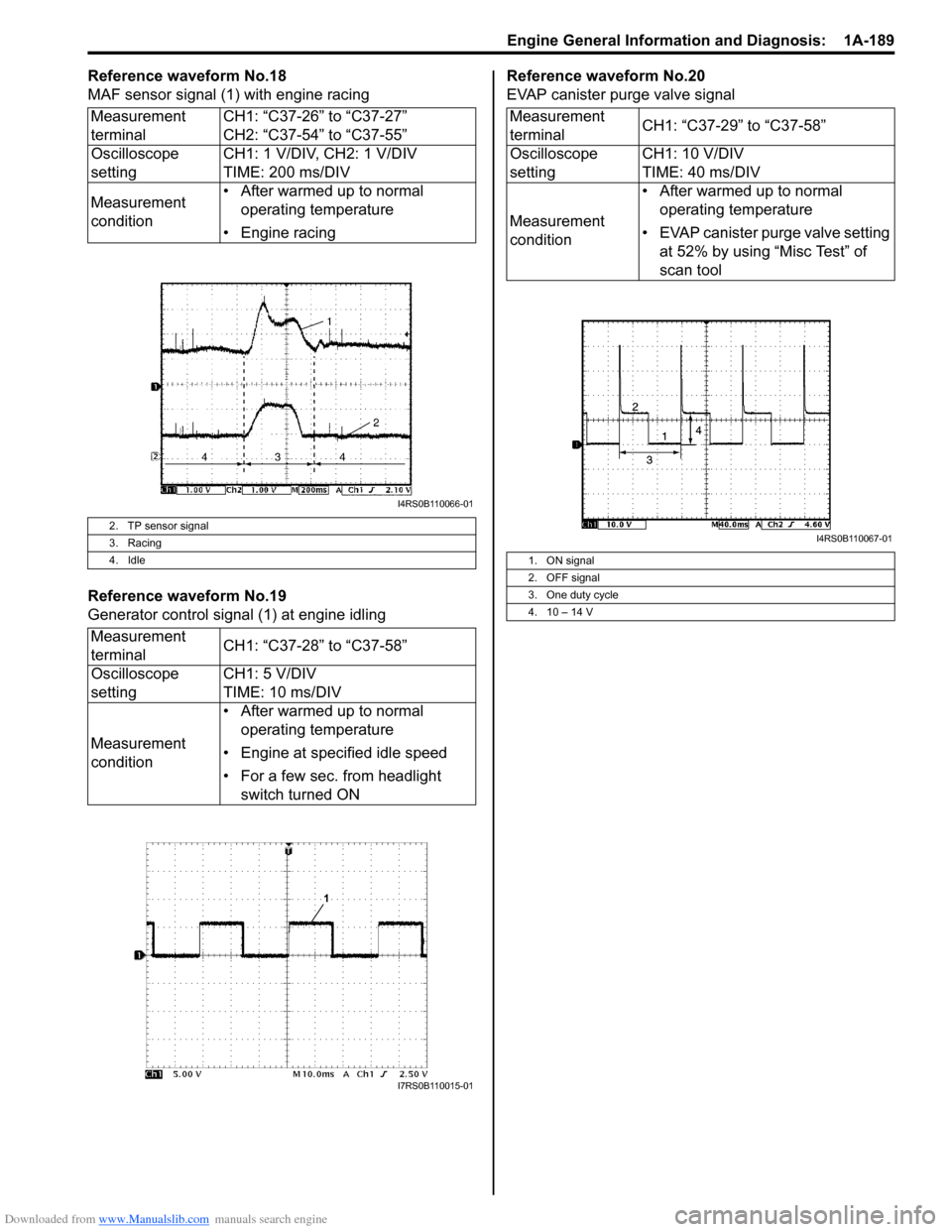
Reference waveform No.18
MAF sensor signal (1) with engine racing
Reference waveform No.19
Generator control signal (1) at engine idlingReference waveform No.20
EVAP canister purge valve signal
Measurement
terminal CH1: “C37-26” to “C37-27”
CH2: “C37-54” to “C37-55”
Oscilloscope
setting CH1: 1 V/DIV, CH2: 1 V/DIV
TIME: 200 ms/DIV
Measurement
condition • After warmed up to normal
operating temperature
• Engine racing
2. TP sensor signal
3. Racing
4. Idle
Measurement
terminal CH1: “C37-28” to “C37-58”
Oscilloscope
setting CH1: 5 V/DIV
TIME: 10 ms/DIV
Measurement
condition • After warmed up to normal
operating temperature
• Engine at specified idle speed
• For a few sec. from headlight switch turned ON
I4RS0B110066-01
I7RS0B110015-01
Measurement
terminal CH1: “C37-29” to “C37-58”
Oscilloscope
setting CH1: 10 V/DIV
TIME: 40 ms/DIV
Measurement
condition • After warmed up to normal
operating temperature
• EVAP canister purge valve setting at 52% by using “Misc Test” of
scan tool
1. ON signal
2. OFF signal
3. One duty cycle
4. 10 – 14 V
I4RS0B110067-01
Page 241 of 1496
Downloaded from www.Manualslib.com manuals search engine Engine General Information and Diagnosis: 1A-191
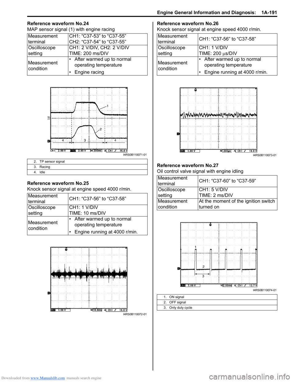
Reference waveform No.24
MAP sensor signal (1) with engine racing
Reference waveform No.25
Knock sensor signal at engine speed 4000 r/min.Reference waveform No.26
Knock sensor signal at engine speed 4000 r/min.
Reference waveform No.27
Oil control valve signal with engine idling
Measurement
terminal
CH1: “C37-53” to “C37-55”
CH2: “C37-54” to “C37-55”
Oscilloscope
setting CH1: 2 V/DIV, CH2: 2 V/DIV
TIME: 200 ms/DIV
Measurement
condition • After warmed up to normal
operating temperature
• Engine racing
2. TP sensor signal
3. Racing
4. Idle
Measurement
terminal CH1: “C37-56” to “C37-58”
Oscilloscope
setting CH1: 1 V/DIV
TIME: 10 ms/DIV
Measurement
condition • After warmed up to normal
operating temperature
• Engine running at 4000 r/min.
I4RS0B110071-01
I4RS0B110072-01
Measurement
terminal CH1: “C37-56” to “C37-58”
Oscilloscope
setting CH1: 1 V/DIV
TIME: 200
µs/DIV
Measurement
condition • After warmed up to normal
operating temperature
• Engine running at 4000 r/min.
Measurement
terminal CH1: “C37-60” to “C37-59”
Oscilloscope
setting CH1: 5 V/DIV
TIME: 2 ms/DIV
Measurement
condition At the moment of the ignition switch
turned on
1. ON signal
2. OFF signal
3. Only duty cycle
I4RS0B110073-01
I4RS0B110074-01
Page 242 of 1496
Downloaded from www.Manualslib.com manuals search engine 1A-192 Engine General Information and Diagnosis:
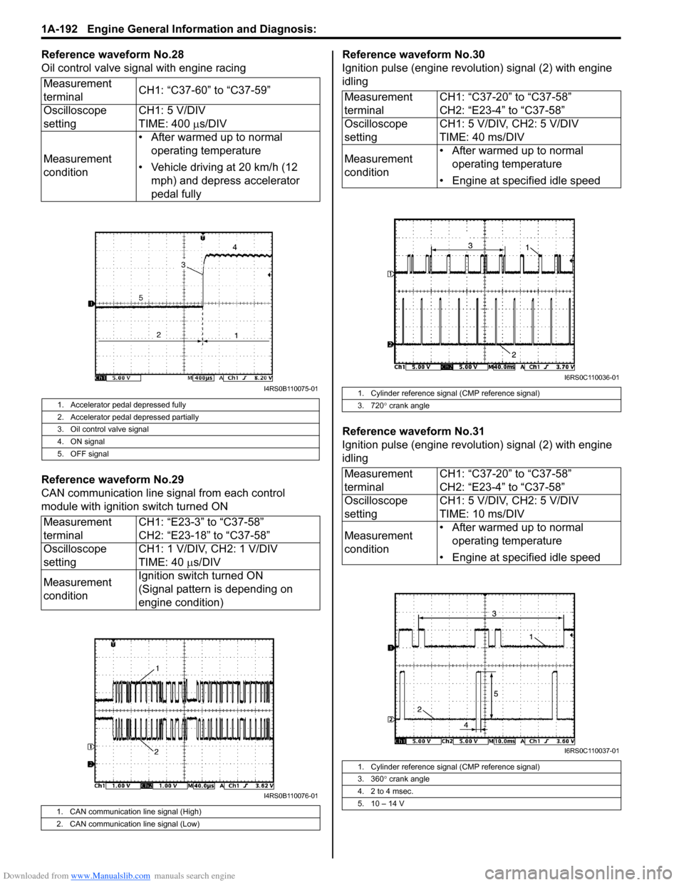
Reference waveform No.28
Oil control valve signal with engine racing
Reference waveform No.29
CAN communication line signal from each control
module with ignition switch turned ONReference waveform No.30
Ignition pulse (engine revolution) signal (2) with engine
idling
Reference waveform No.31
Ignition pulse (engine revolution) signal (2) with engine
idling
Measurement
terminal
CH1: “C37-60” to “C37-59”
Oscilloscope
setting CH1: 5 V/DIV
TIME: 400
µs/DIV
Measurement
condition • After warmed up to normal
operating temperature
• Vehicle driving at 20 km/h (12 mph) and depress accelerator
pedal fully
1. Accelerator pedal depressed fully
2. Accelerator pedal depressed partially
3. Oil control valve signal
4. ON signal
5. OFF signal
Measurement
terminal CH1: “E23-3” to “C37-58”
CH2: “E23-18” to “C37-58”
Oscilloscope
setting CH1: 1 V/DIV, CH2: 1 V/DIV
TIME: 40
µs/DIV
Measurement
condition Ignition switch turned ON
(Signal pattern is depending on
engine condition)
1. CAN communication line signal (High)
2. CAN communication line signal (Low)
I4RS0B110075-01
I4RS0B110076-01
Measurement
terminal
CH1: “C37-20” to “C37-58”
CH2: “E23-4” to “C37-58”
Oscilloscope
setting CH1: 5 V/DIV, CH2: 5 V/DIV
TIME: 40 ms/DIV
Measurement
condition • After warmed up to normal
operating temperature
• Engine at specified idle speed
1. Cylinder reference signal (CMP reference signal)
3. 720 ° crank angle
Measurement
terminal CH1: “C37-20” to “C37-58”
CH2: “E23-4” to “C37-58”
Oscilloscope
setting CH1: 5 V/DIV, CH2: 5 V/DIV
TIME: 10 ms/DIV
Measurement
condition • After warmed up to normal
operating temperature
• Engine at specified idle speed
1. Cylinder reference signal (CMP reference signal)
3. 360 ° crank angle
4. 2 to 4 msec.
5. 10 – 14 V
I6RS0C110036-01
I6RS0C110037-01
Page 266 of 1496
Downloaded from www.Manualslib.com manuals search engine 1A-216 Engine General Information and Diagnosis:
Repair Instructions
Idle Speed and IAC Throttle Valve Opening
Inspection
S7RS0B1106001
Before idle speed check, make sure of the following.
• Lead wires and hoses of electronic fuel injection and engine and emission control systems are connected
securely.
• Valve lash is checked according to maintenance schedule.
• Ignition timing is within specification.
• All accessories (wipers, heater, lights, A/C, etc.) are out of service.
• Air cleaner has been properly installed and is in good condition.
• No abnormal air drawn in from air intake system.
After all items are confirmed, check idle speed and IAC
duty as follows.
NOTE
Before starting engine, place transmission
gear shift lever in “Neutral” (shift selector
lever to “P” range for A/T vehicle), and set
parking brake and block drive wheels.
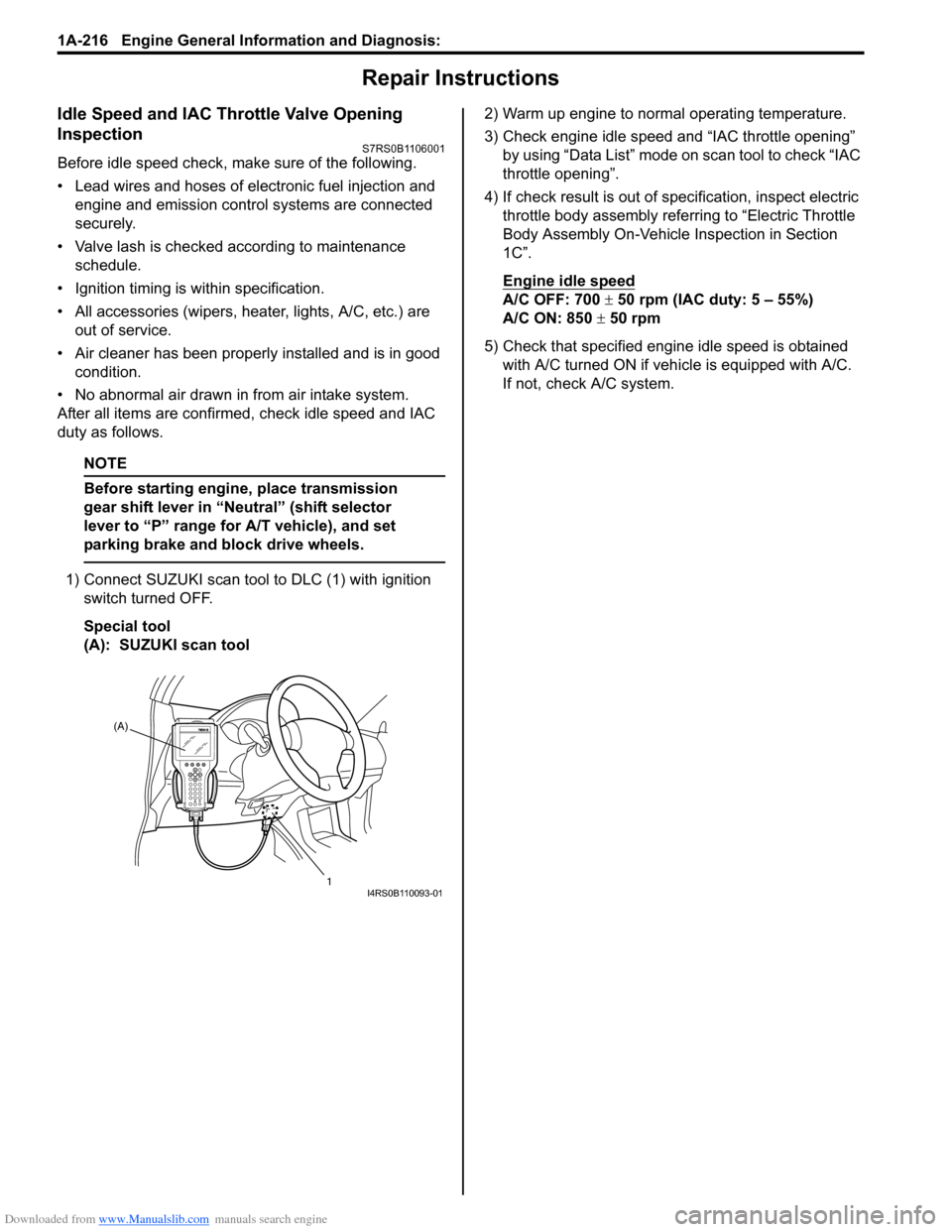
1) Connect SUZUKI scan tool to DLC (1) with ignition
switch turned OFF.
Special tool
(A): SUZUKI scan tool 2) Warm up engine to normal operating temperature.
3) Check engine idle speed and “IAC throttle opening”
by using “Data List” mode on scan tool to check “IAC
throttle opening”.
4) If check result is out of sp ecification, inspect electric
throttle body assembly referring to “Electric Throttle
Body Assembly On-Vehicle Inspection in Section
1C”.
Engine idle speed
A/C OFF: 700 ± 50 rpm (IAC duty: 5 – 55%)
A/C ON: 850 ± 50 rpm
5) Check that specified engine idle speed is obtained with A/C turned ON if vehi cle is equipped with A/C.
If not, check A/C system.
(A)
1
I4RS0B110093-01