2008 SUZUKI SWIFT hold
[x] Cancel search: holdPage 866 of 1496
Downloaded from www.Manualslib.com manuals search engine 5C-14 Clutch:
Special Tools and Equipment
Recommended Service MaterialS7RS0B5308001
NOTE
Required service material is also described in the following.
“Clutch Fluid Pipe and Hose Components”
“Clutch Pedal and Clutch Pedal Bracket Components”
“Clutch Cover, Clutch Disc and Flywheel Components”
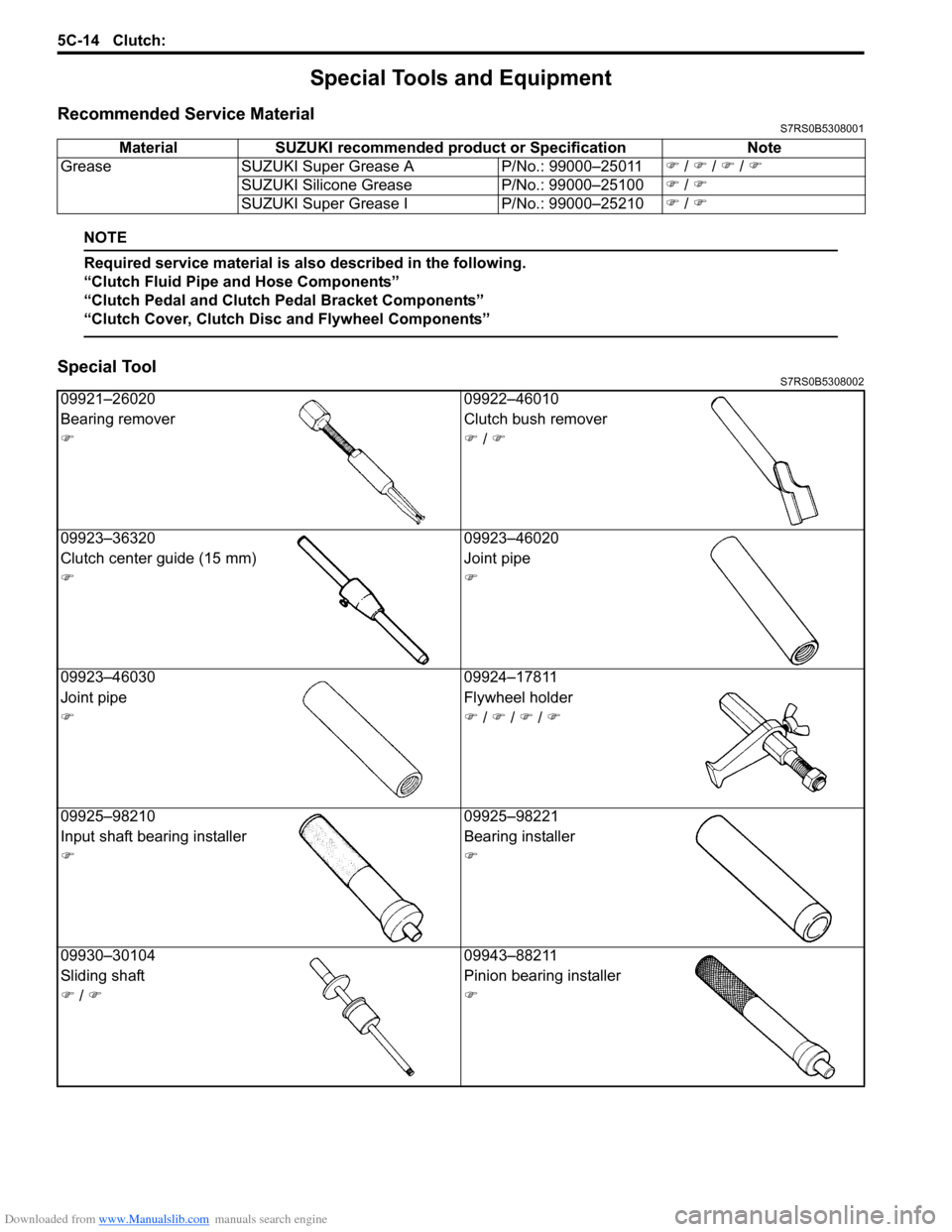
Special ToolS7RS0B5308002
Material SUZUKI recommended product or Specification Note
Grease SUZUKI Super Grease A P/No.: 99000–25011�) / �) / �) / �)
SUZUKI Silicone Grease P/No.: 99000–25100�) / �)
SUZUKI Super Grease I P/No.: 99000–25210�) / �)
09921–26020 09922–46010
Bearing remover Clutch bush remover
�)�) / �)
09923–36320 09923–46020
Clutch center guide (15 mm) Joint pipe
�)�)
09923–46030 09924–17811
Joint pipe Flywheel holder
�)�) / �) / �) / �)
09925–98210 09925–98221
Input shaft bearing inst aller Bearing installer
�)�)
09930–30104 09943–88211
Sliding shaft Pinion bearing installer
�) / �)�)
Page 921 of 1496

Downloaded from www.Manualslib.com manuals search engine Power Assisted Steering System: 6C-39
Reference waveform No.3
Motor output signal 1(1), Motor output signal 2(2), with
engine idling
Steering Wheel Play CheckS7RS0B6304024
• Check steering wheel for looseness or rattle by moving it in its shaft direction and lateral direction.
If found defective, repair or replace.
• Check steering wheel for play, holding vehicle in straight forward condition on the ground with engine
stopped.
If steering wheel play is not within specification,
inspect as follows and replace if found defective.
• Tie-rod end ball stud for wear (Ball stud should move when more than 0.2 N ⋅m (2 kg-cm, 0.44 lb-ft) torque is
applied.)
• Lower ball joint for wear
• Steering shaft joint for wear • Steering pinion or rack gear for wear or breakage
• Each part for looseness
Steering wheel play
“a”
: 0 – 30 mm (0 – 1.18 in.)
Steering Force CheckS7RS0B6304025
1) Place vehicle on level road and set steering wheel at
straight-ahead position.
2) Check if tire inflation pressure is as specified referring to the tire placard.
3) Remove driver air bag (inflator) module referring to “Driver Air Bag (Inflator) Module Removal and
Installation in Section 8B”.
4) Start engine.
5) With engine idling, measure steering force by turning torque wrench.
Steering force
: Less than 6.4 N ⋅m (0.64 kgf-m, 4.6 lb-ft)
6) Install driver air bag (inflator) module referring to “Driver Air Bag (Inflator) Module Removal and
Installation in Section 8B”.
Measurement
terminal
CH1: “E51-1” to vehicle body ground
CH2: “E51-2” to vehicle body ground
Oscilloscope
setting CH1: 5 V/DIV, CH2: 5 V/DIV
TIME: 20
µs/DIV
Measurement
condition • Engine is idling and steering wheel
is kept fully turned to left or right
until it stops
[A]: Steering wheel is kept fully turned left until it stops
[B]: Steering wheel is kept fully turned right until it stops
[C]: 12 V ON
[D]: GND ON
I6RS0B630019-01
I3RM0A630021-01
I3RM0A630022-01
Page 926 of 1496
Downloaded from www.Manualslib.com manuals search engine 6C-44 Power Assisted Steering System:
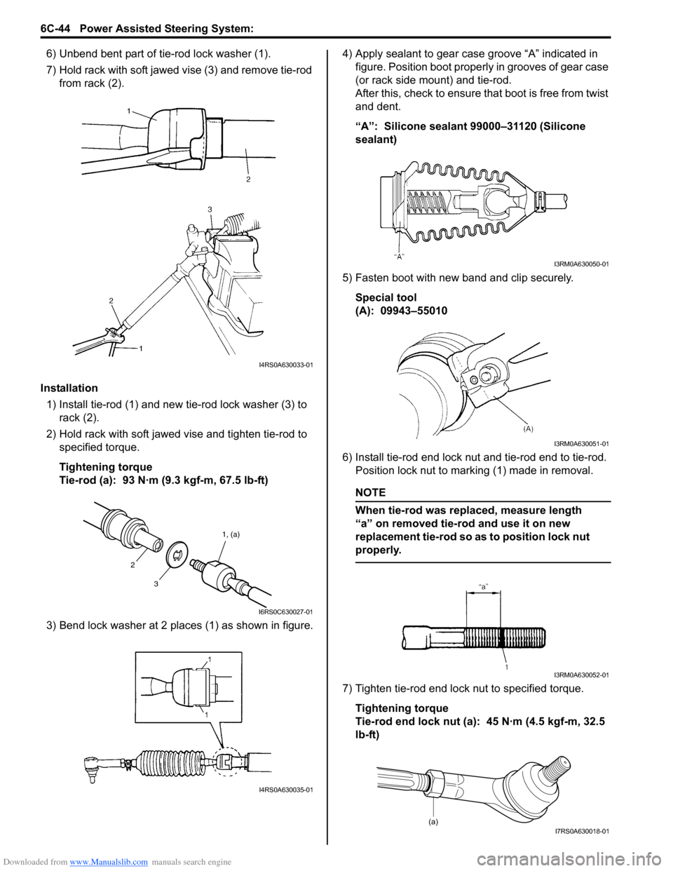
6) Unbend bent part of tie-rod lock washer (1).
7) Hold rack with soft jawed vise (3) and remove tie-rod
from rack (2).
Installation 1) Install tie-rod (1) and new tie-rod lock washer (3) to rack (2).
2) Hold rack with soft jawed vise and tighten tie-rod to specified torque.
Tightening torque
Tie-rod (a): 93 N·m (9.3 kgf-m, 67.5 lb-ft)
3) Bend lock washer at 2 places (1) as shown in figure. 4) Apply sealant to gear case groove “A” indicated in
figure. Position boot properly in grooves of gear case
(or rack side mount) and tie-rod.
After this, check to ensure that boot is free from twist
and dent.
“A”: Silicone sealant 99000–31120 (Silicone
sealant)
5) Fasten boot with new band and clip securely. Special tool
(A): 09943–55010
6) Install tie-rod end lock nut and tie-rod end to tie-rod. Position lock nut to marking (1) made in removal.
NOTE
When tie-rod was replaced, measure length
“a” on removed tie-rod and use it on new
replacement tie-rod so as to position lock nut
properly.
7) Tighten tie-rod end lock nut to specified torque.
Tightening torque
Tie-rod end lock nut (a): 45 N·m (4.5 kgf-m, 32.5
lb-ft)
I4RS0A630033-01
3 1, (a)
2
I6RS0C630027-01
I4RS0A630035-01
I3RM0A630050-01
I3RM0A630051-01
I3RM0A630052-01
(a)I7RS0A630018-01
Page 927 of 1496
Downloaded from www.Manualslib.com manuals search engine Power Assisted Steering System: 6C-45
8) Install steering gear case assembly referring to “Steering Gear Case Assembly Removal and
Installation”.
Steering Rack Plunger Removal and InstallationS7RS0B6306009
Removal
1) Remove gear case assembly referring to “Steering
Gear Case Assembly Removal and Installation”.
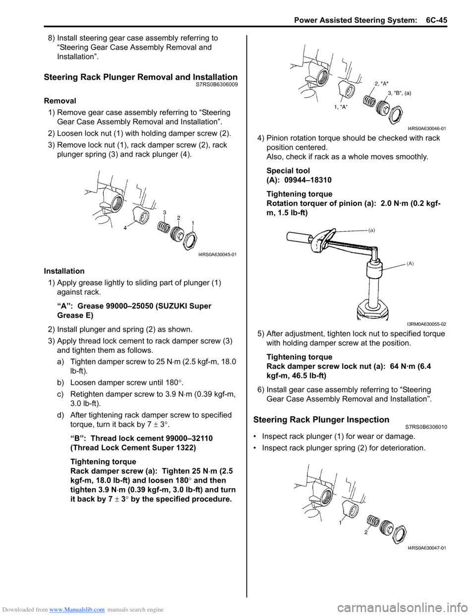
2) Loosen lock nut (1) with holding damper screw (2).
3) Remove lock nut (1), rack damper screw (2), rack plunger spring (3) and rack plunger (4).
Installation 1) Apply grease lightly to sliding part of plunger (1) against rack.
“A”: Grease 99000–25050 (SUZUKI Super
Grease E)
2) Install plunger and spring (2) as shown.
3) Apply thread lock cement to rack damper screw (3)
and tighten them as follows.
a) Tighten damper screw to 25 N ⋅m (2.5 kgf-m, 18.0
lb-ft).
b) Loosen damper screw until 180 °.
c) Retighten damper screw to 3.9 N ⋅m (0.39 kgf-m,
3.0 lb-ft).
d) After tightening rack damper screw to specified torque, turn it back by 7 ± 3°.
“B”: Thread lock cement 99000–32110
(Thread Lock Cement Super 1322)
Tightening torque
Rack damper screw (a): Tighten 25 N ⋅m (2.5
kgf-m, 18.0 lb-ft) and loosen 180° and then
tighten 3.9 N ⋅m (0.39 kgf-m, 3.0 lb-ft) and turn
it back by 7 ± 3° by the specified procedure. 4) Pinion rotation torque should be checked with rack
position centered.
Also, check if rack as a whole moves smoothly.
Special tool
(A): 09944–18310
Tightening torque
Rotation torquer of pinion (a): 2.0 N·m (0.2 kgf-
m, 1.5 lb-ft)
5) After adjustment, tighten lo ck nut to specified torque
with holding damper screw at the position.
Tightening torque
Rack damper screw lock nut (a): 64 N·m (6.4
kgf-m, 46.5 lb-ft)
6) Install gear case assembly referring to “Steering Gear Case Assembly Re moval and Installation”.
Steering Rack Plunger InspectionS7RS0B6306010
• Inspect rack plunger (1) for wear or damage.
• Inspect rack plunger spring (2) for deterioration.
I4RS0A630045-01
I4RS0A630046-01
I3RM0A630055-02
I4RS0A630047-01
Page 973 of 1496
Downloaded from www.Manualslib.com manuals search engine Air Conditioning System: Manual Type 7B-25
Evaporator Thermistor (Evaporator
Temperature Sensor) Removal and Installation
S7RS0B7216008
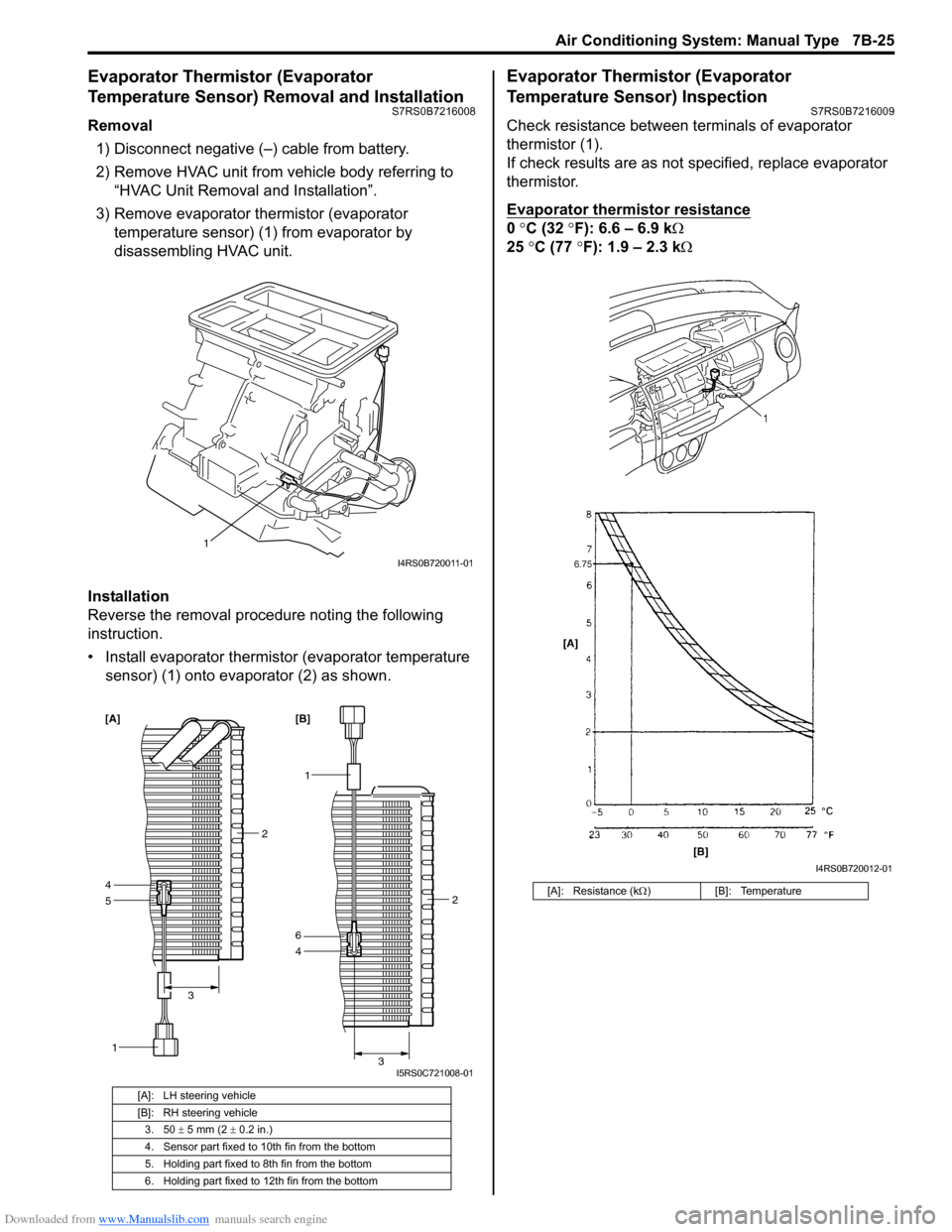
Removal1) Disconnect negative (–) cable from battery.
2) Remove HVAC unit from vehicle body referring to “HVAC Unit Removal and Installation”.
3) Remove evaporator thermistor (evaporator temperature sensor) (1) from evaporator by
disassembling HVAC unit.
Installation
Reverse the removal procedure noting the following
instruction.
• Install evaporator thermistor (evaporator temperature sensor) (1) onto evaporator (2) as shown.
Evaporator Thermistor (Evaporator
Temperature Sensor) Inspection
S7RS0B7216009
Check resistance between terminals of evaporator
thermistor (1).
If check results are as not specified, replace evaporator
thermistor.
Evaporator thermistor resistance
0 °C (32 °F): 6.6 – 6.9 k Ω
25 °C (77 °F): 1.9 – 2.3 kΩ
[A]: LH steering vehicle
[B]: RH steering vehicle
3. 50 ± 5 mm (2 ± 0.2 in.)
4. Sensor part fixed to 10th fin from the bottom
5. Holding part fixed to 8th fin from the bottom
6. Holding part fixed to 12th fin from the bottom
1
I4RS0B720011-01
5
1
4
2
3
[A]
1
4 2
3
6 [B]
I5RS0C721008-01
[A]: Resistance (k Ω) [B]: Temperature
I4RS0B720012-01
Page 981 of 1496

Downloaded from www.Manualslib.com manuals search engine Air Conditioning System: Manual Type 7B-33
Special Tools and Equipment
Recommended Service MaterialS7RS0B7218001
NOTE
Required service material is also described in the following.
“Precautions on Servicing A/C System”
Special ToolS7RS0B7218002
Material SUZUKI recommended product or Specification Note
Compressor oil MATSUSHITADEN KI GU10 P/No.: 99000–99015–
00A �)
/ �)
Silicon sealant SUZUKI SILICON SEALANT KE-
347W (100g) P/No.: 99000–34220
�)
09900–06107 09990–86012
Snap ring pliers (opening
type) Gas leak detector
�) / �) / �) / �) This kit includes following
items. 1. Gas leak detector,
2. Instruction manual, 3.
Filter, 4. Sensor, 5. Dri-sell
battery (size D)�) / �)
09991–06310
Armature plate holder
�) / �)
1 2
3 4
5
Page 1041 of 1496
Downloaded from www.Manualslib.com manuals search engine Air Bag System: 8B-3
• Never attempt disassembly of the air bag (inflator) modules.
• If any abnormality is found, be sure to replace it with
new one as an assembly.
• When an abnormality is noted as existing in the live (undeployed) air bag (inflator) module, be sure to
deploy it before discarding it.
• When grease, cleaning agent, oil, water, etc., got on the air bag (inflator) modules (driver, passenger, side
of both sides and curtain of both sides), wipe it off
immediately with a dry cloth.
• If air bag (inflator) module was dropped from a height of 90 cm (3 ft) or more, it should be replaced with a
new one as an assembly.
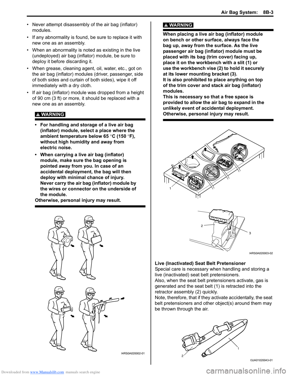
WARNING!
• For handling and storage of a live air bag (inflator) module, select a place where the
ambient temperature below 65 °C (150 ° F),
without high humidity and away from
electric noise.
• When carrying a live air bag (inflator) module, make sure the bag opening is
pointed away from you. In case of an
accidental deployment, the bag will then
deploy with minimal chance of injury.
Never carry the air bag (inflator) module by
the wires or connector on the underside of
the module.
Otherwise, personal injury may result.
WARNING!
When placing a live air bag (inflator) module
on bench or other surface, always face the
bag up, away from the surface. As the live
passenger air bag (inflator) module must be
placed with its bag (trim cover) facing up,
place it on the workbench with a slit (1) or
use the workbench vise (2) to hold it securely
at its lower mounting bracket (3).
It is also prohibited to place anything on top
of the trim cover and stack air bag (inflator)
modules.
This is necessary so that a free space is
provided to allow the air bag to expand in the
unlikely event of accidental deployment.
Otherwise, personal injury may result.
Live (Inactivated) Seat Belt Pretensioner
Special care is necessary when handling and storing a
live (inactivated) seat belt pretensioners.
Also, when the seat belt pretensioners activate, gas is
generated and the seat belt (1) is retracted into the
retractor assembly (2) quickly.
Note, therefore, that if they activate accidentally, the seat
belt pretensioners and other object(s) around them may
be thrown through the air.
I4RS0A820002-01
1
2
3
I4RS0A820003-02
I3JA01820043-01
Page 1142 of 1496
Downloaded from www.Manualslib.com manuals search engine 8B-104 Air Bag System:
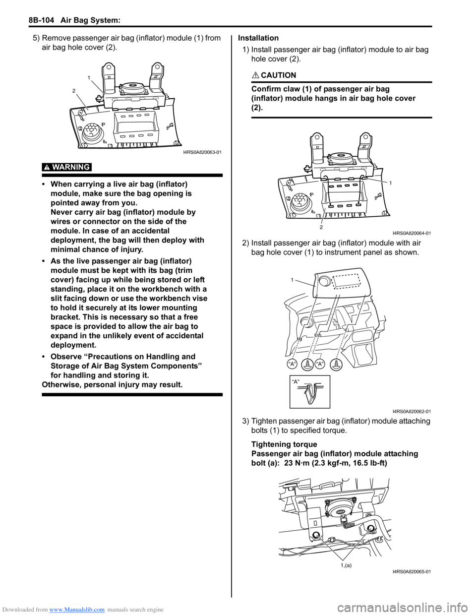
5) Remove passenger air bag (inflator) module (1) from air bag hole cover (2).
WARNING!
• When carrying a live air bag (inflator) module, make sure the bag opening is
pointed away from you.
Never carry air bag (inflator) module by
wires or connector on the side of the
module. In case of an accidental
deployment, the bag will then deploy with
minimal chance of injury.
• As the live passenger air bag (inflator) module must be kept with its bag (trim
cover) facing up while being stored or left
standing, place it on the workbench with a
slit facing down or use the workbench vise
to hold it securely at its lower mounting
bracket. This is necessary so that a free
space is provided to allow the air bag to
expand in the unlikely event of accidental
deployment.
• Observe “Precautions on Handling and Storage of Air Bag System Components”
for handling and storing it.
Otherwise, personal injury may result.
Installation
1) Install passenger air bag (inflator) module to air bag hole cover (2).
CAUTION!
Confirm claw (1) of passenger air bag
(inflator) module hangs in air bag hole cover
(2).
2) Install passenger air bag (inflator) module with air bag hole cover (1) to instrument panel as shown.
3) Tighten passenger air bag (inflator) module attaching bolts (1) to sp ecified torque.
Tightening torque
Passenger air bag (inflator) module attaching
bolt (a): 23 N·m (2.3 kgf-m, 16.5 lb-ft)
1
2
I4RS0A820063-01
2 1I4RS0A820064-01
“A”
“A”“A”
1
I4RS0A820062-01
1,(a)I4RS0A820065-01