Page 1172 of 1496
Downloaded from www.Manualslib.com manuals search engine 9A-1 Wiring Systems:
Body, Cab and Accessories
Wiring Systems
Precautions
Cautions in Body Electrical System ServicingS7RS0B9100001
When servicing the electric systems, observe the cautions described in “Precautions for Electrical Circuit Service in
Section 00” to protect electrical parts and to prevent a fire.
General Description
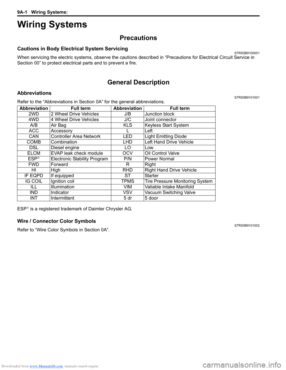
AbbreviationsS7RS0B9101001
Refer to the “Abbreviations in Sect ion 0A” for the general abbreviations.
ESP
® is a registered trademark of Daimler Chrysler AG.
Wire / Connector Color SymbolsS7RS0B9101002
Refer to “Wire Color Sy mbols in Section 0A”.
Abbreviation Full term Abbreviation Full term
2WD 2 Wheel Drive Vehicles J/B Junction block
4WD 4 Wheel Drive Vehicles J/C Joint connectorA/B Air Bag KLS Keyless Start System
ACC Accessory L Left
CAN Controller Area Network LED Light Emitting Diode
COMB Combination LHD Left Hand Drive Vehicle DSL Diesel engine LO Low
ELCM EVAP leak check module OCV Oil Control Valve ESP
®Electronic Stability Program P/N Power Normal
FWD Forward R Right HI High RHD Right Hand Drive Vehicle
IF EQPD If equipped ST Starter IG COIL Ignition coil TPMS Tire Pressure Monitoring System ILL Illumination VIM Valiable Intake Manifold
IND Indicator VSV Vacuum Switching Valve INT Intermittent 5 dr 5 door
Page 1185 of 1496

Downloaded from www.Manualslib.com manuals search engine Wiring Systems: 9A-14
E: Main harness (RHD)
E: Main harness
56
E06E12
E03or
E85
E07
E09
E08
E13
E10
E11E05 E04
E01 E02
E19
7
22
E34E31
E32
E57
E24
(TO C36)
E33
E36
E35
E30
E29
E28
E20
E21
E22
E27
E26
E23
E25E17E56
E18
E14 E15
E55
E
I7RS0B910902-02
No./Color
Connective position No./ColorConnective position
E01/GRY Windshield wiper motor E22/N Front position light (L)
E02/GRY Brake fluid level switch E23/GRY ECM
E03/BLK ABS control module E24/N Engine Harness (To C36)
E04/BLK A/C pressure sensor E25/BLK Wheel speed sensor (FL)
E05/BLK Wheel speed sensor (FR) E26/N Main fuse box
E06/N Side turn signal light (R) E27/BLK Main fuse box
E07/N Front position light (R) E28/BLK Radiator fan relay #1
E08/BLK Head light (R) E29/BLK Radiator fan relay #2
E09/GRY Front turn signal light (R) E30/BLK Radiator fan relay #3
E10/GRN Rear washer motor E31/BLK Starting motor relay
E11/BLU Windshield washer motor E32/BLK Main relay
E12/BLK (IF EQPD) Front fog light (R)
E33/BLK A/T relay
E13/YEL Forward sensor E34/BLK (IF
EQPD) Front fog light relay
E14/BLK Outside air temperature sensor E35/BLK Fuel pump relay
E15/BLK Horn E36/BLK A/C compressor relay
E17/BLK Radiator fan motor E55/- Weld splice
E18/BLK (IF EQPD) Front fog light (L) E56/BLK
(M16A
engine) Throttle actuator control relay
E19/N Side turn signal light (L) E57/BLK Diagnosis connector #1
E20/GRY Front turn signal light (L) E85/BLK (IF
EQPD) ESP
® control module
E21/BLK Headlight (R)
Page 1205 of 1496
Downloaded from www.Manualslib.com manuals search engine Wiring Systems: 9A-34
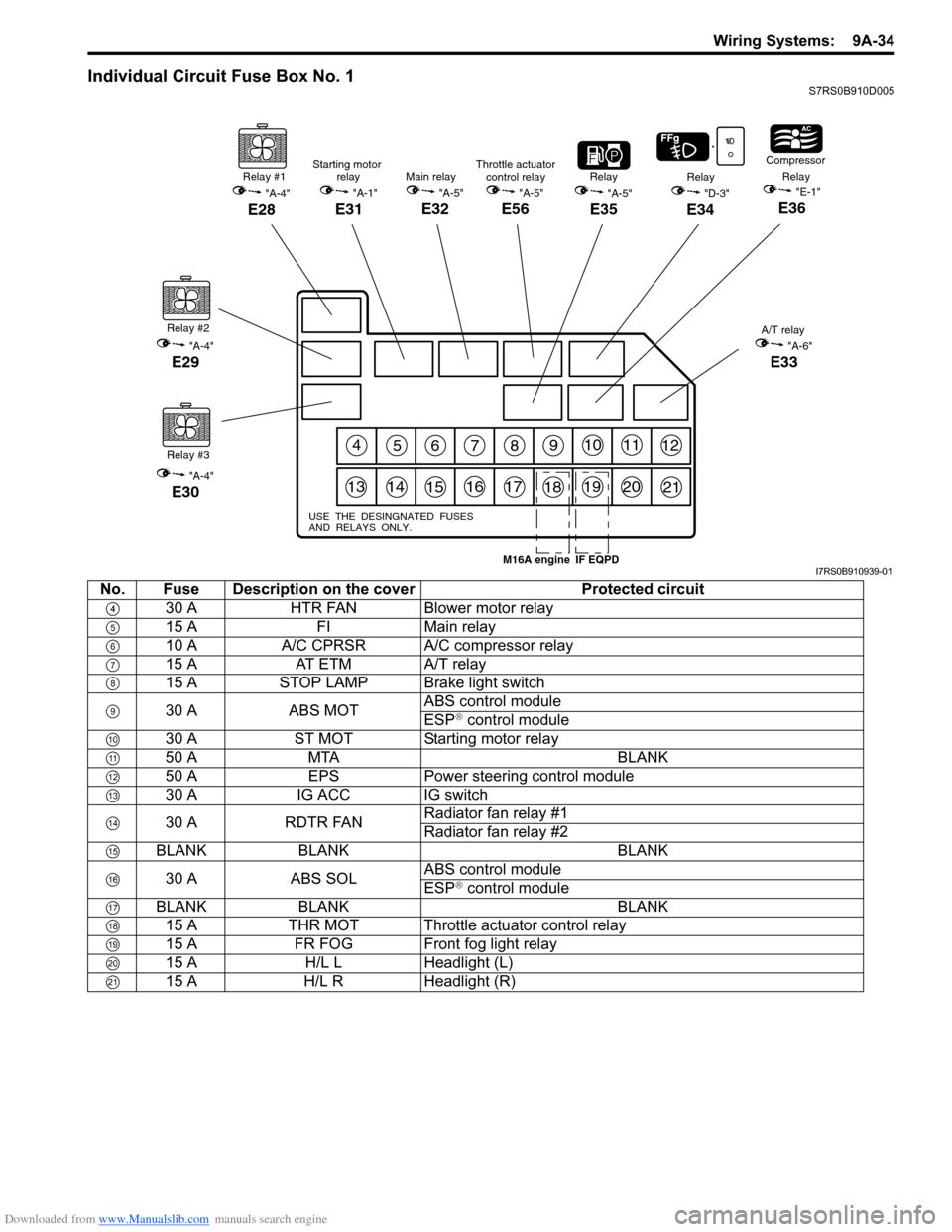
Individual Circuit Fuse Box No. 1S7RS0B910D005
456789101112
131415161718192021
USE THE DESINGNATED FUSES
AND RELAYS ONLY.
Relay #1
"A-4"
E28
Relay #2
"A-4"
E29
Relay #3
"A-4"
E30
"A-5"
E35
RelayRelay
"D-3"
E34
Compressor
Relay"E-1"
E36
A/T relay
"A-6"
E33
Main relay
"A-5"
E32
Starting motor relay
"A-1"
E31
Throttle actuatorcontrol relay
"A-5"
E56
IF EQPDM16A engineI7RS0B910939-01
No. Fuse Description on the cover Protected circuit
30 A HTR FAN Blower motor relay
15 A FIMain relay
10 A A/C CPRSR A/C compressor relay
15 A AT ETM A/T relay
15 A STOP LAMP Brake light switch
30 A ABS MOT ABS control module
ESP
® control module
30 A ST MOT Starting motor relay
50 A MTA BLANK
50 A EPS Power steering control module
30 A IG ACC IG switch
30 A RDTR FAN Radiator fan relay #1
Radiator fan relay #2
BLANK BLANK BLANK
30 A ABS SOL ABS control module
ESP
® control module
BLANK BLANK BLANK 15 A THR MOT Throttle actuator control relay
15 A FR FOG Front fog light relay
15 A H/L L Headlight (L)
15 A H/L R Headlight (R)
Page 1207 of 1496
Downloaded from www.Manualslib.com manuals search engine Wiring Systems: 9A-36
15 AA/BAG A/B SDM
10 A ABSABS control module
ESP
® control module
Steering angle sensor
10 A TAIL COMB switch
BLANK BLANK BLANK 20 A D/L BCM
10 A DIESEL/HID L BLANK
10 A ST SIG Starting motor relay
15 A SEAT HTR Seat heater switch (Driver side)
Seat heater switch (Passenger side)
10 A IG2 SIG Blower motor relay
15 A DEICER/RR FOG COMB switch
15 A RADIO Audio
Auto A/C unit
BCM
COMB meter
DLC
ECM
Interior light
Luggage compartment light
Main switch (Key switch)
Multi information display
KLS ECM
Steering angle sensor
TCM
25 A RR DEF Rear defogger relay
15 A HAZ-HORN Horn relay
Flasher relay
10 A MTA/HID R BLANK
20 A P/WT BLANK
30 A P/W Front power window main switch
Front power window sub switch
Rear power window sub switch (R)
Rear power window sub switch (L)
No. Fuse Description on the cover Protected circuit
Page 1215 of 1496
Downloaded from www.Manualslib.com manuals search engine Wiring Systems: 9A-44
ESP® is a registered trademark of Daimler Chrysler AG.
BCM (J/B side connector)
34
1
2 5
15
14
12
13
10
11
9
8
6
7
17
161821 22
19
20
23
1234578 11 6
12
91034 6 52
1
G33
G32
G34
10
11 12 13 14 15 16 17 18 19 123456789
20
345612K01
23414
3
561214
11
10 157
2113 16
98
6
5
4
3
2
1
7
11
10
9
8
15
14
13
12 16
L04
L06
E41
21
12 34 5 6 78 9
15 16 17 18
1110 12 13 14
1
234
5 678 910
E39
L05
E40
E39 E41E40
BCM G34G33G32 K01 L04 L05 L06J/B
9
3
3
20
3
4
(Continued)
GND (IP)
POWER GND
BCM SIG GND GND (Roof)
GND (POWER)
SIGNAL
GND (FL) SIGNAL
GND (IP) SIGNAL
GND (BCM)
4
4
10
Starter SW
ST RLY COIL
ST SIG 10A36
Individual circuit fuse box No.2
(In J/B)
7
6
BLOWER MOTOR RLY
HTR
HTR Fuse
(30A)
IG2 SIG 10A38
5
7
DOME LP DOOR
DOME LP CONT
21
22
10
9
D/L-IN D/L
D/UL-IND/UL
3
5
2 1
Connector No. / Terminal No.
56
I7RS0B910950-01
Page 1297 of 1496
Downloaded from www.Manualslib.com manuals search engine Instrumentation / Driver Info. / Horn: 9C-2
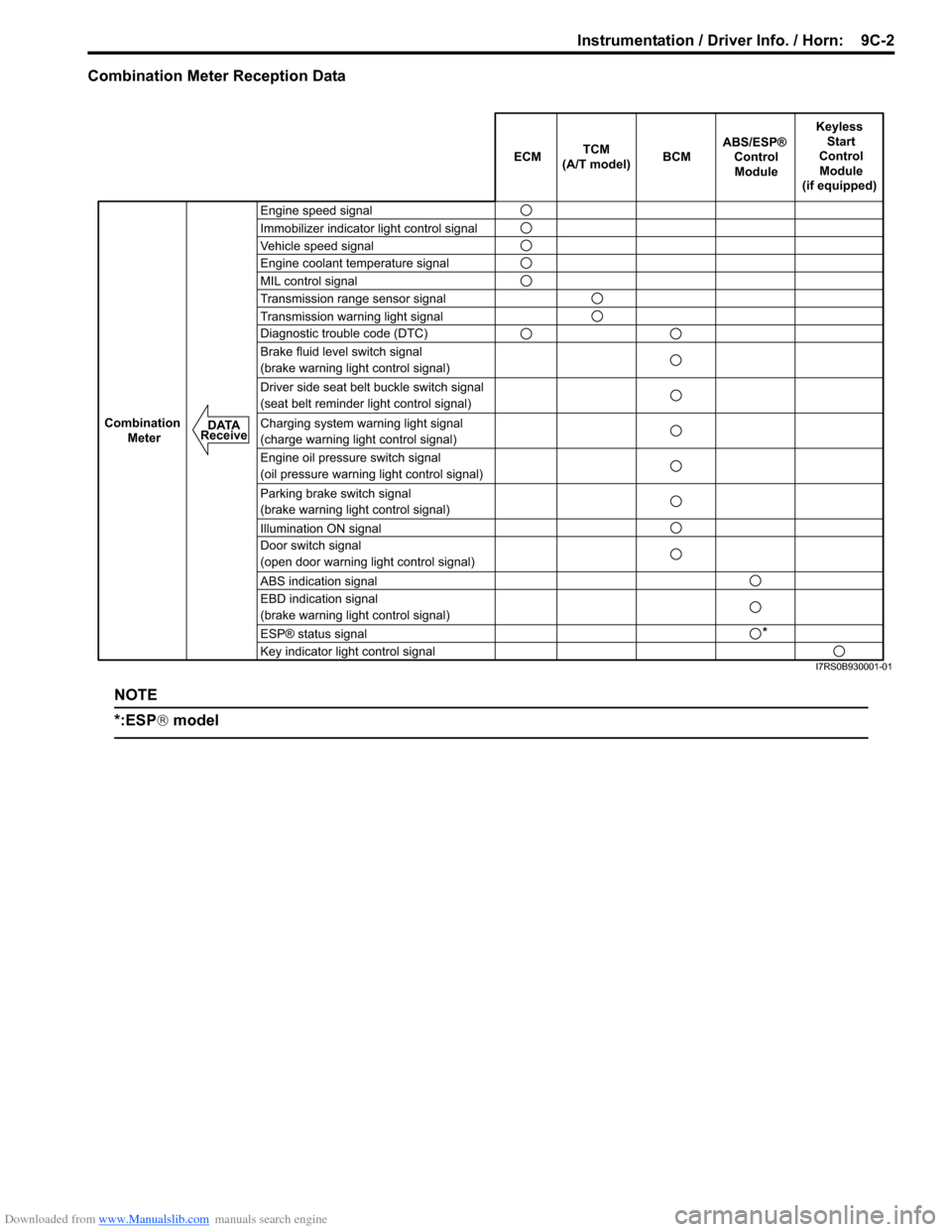
Combination Meter Reception Data
NOTE
*:ESP® model
ECM BCM
Keyless
Start
Control Module
(if equipped)
Combination Meter
TCM
(A/T model)
Engine speed signal
Immobilizer indicator light control signal
Vehicle speed signal
Engine coolant temperature signal
MIL control signal
Transmission range sensor signal
Transmission warning light signal
Diagnostic trouble code (DTC)
Brake fluid level switch signal
(brake warning light control signal)
Driver side seat belt buckle switch signal
(seat belt reminder light control signal)
Charging system warning light signal
(charge warning light control signal)
Engine oil pressure switch signal
(oil pressure warning light control signal)
Parking brake switch signal
(brake warning light control signal)
Illumination ON signal
Door switch signal
(open door warning light control signal)
ABS indication signal
EBD indication signal
(brake warning light control signal)
Key indicator light control signal ABS/ESP®
ControlModule
DATA
Receive
*
ESP® status signal
I7RS0B930001-01
Page 1404 of 1496
Downloaded from www.Manualslib.com manuals search engine 10B-1 Body Electrical Control System:
Control Systems
Body Electrical Control System
Precautions
Precautions in Diagnosing TroubleS7RS0BA200001
• Diagnostic information stored in BCM memory can be cleared as well as checked by using SUZUKI scan tool.
Before using scan tool, read its Operator ’s (Instruction) Manual carefully to have good understanding as to what
functions are available and how to use it.
• Be sure to read “Precautions for Electrical Circuit Serv ice in Section 00” before inspection and observe what is
written there.
• Communication of ECM, TCM (if equipped), ABS/ESP ® control module, steering angle sensor (ESP ® model),
keyless start control module (if equipped), combinatio n meter and BCM is established by CAN (Controller Area
Network). For detail of CAN communication for BCM, refer to “CAN Communication System Description”.
Therefore, handle CAN communication line with care referr ing to “Precaution for CAN Communication System in
Section 00”.
General Description
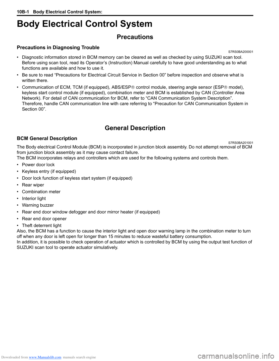
BCM General DescriptionS7RS0BA201001
The Body electrical Control Module (BCM) is incorporated in junction block assembly. Do not attempt removal of BCM
from junction block assembly as it may cause contact failure.
The BCM incorporates relays and controllers which are used for the following systems and controls them.
• Power door lock
• Keyless entry (if equipped)
• Door lock function of keyle ss start system (if equipped)
• Rear wiper
• Combination meter
• Interior light
• Warning buzzer
• Rear end door window defogger and door mirror heater (if equipped)
• Rear end door opener
• Theft deterrent light
Also, the BCM has a function to cause the interior light and open door warning lamp in the combination meter to turn
off when any door is left open for longer than 15 minutes to reduce wasteful battery consumption.
In addition, it is possible to check operation of actuator whic h is controlled by BCM by using the output test function of
SUZUKI scan tool to operate actuator simulatively.
Page 1405 of 1496
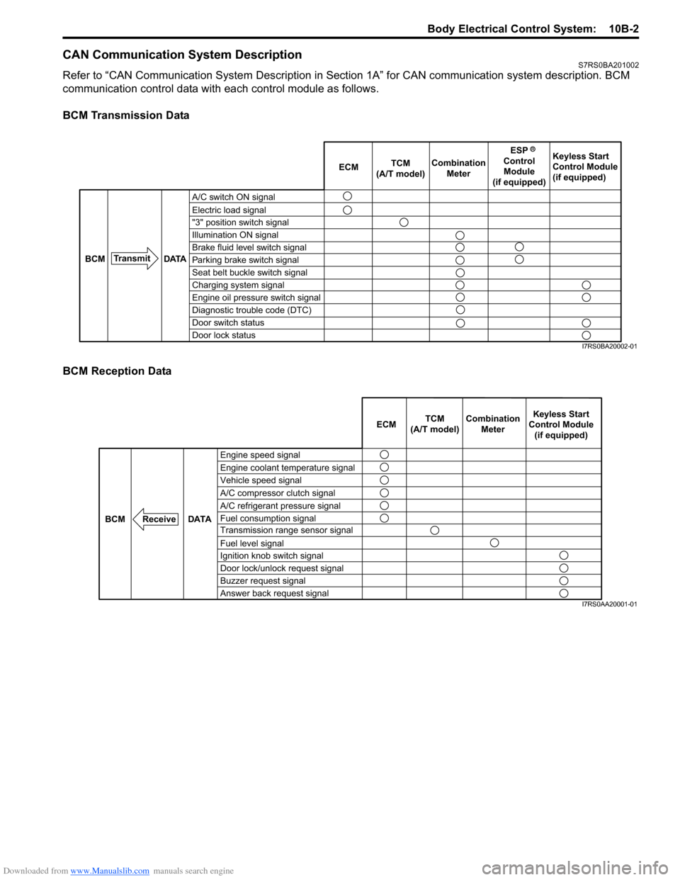
Downloaded from www.Manualslib.com manuals search engine Body Electrical Control System: 10B-2
CAN Communication System DescriptionS7RS0BA201002
Refer to “CAN Communication System Description in Section 1A” for CAN communication system description. BCM
communication control data with ea ch control module as follows.
BCM Transmission Data
BCM Reception Data
A/C switch ON signal
Electric load signal
"3" position switch signal
Illumination ON signal
Brake fluid level switch signal
Parking brake switch signal
Seat belt buckle switch signal
Charging system signal
Engine oil pressure switch signal
Diagnostic trouble code (DTC)
Door switch status
Door lock status ECM
TCM
(A/T model) Combination
Meter Keyless Start
Control Module
(if equipped)
Transmit DATA
BCM
ESP
Control Module
(if equipped)
I7RS0BA20002-01
Engine speed signal
Vehicle speed signal Engine coolant temperature signal
A/C refrigerant pressure signal
Fuel consumption signal A/C compressor clutch signal
Transmission range sensor signal
Fuel level signal
Ignition knob switch signal
Door lock/unlock request signal
Buzzer request signal
Answer back request signal
DATA
BCM
Receive
Combination
Meter
TCM
(A/T model) Keyless Start
Control Module (if equipped)
ECM
I7RS0AA20001-01