2008 SUZUKI SWIFT Vehicle speed signal
[x] Cancel search: Vehicle speed signalPage 691 of 1496

Downloaded from www.Manualslib.com manuals search engine Automatic Transmission/Transaxle: 5A-47
DTC Confirmation Procedure
WARNING!
• When performing a road test, select a place where there is no traffic or possibility of a traffic accident and be very careful during testing to avoid occurrence of an accident.
• Road test should be carried out with 2 persons, a driver and a tester, on a level road.
1) Connect scan tool to DLC with ignition switch OFF.
2) Clear DTCs in TCM memo ry by using scan tool.
3) Start engine and shift select lever to “D” range.
4) Start vehicle and increase vehicle speed to 40 km/h (25 mile/h) or more for 1 minutes.
5) Stop vehicle and turn ignition switch OFF.
6) Repeat Step 3) to 4) one time.
7) Stop vehicle and check DTC.
DTC Troubleshooting Step Action YesNo
1 Was “A/T System Check” performed? Go to Step 2.Go to “A/T System
Check”.
2 Do you have SUZUKI scan tool? Go to Step 3.Go to Step 4.
3 Check transmission range sensor (switch) circuit for
operation
Check by using SUZUKI scan tool:
1) Connect SUZUKI scan tool to DLC with ignition switch
OFF.
2) Turn ignition switch ON and check transmission range signal (P, R, N, D, 3, 2 or L) on display when shifting
select lever to each range.
Is applicable range indicated? Intermittent trouble.
Check for intermittent
referring to “Intermittent
and Poor Connection
Inspection in Section
00”
Go to Step 5.
4 Check transmission range sensor (switch) circuit for
operation
Check by not using SUZUKI scan tool:
1) Turn ignition switch ON.
2) Check voltage at terminals “C35-1”, “C35-7”, “C35-8”,
“C35-18”, “C35-19” and “C35-20” respectively with
select lever shifted to each range.
Taking terminal “C35-19” as an example, is battery
voltage indicated only when se lect lever is shifted to “2”
range and 0 V for other ranges as shown in the following
table.
Check voltage at other terminals likewise, referring to the
following table.
Are check results satisfactory? Intermittent trouble.
Check for intermittent
referring to “Intermittent
and Poor Connection
Inspection in Section
00”.
Go to Step 5.
5 1) Check select cable for adjustment referring to “Select Cable Adjustment”.
Is it adjusted correctly? Go to Step 6.
Adjust.
6 Check transmission range sensor (switch) for
installation position
1) Shift select lever to “N” range.
2) Check that “N” reference line on sensor and needle
direction shaped on lock washer are aligned.
Are they aligned? Go to Step 7.
Adjust.
Page 695 of 1496

Downloaded from www.Manualslib.com manuals search engine Automatic Transmission/Transaxle: 5A-51
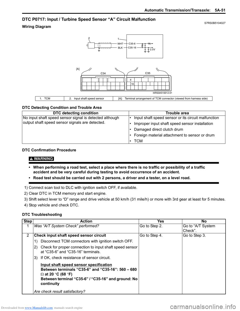
DTC P0717: Input / Turbine Speed Sensor “A” Circuit MalfunctionS7RS0B5104027
Wiring Diagram
DTC Detecting Condition and Trouble Area
DTC Confirmation Procedure
WARNING!
• When performing a road test, select a place where there is no traffic or possibility of a traffic accident and be very careful during testing to avoid occurrence of an accident.
• Road test should be carried out with 2 persons, a driver and a tester, on a level road.
1) Connect scan tool to DLC with ig nition switch OFF, if available.
2) Clear DTC in TCM memory and start engine.
3) Shift select lever to “D” range and drive vehicle at 50 km /h (31 mile/h) or more with 3rd gear at least for 5 minutes.
4) Stop vehicle and check DTC.
DTC Troubleshooting
1. TCM 2. Input shaft speed sensor [A]: Terminal arrangement of TCM connector (viewed from harness side)
DTC detecting condition Trouble area
No input shaft speed sensor signal is detected although
output shaft speed sens or signals are detected. • Input shaft speed sensor or its circuit malfunction
• Improper input shaft speed sensor installation
• Damaged direct clutch drum
• Foreign material attachment to sensor or drum
•TCM
C35-6
2.5VWHT
BLKC35-16
1
2
C34
16
6
C35
[A]
I4RS0A510012-01
Step
Action YesNo
1 Was “A/T System Check” performed? Go to Step 2.Go to “A/T System
Check”.
2 Check input shaft speed sensor circuit
1) Disconnect TCM connectors with ignition switch OFF.
2) Check for proper connection to input shaft speed sensor
at “C35-6” and “C35-16” terminals.
3) If OK, check resistance of sensor circuit.
Input shaft speed sensor specification
Between terminals “C35-6” and “C35-16”: 560 – 680
Ω at 20 °C (68 °F)
Between terminal “C35-6” / “C35-16” and ground: No
continuity
Are check result satisfactory? Go to Step 4. Go to Step 3.
Page 696 of 1496

Downloaded from www.Manualslib.com manuals search engine 5A-52 Automatic Transmission/Transaxle:
DTC P0722: Output Speed Sensor Circuit No SignalS7RS0B5104028
Wiring Diagram
DTC Detecting Condition and Trouble Area
DTC Confirmation Procedure
WARNING!
• When performing a road test, select a place where there is no traffic or possibility of a traffic
accident and be very careful during testing to avoid occurrence of an accident.
• Road test should be carried out with 2 persons, a driver and a tester, on a level road.
3 Inspect input shaft speed sensor
1) Inspect input shaft speed sensor referring to “Input Shaft
Speed Sensor Inspection”.
Is result satisfactory? “WHT” or “BLK” circuit
open or short.
Replace input shaft
speed sensor.
4 Check visually input shaft speed sensor and direct
clutch drum for the following
• No damage
• No foreign material attached
• Correct installation
Are they in good condition? Intermittent trouble or
faulty TCM.
Check for intermittent
referring to “Intermittent
and Poor Connection
Inspection in Section
00”.
If OK, substitute a
known-good TCM and
recheck.
Clean, repair or replace.
Step Action Yes No
I2RH0B510020-01
1. TCM
3. To ECM
2. Output shaft speed sensor [A]: Terminal arrangement of TCM connector (viewed from harness side)
DTC detecting condition Trouble area
No output shaft speed sensor signal is detected although
input shaft speed sensor signal s are detected while vehicle is
running at 5 km/h (3 mile/h) or more in vehicle speed with
“D”, “2” or “L” range. • Output shaft speed sensor or its circuit malfunction
• Damaged sensor gear (driven gear)
• Damaged output shaft speed sensor drive gear
•TCM
IG112V
PPLC35-25
2
C34
25
C35
[A]
1
BLK/RED
BLK/ORN
3
I4RS0B510005-01
Page 697 of 1496

Downloaded from www.Manualslib.com manuals search engine Automatic Transmission/Transaxle: 5A-53
1) Connect scan tool to DLC with ignition switch OFF, if available.
2) Clear DTC in TCM memory and start engine.
3) Shift select lever to “D” range and drive vehicle at 50 km /h (31 mile/h) or more vehicle speed at least for 3 minutes.
4) Stop vehicle and check DTC.
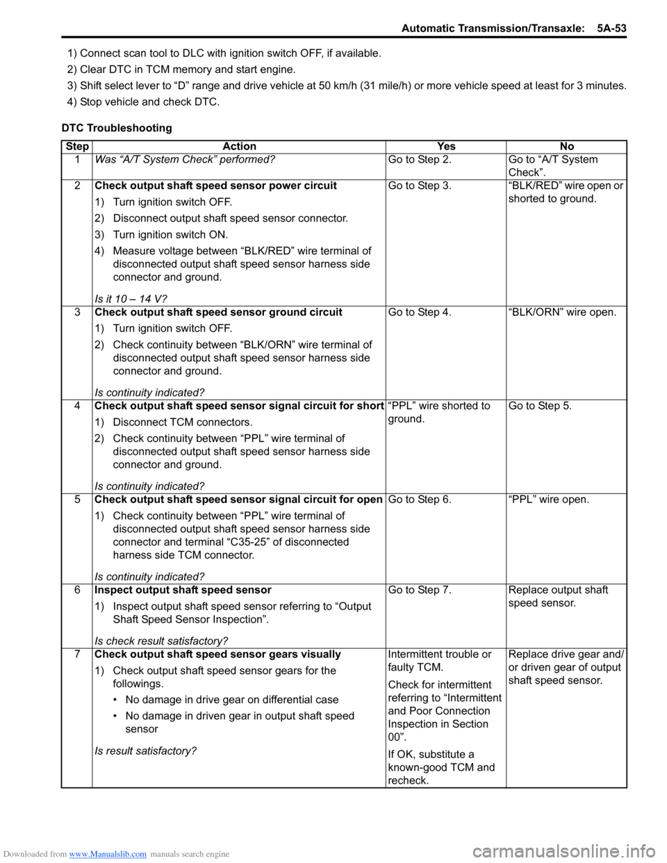
DTC Troubleshooting Step Action Yes No 1 Was “A/T System Check” performed? Go to Step 2. Go to “A/T System
Check”.
2 Check output shaft speed sensor power circuit
1) Turn ignition switch OFF.
2) Disconnect output shaft speed sensor connector.
3) Turn ignition switch ON.
4) Measure voltage between “BLK/RED” wire terminal of
disconnected output shaft speed sensor harness side
connector and ground.
Is it 10 – 14 V? Go to Step 3. “BLK/RED” wire open or
shorted to ground.
3 Check output shaft speed sensor ground circuit
1) Turn ignition switch OFF.
2) Check continuity between “BLK/ORN” wire terminal of
disconnected output shaft speed sensor harness side
connector and ground.
Is continuity indicated? Go to Step 4. “BLK/ORN” wire open.
4 Check output shaft speed sensor signal circuit for short
1) Disconnect TCM connectors.
2) Check continuity between “PPL” wire terminal of
disconnected output shaft speed sensor harness side
connector and ground.
Is continuity indicated? “PPL” wire shorted to
ground.
Go to Step 5.
5 Check output shaft speed sensor signal circuit for open
1) Check continuity between “PPL” wire terminal of
disconnected output shaft speed sensor harness side
connector and terminal “C35-25” of disconnected
harness side TCM connector.
Is continuity indicated? Go to Step 6. “PPL” wire open.
6 Inspect output shaft speed sensor
1) Inspect output shaft speed sensor referring to “Output
Shaft Speed Sensor Inspection”.
Is check result satisfactory? Go to Step 7. Replace output shaft
speed sensor.
7 Check output shaft speed sensor gears visually
1) Check output shaft speed sensor gears for the
followings.
• No damage in drive gear on differential case
• No damage in driven gear in output shaft speed sensor
Is result satisfactory? Intermittent trouble or
faulty TCM.
Check for intermittent
referring to “Intermittent
and Poor Connection
Inspection in Section
00”.
If OK, substitute a
known-good TCM and
recheck.Replace drive gear and/
or driven gear of output
shaft speed sensor.
Page 728 of 1496

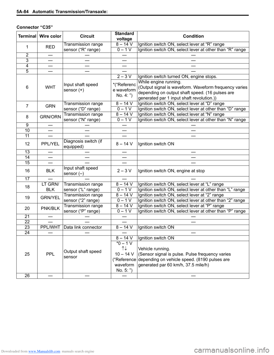
Downloaded from www.Manualslib.com manuals search engine 5A-84 Automatic Transmission/Transaxle:
Connector “C35”
Terminal Wire color Circuit Standard
voltage Condition
1RED Transmission range
sensor (“R” range) 8 – 14 V Ignition switch ON, select lever at “R” range
0 – 1 V Ignition switch ON, select lever at other than “R” range
2— — — —
3— — — —
4— — — —
5— — — —
6WHT Input shaft speed
sensor (+) 2 – 3 V Ignition switch turned ON, engine stops.
*(“Referenc
e waveform No. 4: ”) While engine running.
(Output signal is waveform. Waveform frequency varies
depending on output shaft speed. (16 pulses are
generated par 1 input shaft revolution.))
7GRN Transmission range
sensor (“D” range) 8 – 14 V Ignition switch ON, select lever at “D” range
0 – 1 V Ignition switch ON, select lever at other than “D” range
8 GRN/ORN Transmission range
sensor (“N” range) 8 – 14 V Ignition switch ON, select lever at “N” range
0 – 1 V Ignition switch ON, select lever at other than “N” range
9— — — —
10 — — — — 11 — — — —
12 PPL/YEL Diagnosis switch (if
equipped) 8 – 14 V Ignition switch ON
13 — — — —
14 — — — —
15 — — — —
16 BLK Input shaft speed
sensor (–) 2 – 3 V Ignition switch ON, engine at stop
17 — — — —
18 LT G R N /
BLK Transmission range
sensor (“L” range) 8 – 14 V Ignition switch ON, select lever at “L” range
0 – 1 V Ignition switch ON, select lever at other than “L” range
19 GRN/YEL Transmission range
sensor (“2” range) 8 – 14 V Ignition switch ON, select lever at “2” range
0 – 1 V Ignition switch ON, select lever at other than “2” range
20 PNK/BLK Transmission range
sensor (“P” range) 8 – 14 V Ignition switch ON, select lever at “P” range
0 – 1 V Ignition switch ON, select lever at other than “P” range
21 — — — —
22 — — — —
23 PPL/WHT Data link connector 8 – 14 V Ignition switch ON
24 — — — —
25 PPL Output shaft speed
sensor 8 – 14 V Ignition switch ON
*0 – 1 V ↑↓
10 – 14 V
(“Reference waveform No. 5: ”) Vehicle running.
(Sensor signal is pulse. Pulse frequency varies
depending on vehicle speed. (8190 pulses are
generated par 60 km/h, 37.5 mile/h)
26 — — — —
Page 730 of 1496

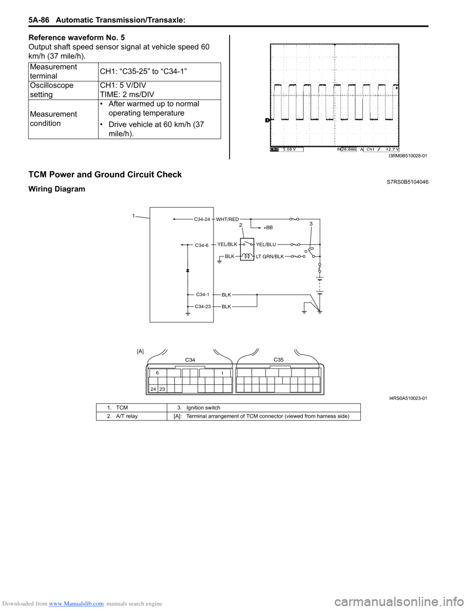
Downloaded from www.Manualslib.com manuals search engine 5A-86 Automatic Transmission/Transaxle:
Reference waveform No. 5
Output shaft speed sensor signal at vehicle speed 60
km/h (37 mile/h).
TCM Power and Ground Circuit CheckS7RS0B5104046
Wiring DiagramMeasurement
terminal
CH1: “C35-25” to “C34-1”
Oscilloscope
setting CH1: 5 V/DIV
TIME: 2 ms/DIV
Measurement
condition • After warmed up to normal
operating temperature
• Drive vehicle at 60 km/h (37 mile/h).
I3RM0B510028-01
BLK
BLK
BLK
C34-1
C34-23
C34-6YEL/BLKYEL/BLU
LT GRN/BLK
+BB
C34-24WHT/RED1
23
6
24 23 1
C34C35
[A]
I4RS0A510023-01
1. TCM
3. Ignition switch
2. A/T relay [A]: Terminal arrangement of TCM connector (viewed from harness side)
Page 884 of 1496

Downloaded from www.Manualslib.com manuals search engine 6C-2 Power Assisted Steering System:
General Description
P/S System DescriptionS7RS0B6301001
This power steering (P/S) system consists of a P/S control module (3), a torque sensor (4), a motor (5). In this system,
the P/S control module determines the level and direction of the assist force for the steering wheel (1) according to the
signals from the torque sensor and vehicle speed signal from ECM. The P/S control module runs the motor so as to
assist the operation of the steering wheel.
The P/S control module diagnoses troubles which may occur in the area including the following components when the
ignition switch is ON and the engine is running. When the P/S control module detects any malfunction, it stops the
motor operation.
• Torque sensor
• Vehicle speed signal
• Engine speed signal
• P/S motor
• P/S control module.
2. Steering column 7. Battery9. ABS/ESP® control module
6. Steering gear case assembly 8. ECM10. Wheel speed sensor (right-front, left-front)
7
3
9
10
10
1
2
4
5
6
8
I7RS0B630001-01
Page 887 of 1496

Downloaded from www.Manualslib.com manuals search engine Power Assisted Steering System: 6C-5
Terminal Arrangement of P/S Control Module Coupler (Viewed from Harness Side)
Diagnostic Information and Procedures
EPS System CheckS7RS0B6304001
WARNING!
Carry out test drive in light traffic area to prevent an accident.
Refer to the following items for the details of each step.Terminal Circuit Terminal Circuit
E49-1 Main power supply for internal memory
and EPS motor E52-9 Ground for torque sensors
E49-2 Ground for P/S control module E52-10 —
E51-1 Motor output 1 E52-11 Serial communication for data link
connector
E51-2 Motor output 2 E52-12 Engine speed signal
E52-1 Ignition switch signal for P/S control
module E52-13 —
E52-2 — E52-14 P/S operation signal (idle up signal)
E52-3 — E52-15 —
E52-4 Vehicle speed signal E52-16 Torque sensor internal failure signal
E52-5 “EPS” warning light E52-17 —
E52-6 Torque sensor signal (Sub) E52-18 Torque sensor signal (Main)
E52-7 — E52-19 Ground for shield wire
E52-8 Main power supply for torque sensor E52-20 5 V reference power supply for torque
sensor
Step
Action YesNo
1 �) Customer complaint analysis
1) Perform customer complaint analysis referring to “Customer Complaint Analysis”.
Was customer complaint analysis performed? Go to Step 2.
Perform customer
complaint analysis.
2 �) DTC check, record and clearance
1) Check for DTC (including pending DTC) referring to “DTC Check”, Record and Clearance.
Is there any DTC(s)? Print DTC or write them
down and clear them by
referring to “DTC
Clearance” and go to
St ep 3 .Go to Step 4.
3 �) Visual inspection
1) Perform visual inspection referring to “Visual Inspection”.
Is there any faulty condition? Repair or replace
malfunction part, and go
to Step 11.
Go to Step 5.
4 �) Visual inspection
1) Perform visual inspection referring to “Visual Inspection”.
Is there any faulty condition? Repair or replace
malfunction part, and go
to Step 11.
Go to Step 8.
5 �) Trouble symptom confirmation
1) Confirm trouble symptom referring to “Trouble Symptom Confirmation”.
Is trouble symptom identified? Go to Step 6.
Go to Step 7.
6 �) Rechecking and record of DTC
1) Recheck for DTC referring to “DTC Check”.
Is there any DTC(s)? Go to Step 9.
Go to Step 8.