2008 SUZUKI SWIFT Enter
[x] Cancel search: EnterPage 572 of 1496
Downloaded from www.Manualslib.com manuals search engine 4E-33 ABS:
Rear Wheel Speed Sensor Removal and
Installation
S7RS0B4506008
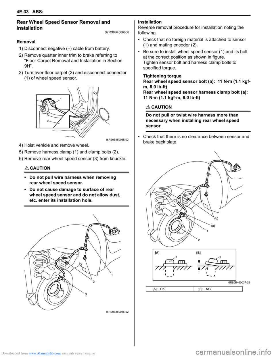
Removal1) Disconnect negative (–) cable from battery.
2) Remove quarter inner trim to brake referring to “Floor Carpet Removal a nd Installation in Section
9H”.
3) Turn over floor carpet (2) and disconnect connector (1) of wheel speed sensor.
4) Hoist vehicle and remove wheel.
5) Remove harness clamp (1) and clamp bolts (2).
6) Remove rear wheel speed sensor (3) from knuckle.
CAUTION!
• Do not pull wire harness when removing rear wheel speed sensor.
• Do not cause damage to surface of rear wheel speed sensor and do not allow dust,
etc. enter its installation hole.
Installation
Reverse removal procedure for installation noting the
following.
• Check that no foreign material is attached to sensor (1) and mating encoder (2).
• Be sure to install wheel speed sensor (1) and its bolt at the correct position as shown in figure.
Tighten sensor bolt and harness clamp bolts to
specified torque.
Tightening torque
Rear wheel speed sensor bolt (a): 11 N·m (1.1 kgf-
m, 8.0 lb-ft)
Rear wheel speed sensor harness clamp bolt (a):
11 N·m (1.1 kgf-m, 8.0 lb-ft)
CAUTION!
Do not pull or twist wire harness more than
necessary when installing rear wheel speed
sensor.
• Check that there is no clearance between sensor and brake back plate.
2
2
1
I6RS0B460035-02
3
2
1
I6RS0B460036-02
[A]: OK [B]: NG
1
(b)
[A][B]
11
(a)
2
I6RS0B460037-02
Page 579 of 1496
Downloaded from www.Manualslib.com manuals search engine Electronic Stability Program: 4F-5
Yaw rate / G sensor
The yaw rate / G sensor consists of the yaw rate (angular velocity in the vehicle turning direction) sensor and right-left
G (acceleration in right-left direction) sensor and is mounted to the P/S controller B/K at the lower part of the center
console. It detects the angular velocity in the vehicle turn ing direction and movement in the right-left direction, and
then it sends that information to ESP ® control module.
Wheel speed sensor
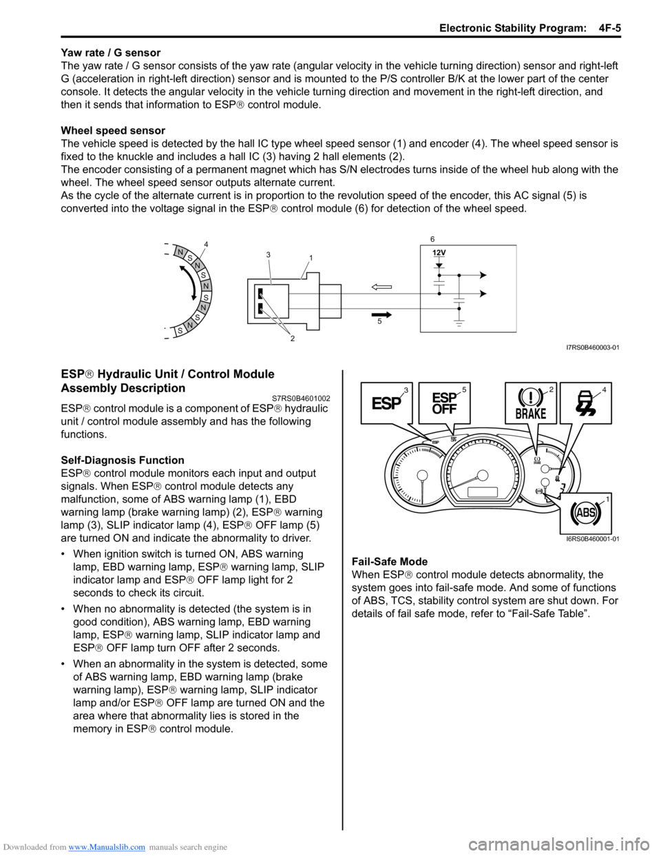
The vehicle speed is detected by the hall IC type wheel speed sensor (1) and encoder (4). The wheel speed sensor is
fixed to the knuckle and includes a hall IC (3) having 2 hall elements (2).
The encoder consisting of a permanent ma gnet which has S/N electrodes turns inside of the wheel hub along with the
wheel. The wheel speed sensor outputs alternate current.
As the cycle of the alternate current is in proportion to the revolution speed of the encoder, this AC signal (5) is
converted into the voltage signal in the ESP ® control module (6) for detection of the wheel speed.
ESP ® Hydraulic Unit / Control Module
Assembly Description
S7RS0B4601002
ESP ® control module is a component of ESP ® hydraulic
unit / control module assembly and has the following
functions.
Self-Diagnosis Function
ESP ® control module monitors each input and output
signals. When ESP ® control module detects any
malfunction, some of ABS warning lamp (1), EBD
warning lamp (brake warning lamp) (2), ESP ® warning
lamp (3), SLIP indicator lamp (4), ESP ® OFF lamp (5)
are turned ON and indicate the abnormality to driver.
• When ignition switch is turned ON, ABS warning lamp, EBD warning lamp, ESP ® warning lamp, SLIP
indicator lamp and ESP ® OFF lamp light for 2
seconds to check its circuit.
• When no abnormality is detected (the system is in good condition), ABS warning lamp, EBD warning
lamp, ESP ® warning lamp, SLIP indicator lamp and
ESP ® OFF lamp turn OFF after 2 seconds.
• When an abnormality in the system is detected, some of ABS warning lamp, EBD warning lamp (brake
warning lamp), ESP ® warning lamp, SLIP indicator
lamp and/or ESP ® OFF lamp are turned ON and the
area where that abnormality lies is stored in the
memory in ESP ® control module. Fail-Safe Mode
When ESP
® control module detects abnormality, the
system goes into fail-safe mode. And some of functions
of ABS, TCS, stability control system are shut down. For
details of fail safe mode, re fer to “Fail-Safe Table”.
S
N
S
N
S
N
N
S
N
S
12V
2
3
1
5
4
6I7RS0B460003-01
3245
1
I6RS0B460001-01
Page 630 of 1496
Downloaded from www.Manualslib.com manuals search engine 4F-56 Electronic Stability Program:
ESP® Hydraulic Unit / Control Module Assembly Removal and InstallationS7RS0B4606037
CAUTION!
Never disassemble ESP ® hydraulic unit / control module assembly loosen blind plug or remove motor.
Performing any of these proh ibited services will affect original performance of ESP ® hydraulic unit /
control module assembly.
Removal
CAUTION!
• Do not give an impact to hydraulic unit.
• Use care not to allow dust to enter hydraulic unit.
• Do not place hydraulic unit on its side or upside down. Handling it in inappropriate
way will affect its original performance.
1) Disconnect negative (–) cable from battery.
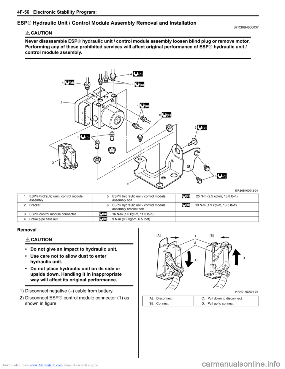
2) Disconnect ESP ® control module connector (1) as
shown in figure.
3 1
(c)
2
(b)
(a)4
(a)
4
5
6
(b)
5
(c)
6
(d)
(d) 4
4
I7RS0B460012-01
1. ESP ® hydraulic unit / control module
assembly 5. ESP
® hydraulic unit / control module
assembly bolt : 25 N
⋅m (2.5 kgf-m, 18.0 lb-ft)
2. Bracket 6. ESP ® hydraulic unit / control module
assembly bracket bolt : 19 N
⋅m (1.9 kgf-m, 13.5 lb-ft)
3. ESP ® control module connector : 16 N ⋅m (1.6 kgf-m, 11.5 lb-ft)
4. Brake pipe flare nut : 9 N ⋅m (0.9 kgf-m, 6.5 lb-ft)
[A]: DisconnectC: Pull down to disconnect
[B]: Connect D: Pull up to connect
21
C D
[A]
[B]
I4RH01450001-01
Page 632 of 1496
Downloaded from www.Manualslib.com manuals search engine 4F-58 Electronic Stability Program:
6) Measure voltage at resistance without wheel rotation.
If voltage is out of specification, check sensor,
mating encoder and their installation conditions.
Voltage at the resistance (115
Ω) without wheel
rotation
680 to 960 mV
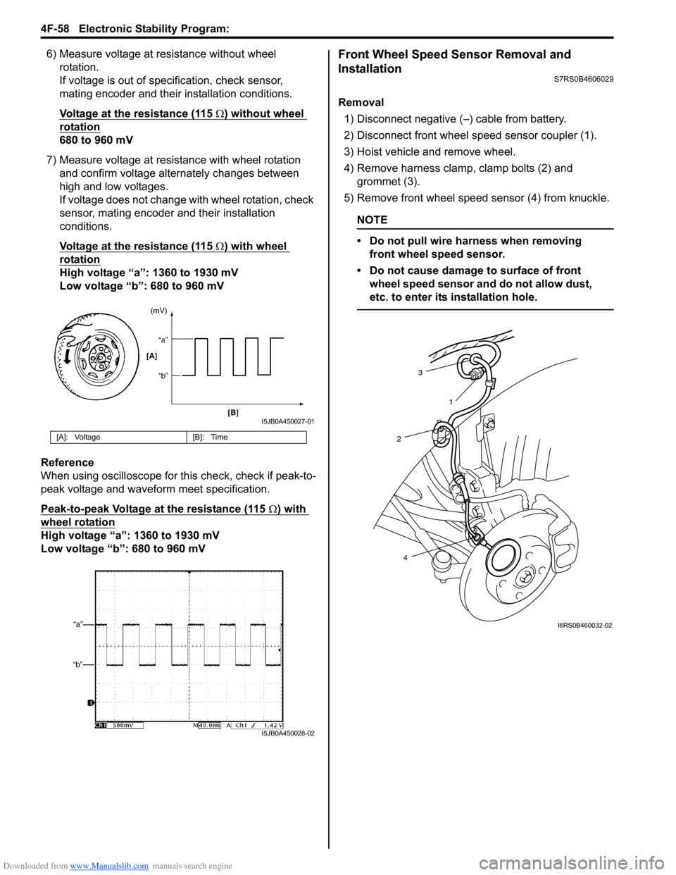
7) Measure voltage at resistance with wheel rotation and confirm voltage alternately changes between
high and low voltages.
If voltage does not change with wheel rotation, check
sensor, mating encoder and their installation
conditions.
Voltage at the resistance (115
Ω) with wheel
rotation
High voltage “a”: 1360 to 1930 mV
Low voltage “b”: 680 to 960 mV
Reference
When using oscilloscope for this check, check if peak-to-
peak voltage and waveform meet specification.
Peak-to-peak Voltage at the resistance (115
Ω) with
wheel rotation
High voltage “a”: 1360 to 1930 mV
Low voltage “b”: 680 to 960 mV
Front Wheel Speed Sensor Removal and
Installation
S7RS0B4606029
Removal
1) Disconnect negative (–) cable from battery.
2) Disconnect front wheel speed sensor coupler (1).
3) Hoist vehicle and remove wheel.
4) Remove harness clamp, clamp bolts (2) and grommet (3).
5) Remove front wheel speed sensor (4) from knuckle.
NOTE
• Do not pull wire harness when removing front wheel speed sensor.
• Do not cause damage to surface of front wheel speed sensor and do not allow dust,
etc. to enter its installation hole.
[A]: Voltage [B]: Time
I5JB0A450027-01
I5JB0A450028-02
3
2
4 1
I6RS0B460032-02
Page 633 of 1496
Downloaded from www.Manualslib.com manuals search engine Electronic Stability Program: 4F-59
Installation
CAUTION!
Do not pull or twist wire harness more than
necessary when installing front wheel speed
sensor.
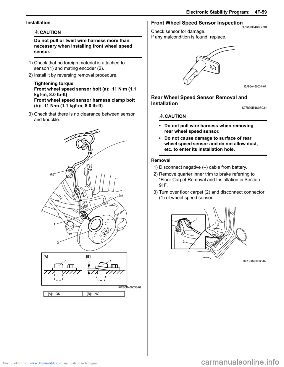
1) Check that no foreign material is attached to sensor(1) and mating encoder (2).
2) Install it by reversing removal procedure.
Tightening torque
Front wheel speed sensor bolt (a): 11 N·m (1.1
kgf-m, 8.0 lb-ft)
Front wheel speed sensor harness clamp bolt
(b): 11 N·m (1.1 kgf-m, 8.0 lb-ft)
3) Check that there is no clearance between sensor and knuckle.
Front Wheel Speed Sensor InspectionS7RS0B4606030
Check sensor for damage.
If any malcondition is found, replace.
Rear Wheel Speed Sensor Removal and
Installation
S7RS0B4606031
CAUTION!
• Do not pull wire harness when removing rear wheel speed sensor.
• Do not cause damage to surface of rear wheel speed sensor and do not allow dust,
etc. to enter its installation hole.
Removal
1) Disconnect negative (–) cable from battery.
2) Remove quarter inner trim to brake referring to
“Floor Carpet Removal and Installation in Section
9H”.
3) Turn over floor carpet (2) and disconnect connector (1) of wheel speed sensor.
[A]: OK [B]: NG
(b)
1
[A][B]
11
2
(a)
I6RS0B460033-02
I5JB0A450031-01
2
2
1
I6RS0B460035-02
Page 645 of 1496
Downloaded from www.Manualslib.com manuals search engine Automatic Transmission/Transaxle: 5A-1
Transmission / Transaxle
Automatic Transmission/Transaxle
Precautions
Precautions in Diagnosing TroubleS7RS0B5100001
• Do not disconnect couplers from TCM, battery cable from battery, TCM ground wire harness from engine or
main fuse before checking the diagnostic information
(DTC, freeze frame data, etc.) stored in TCM memory.
Such disconnection will clea r memorized information
in TCM memory.
• Diagnostic information stored in TCM memory can be cleared as well as checked by using SUZUKI scan
tool or generic scan tool. Before using scan tool, read
its Operator’s (Instruction) Manual carefully to have
good understanding as to what functions are available
and how to use it.
It is indistinguishable wh ich module turns on MIL
because not only ECM but also TCM turns on MIL.
Therefore, check both ECM and TCM for DTC when
MIL lights on.
When checking TCM for DTC, keep in mind that DTC
is displayed on the scan tool as follows depending on
the scan tool used.
– SUZUKI scan tool displays DTC detected by TCM.
– Generic scan tool displays DTC detected by each of ECM and TCM simultaneously.
• Using SUZUKI scan tool the diagnostic information stored in TCM memory can be checked and cleared
as well. Before its use, be sure to read Operator’s
Manual supplied with it carefully to have good
understanding of its functions and usage.
• Be sure to read “Precautions for Electrical Circuit Service in Section 00” befo re inspection and observe
what is written there.
• TCM replacement
– When substituting a known-good TCM, check that all relays and actuators have resistance of
specified value.
Neglecting this check may result in damage to good
TCM.
• Communication of ECUs , ECM, TCM, ABS control
module, keyless start control module and BCM is
established by CAN (Controller Area Network).
Therefore, handle CAN communication line with care
referring to “Precaution for CAN Communication
System in Section 00”.
Precautions for Disassembly and ReassemblyS7RS0B5100002
When repairing automatic transaxle, it is necessary to
conduct the on-vehicle test to investigate where the
cause of the trouble lies first.
Then whether overhaul should be done or not is
determined. If the transaxle is disassembled without
such preliminary procedure, not only the cause of the
trouble would be unknown, but also a secondary trouble
may occur and often time would be wasted.
As the automatic transaxle consists of high precision
component, the following cautions should be strictly
observed when handling its parts in disassembly and
reassembly.
• Disassembling valve body assembly is prohibited
essentially. However, a few parts can be
disassembled. When disassembling valve body
component parts, confirm whether their parts are
allowed to disassemble or not referring to “Valve Body
Assembly Disassembly and Reassembly”.
• When component part of forward clutch, direct clutch, 2nd brake and/or O/D and 2nd coast brake, namely
clutch disc, brake disc, retaining plate and/or
separator plate, have been replaced, all learned
contents, which have been stored in TCM memory by
executing learning control, should be initialized
referring to “Learning Control Initialization”.
• Make sure to wash dirt off from the transaxle so that no such dirt will enter the transaxle during
dismounting and remounting.
• Select a clean place free from dust and dirt for overhauling.
• Place a rubber mat on the work bench to protect parts from damage.
• Work gloves or shop cloth should not be used. (Use a nylon cloth or a paper towel.)
• When separating the case joint, do not pry with a screwdriver or such but tap with a plastic hammer
lightly.
• Make sure to wash dirt off from the transaxle so that no such dirt will enter the transaxle during
disassembly and reassembly.
• Wash the disassembled parts in ATF (Automatic Transaxle Fluid) or kerosene (using care not to allow
ATF or kerosene to get on your face, etc.) and confirm
that each fluid passage is not clogged by blowing air
into it. But use kerosene to wash the discs, resin
washers and rubber parts.
• Replace each gasket, oil seal and O-ring with a new one.
• Apply ATF to sliding or rotating parts before
reassembly.
Page 744 of 1496
Downloaded from www.Manualslib.com manuals search engine 5A-100 Automatic Transmission/Transaxle:
Operation Check
Shift solenoid valve-A (No.1) and -B (No.2)
CAUTION!
• Do not insert air gun against strainer installed on inlet of solenoid valve too
deeply, when blowing air into solenoid
valve. If not, the strainer will be damaged.
• Be very careful as dust etc. does not enter when solenoid valves are inspected.
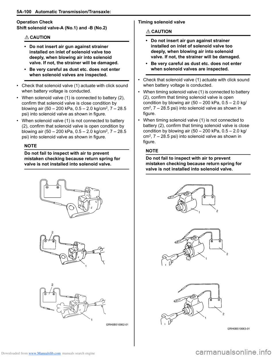
• Check that solenoid valve (1) actuate with click sound when battery voltage is conducted.
• When solenoid valve (1) is connected to battery (2), confirm that solenoid valve is close condition by
blowing air (50 – 200 kPa, 0.5 – 2.0 kg/cm
2, 7 – 28.5
psi) into solenoid valve as shown in figure.
• When solenoid valve (1) is not connected to battery (2), confirm that solenoid valve is open condition by
blowing air (50 – 200 kPa, 0.5 – 2.0 kg/cm
2, 7 – 28.5
psi) into solenoid valve as shown in figure.
NOTE
Do not fail to inspect with air to prevent
mistaken checking because return spring for
valve is not installe d into solenoid valve.
Timing solenoid valve
CAUTION!
• Do not insert air gun against strainer
installed on inlet of solenoid valve too
deeply, when blowing air into solenoid
valve. If not, the strainer will be damaged.
• Be very careful as dust etc. does not enter when solenoid valves are inspected.
• Check that solenoid valve (1) actuate with click sound
when battery voltage is conducted.
• When timing solenoid valve (1 ) is connected to battery
(2), confirm that timing solenoid valve is open
condition by blowing air (50 – 200 kPa, 0.5 – 2.0 kg/
cm
2, 7 – 28.5 psi) into solenoid valve as shown in
figure.
• When timing solenoid valve (1) is not connected to battery (2), confirm that timi ng solenoid valve is close
condition by blowing air (50 – 200 kPa, 0.5 – 2.0 kg/
cm
2, 7 – 28.5 psi) into solenoid valve as shown in
figure.
NOTE
Do not fail to inspect with air to prevent
mistaken checking because return spring for
valve is not installed into solenoid valve.
I2RH0B510062-01I2RH0B510063-01
Page 745 of 1496
Downloaded from www.Manualslib.com manuals search engine Automatic Transmission/Transaxle: 5A-101
Pressure Control Solenoid Valves (Pressure
Control Solenoid and TCC Pressure Control
Solenoid) Removal and Installation
S7RS0B5106024
Removal1) Disconnect negative cable at battery.
2) Lift up vehicle.
3) Remove drain plug and drain A/T fluid.
4) Install drain plug.
Tightening torque
A/T fluid drain plug: 17 N·m (1.7 kgf-m, 12.5 lb-ft)
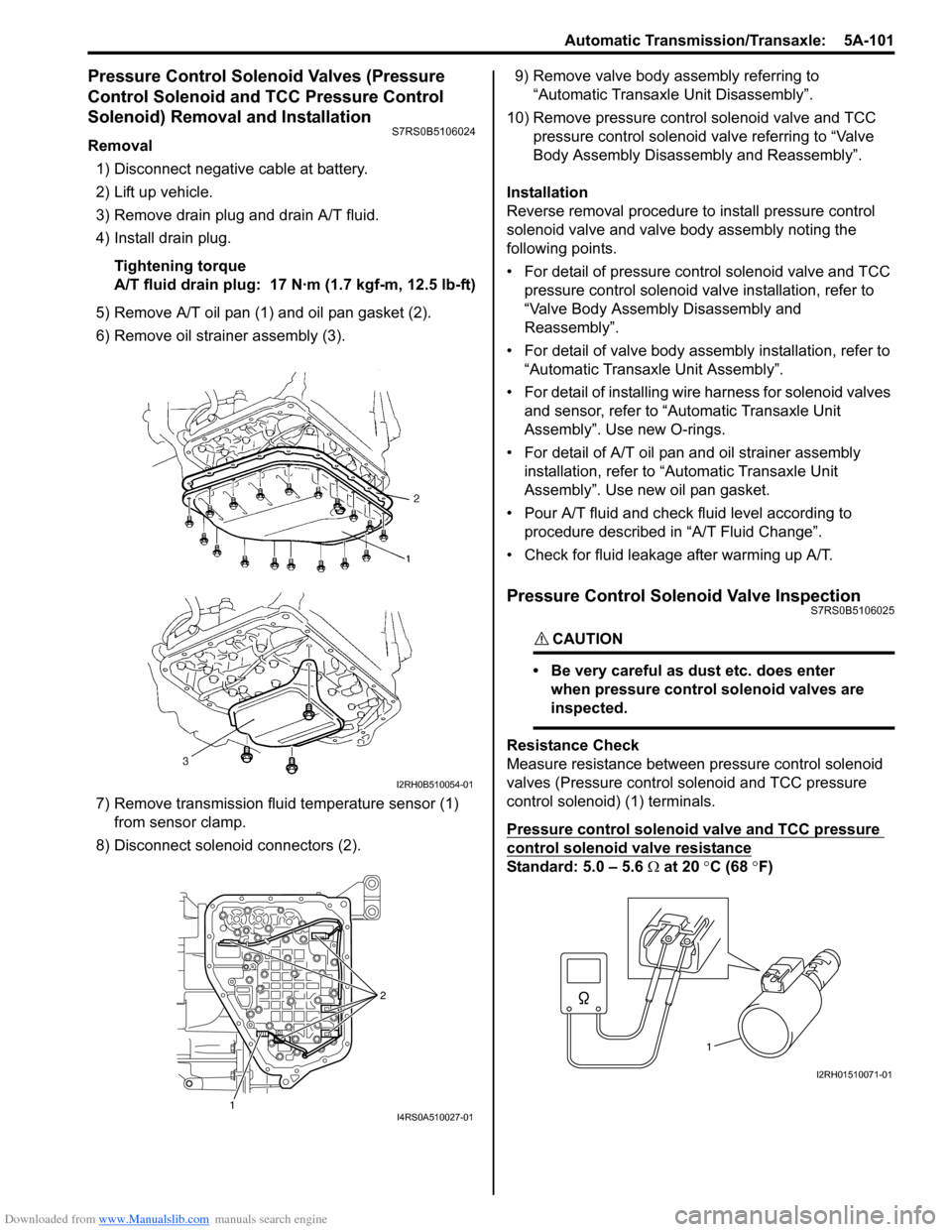
5) Remove A/T oil pan (1) and oil pan gasket (2).
6) Remove oil strain er assembly (3).
7) Remove transmission fluid temperature sensor (1) from sensor clamp.
8) Disconnect solenoid connectors (2). 9) Remove valve body assembly referring to
“Automatic Transaxl e Unit Disassembly”.
10) Remove pressure control solenoid valve and TCC pressure control solenoid valve referring to “Valve
Body Assembly Disassembly and Reassembly”.
Installation
Reverse removal procedure to install pressure control
solenoid valve and valve body assembly noting the
following points.
• For detail of pressure control solenoid valve and TCC pressure control solenoid va lve installation, refer to
“Valve Body Assembly Disassembly and
Reassembly”.
• For detail of valve body asse mbly installation, refer to
“Automatic Transaxle Unit Assembly”.
• For detail of installing wire harness for solenoid valves and sensor, refer to “Automatic Transaxle Unit
Assembly”. Use new O-rings.
• For detail of A/T oil pan and oil strainer assembly
installation, refer to “A utomatic Transaxle Unit
Assembly”. Use new oil pan gasket.
• Pour A/T fluid and check fluid level according to procedure described in “A/T Fluid Change”.
• Check for fluid leakage after warming up A/T.
Pressure Control Solenoid Valve InspectionS7RS0B5106025
CAUTION!
• Be very careful as dust etc. does enter when pressure control solenoid valves are
inspected.
Resistance Check
Measure resistance between pressure control solenoid
valves (Pressure control solenoid and TCC pressure
control solenoid) (1) terminals.
Pressure control solenoid valve and TCC pressure
control solenoid valve resistance
Standard: 5.0 – 5.6 Ω at 20 °C (68 °F)
I2RH0B510054-01
1 2I4RS0A510027-01
1
I2RH01510071-01