2008 SUZUKI SWIFT Enter
[x] Cancel search: EnterPage 1466 of 1496
Downloaded from www.Manualslib.com manuals search engine 10E-4 Keyless Start System:
Door Lock Function of Keyless Start SystemS7RS0BA501004
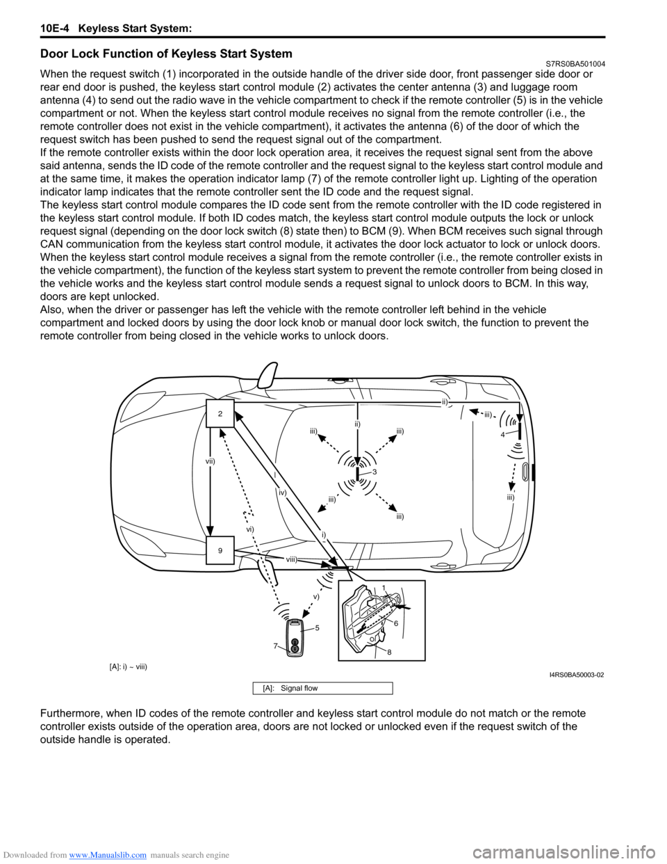
When the request switch (1) incorporated in the outside handle of the driver side door, front passenger side door or
rear end door is pushed, the keyless start control modul e (2) activates the center antenna (3) and luggage room
antenna (4) to send out the radio wave in the vehicle compartm ent to check if the remote controller (5) is in the vehicle
compartment or not. When the keyless start control module receives no signal from the remote controller (i.e., the
remote controller does not exist in the vehicle compartment) , it activates the antenna (6) of the door of which the
request switch has been pushed to send the request signal out of the compartment.
If the remote controller exists within the door lock operati on area, it receives the request signal sent from the above
said antenna, sends the ID code of the remote controller and the request signal to the keyless start control module and
at the same time, it makes the operatio n indicator lamp (7) of the remote controller light up. Lighting of the operation
indicator lamp indicates that the remote controller sent the ID code and the request signal.
The keyless start control module compares the ID code sent from the remote controller with the ID code registered in
the keyless start control module. If both ID codes match, the keyless start control module outputs the lock or unlock
request signal (depending on the door lock switch (8) stat e then) to BCM (9). When BCM receives such signal through
CAN communication from the keyless start control module, it activates the door lock actuator to lock or unlock doors.
When the keyless start control module receiv es a signal from the remote controller (i.e., the remote controller exists in
the vehicle compartment), the function of the keyless start system to prevent the remote controller from being closed in
the vehicle works and the keyless start control module sends a request signal to unlock doors to BCM. In this way,
doors are kept unlocked.
Also, when the driver or passenger has left the vehicl e with the remote controller left behind in the vehicle
compartment and locked doors by using the door lock knob or manual door lock switch, the function to prevent the
remote controller from being closed in the vehicle works to unlock doors.
Furthermore, when ID codes of the remote controller and keyless start control module do not match or the remote
controller exists outside of the operation area, doors are not locked or unlocked even if the request switch of the
outside handle is operated.
9 2
vi)
v)
vii) iv)
i) ii)
iii)
iii)iii)
ii)
iii)
iii)
iii)
3
5
8
6
1 4
7
[A]: i) ~ viii)
viii)
I4RS0BA50003-02
[A]: Signal flow
Page 1467 of 1496
Downloaded from www.Manualslib.com manuals search engine Keyless Start System: 10E-5
Operation Area of Remote ControllerS7RS0BA501005
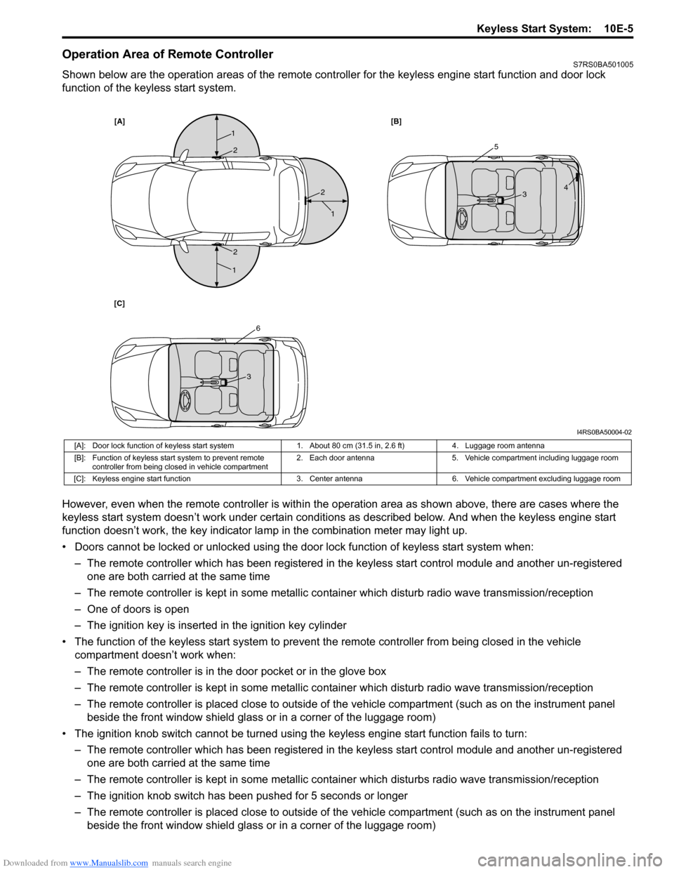
Shown below are the operation areas of the remote controller for the keyless engine start function and door lock
function of the keyless start system.
However, even when the remote controller is within the operation area as shown above, there are cases where the
keyless start system doesn’t work under certain conditi ons as described below. And when the keyless engine start
function doesn’t work, the key indicator la mp in the combination meter may light up.
• Doors cannot be locked or unlocked using the doo r lock function of keyless start system when:
– The remote controller which has been registered in the keyless start control module and another un-registered one are both carried at the same time
– The remote controller is kept in some metallic co ntainer which disturb radio wave transmission/reception
– One of doors is open
– The ignition key is inserted in the ignition key cylinder
• The function of the keyless start system to prevent the remote controller from being closed in the vehicle
compartment doesn’t work when:
– The remote controller is in the door pocket or in the glove box
– The remote controller is kept in some metallic co ntainer which disturb radio wave transmission/reception
– The remote controller is placed close to outside of the vehicle compartment (such as on the instrument panel beside the front window shield glass or in a corner of the luggage room)
• The ignition knob switch cannot be turned usin g the keyless engine start function fails to turn:
– The remote controller which has been registered in the keyless start control module and another un-registered one are both carried at the same time
– The remote controller is kept in some metallic cont ainer which disturbs radio wave transmission/reception
– The ignition knob switch has been pushed for 5 seconds or longer
– The remote controller is placed close to outside of the vehicle compartment (such as on the instrument panel beside the front window shield glass or in a corner of the luggage room)
[A] [B]
[C]
1
1
1
25
6
3
3 4
2
2
I4RS0BA50004-02
[A]: Door lock function of keyless start system 1. About 80 cm (31.5 in, 2.6 ft)4. Luggage room antenna
[B]: Function of keyless start system to prevent remote controller from being closed in vehicle compartment 2. Each door antenna
5. Vehicle compartment including luggage room
[C]: Keyless engine start function 3. Center antenna6. Vehicle compartment excluding luggage room
Page 1469 of 1496
Downloaded from www.Manualslib.com manuals search engine Keyless Start System: 10E-7
Schematic and Routing Diagram
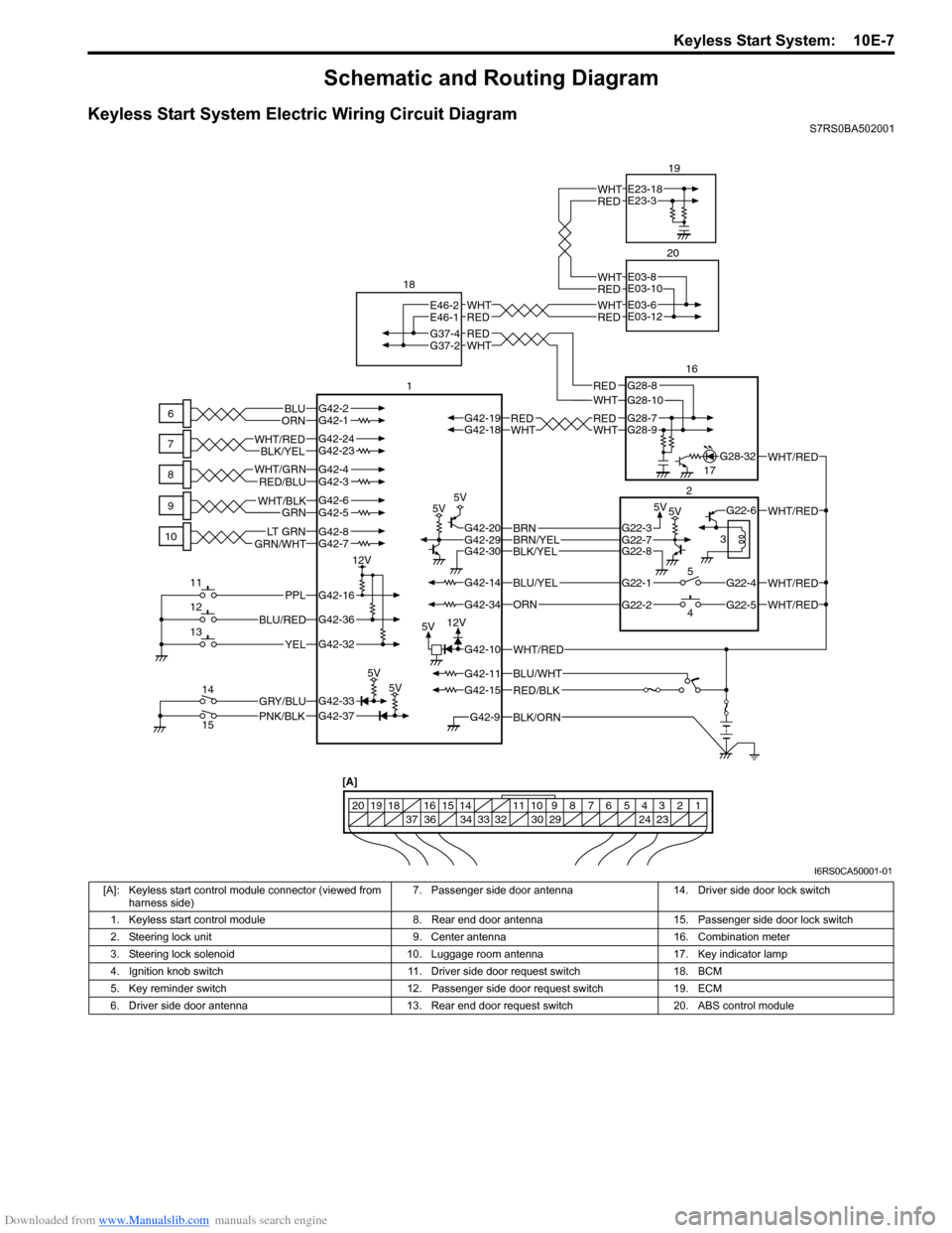
Keyless Start System Electric Wiring Circuit DiagramS7RS0BA502001
BLK/ORNG42-9
G42-15
G42-14
G42-37G42-33
G42-16
G42-20G42-29G42-30
G42-36
G42-32G42-10
G42-34
G42-11BLU/WHT
WHT/RED
WHT/RED
WHT/RED
PNK/BLKGRY/BLU
BLU/RED
YEL
PPL
RED/BLK
5V5V
5V5V
5V5V
5V
12V
12V
G42-2G42-1BLUORNWHTREDWHTREDG42-18G42-19G28-9G28-7
BLU/YEL
ORN
G42-24G42-23BLK/YELWHT/RED
G42-7GRN/WHTLT G R NG42-8
G42-5G42-6GRNWHT/BLK
G42-4G42-3WHT/GRNRED/BLU
BLK/YELBRN/YELBRNG22-3
G22-1
G22-2G22-5
G22-4
G22-6
G22-7G22-8
WHT/RED
WHT/RED
G37-4
REDWHTREDWHT
G28-10G28-8WHTRED
RED
WHT
G37-2
E46-2
E46-1E03-6
E03-12
G28-32
6
7
8
9
10
11
12
13
14
15 1
18
20
1617
2
4 5 3
1234567891011
141516
36 34 33 32 30 29 24 23
37
181920
[A]
REDWHTE23-18
E23-3
19
REDWHTE03-8
E03-10
I6RS0CA50001-01
[A]: Keyless start control module connector (viewed from
harness side) 7. Passenger side door antenna 14. Driver side door lock switch
1. Keyless start control module 8. Rear end door antenna 15. Passenger side door lock switch
2. Steering lock unit 9. Center antenna 16. Combination meter
3. Steering lock solenoid 10. Luggage room antenna 17. Key indicator lamp
4. Ignition knob switch 11. Driver side door request switch 18. BCM
5. Key reminder switch 12. Passenger side door request switch 19. ECM
6. Driver side door antenna 13. Rear end door request switch 20. ABS control module
Page 1477 of 1496
Downloaded from www.Manualslib.com manuals search engine Keyless Start System: 10E-15
Terminal Number Circuit Normal
Vo l ta g e Condition
G42-1 Driver side door antenna (–) *0 – 5 V Refer to “Reference waveform No. 1: ”
G42-2 Driver side door antenna (+)
G42-3 Rear end door antenna (–) *0 – 5 V Refer to “Reference waveform No. 1: ”
G42-4 Rear end door antenna (+)
G42-5 Center antenna (–) *–2 – 2 V Refer to “Reference waveform No. 2: ”
G42-6 Center antenna (+) *–10 – 15 V
G42-7 Luggage room antenna (–) *–10 – 10 V Refer to “Reference waveform No. 3: ”
G42-8 Luggage room antenna (+) *–8 – 14 V
G42-9 Ground for keyless start control module 0 – 1 V Ignition switch is at all positions
G42-10 Power source 10 – 12 V Ignition switch is at all positions
G42-11 Ignition switch (ACC signal) 10 – 12 V Ignition switch is at ACC or ON position
0 – 1 V Ignition switch is at any position other than
ACC or ON position
G42-12 — — —
G42-13 — — —
G42-14 Ignition switch (Key reminder signal) 10 – 12 V Insert ignition key to ignition key cylinder
0 – 1 V Pull out ignition key from ignition key
cylinder
G42-15 Ignition switch (ON signal) 10 – 12 V Ignition switch is at ON position
0 – 1 V Ignition switch is at any position other than
ON position
G42-16 Driver side door request switch 10 – 12 V
Request switch of driver side door is
released
0 – 1 V Request switch of driver side door is
pushed
G42-17 — — —
G42-18 CAN communication line (low) *1.6 – 2.5 V Refer to “Reference waveform No. 4: ”
G42-19 CAN communication line (high) *2.5 – 3.6 V
G42-20 Power supply for steering lock unit 4 – 6 V Full time
G42-21 — — —
G42-22 — — —
G42-23 Passenger side door antenna (–) *0 – 5 V Refer to “Reference waveform No. 1: ”
G42-24 Passenger side door antenna (+)
G42-25 — — —
G42-26 — — —
G42-27 — — —
G42-28 — — —
G42-29 Signal for steering lock unit 4 – 6 VIgnition knob switch is at any position other
than ON and OFF position
*0 – 5 V Refer to “Reference waveform No. 5: ”
G42-30 Ground for steering lock unit 0 – 1 V Full time
G42-31 — — —
G42-32 Rear end door request switch 10 – 12 V Request switch of rear end door is released
0 – 1 V Request switch of rear end door is pushed
G42-33 Driver side door lock switch 0 – 1 V
Driver side door is at unlock position and
passenger side door is at lock position
4 – 6 V Driver and passenger side door is at lock
position
*3 – 5 V Refer to “Reference waveform No. 6: ”
G42-34 Ignition knob switch 10 – 12 V
When pushing ignition knob switch of
steering lock unit
0 – 1 V When releasing ignition knob switch of
steering lock unit
G42-35 — — —
G42-36 Passenger side door request switch 10 – 12 V
Request switch of passenger side door is
released
0 – 1 V Request switch of passenger side door is
pushed
Page 1478 of 1496
Downloaded from www.Manualslib.com manuals search engine 10E-16 Keyless Start System:
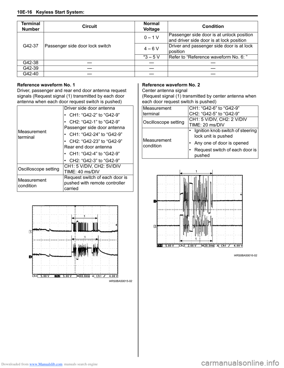
Reference waveform No. 1
Driver, passenger and rear end door antenna request
signals (Request signal (1) transmitted by each door
antenna when each door request switch is pushed)Reference waveform No. 2
Center antenna signal
(Request signal (1) transmitted by center antenna when
each door request switch is pushed)
G42-37 Passenger side door lock switch
0 – 1 V
Passenger side door is at unlock position
and driver side door is at lock position
4 – 6 V Driver and passenger side door is at lock
position
*3 – 5 V Refer to “Reference waveform No. 6: ”
G42-38 — — —
G42-39 — — —
G42-40 — — —
Terminal
Number Circuit Normal
Vo l ta g e Condition
Measurement
terminalDriver side door antenna
• CH1: “G42-2” to “G42-9”
• CH2: “G42-1” to “G42-9”
Passenger side door antenna
• CH1: “G42-24” to “G42-9”
• CH2: “G42-23” to “G42-9”
Rear end door antenna
• CH1: “G42-4” to “G42-9”
• CH2: “G42-3” to “G42-9”
Oscilloscope setting CH1: 5 V/DIV, CH2: 5V/DIV
TIME: 40 ms/DIV
Measurement
condition Request switch of each door is
pushed with remote controller
carried
I4RS0BA50015-02
Measurement
terminal
CH1: “G42-6” to “G42-9”
CH2: “G42-5” to “G42-9”
Oscilloscope setting CH1: 5 V/DIV, CH2: 2 V/DIV
TIME: 20 ms/DIV
Measurement
condition • Ignition knob switch of steering
lock unit is pushed
• Any one of door is opened
• Request switch of each door is pushed
I4RS0BA50016-02
Page 1492 of 1496
Downloaded from www.Manualslib.com manuals search engine 10E-30 Keyless Start System:
Repair Instructions
Antennas and Request Switches Removal and InstallationS7RS0BA506001
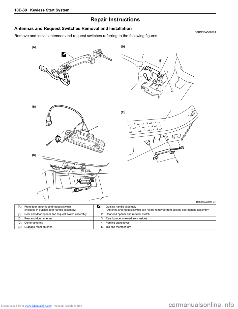
Remove and install antennas and request switches referring to the following figures.
[A]
[B][D]
[C] [E]
1
2
3
4
5
I4RS0BA50027-04
[A]: Front door antenna and request switch
(included in outside door handle assembly) 1. Outside handle assembly
: Antenna and request switch can not be removed from outside door handle assembly
[B]: Rear end door opener and request switch assembly 2. Rear end opener and request switch
[C]: Rear end door antenna 3. Rear bumper (viewed from inside)
[D]: Center antenna 4. Parking brake lever [E]: Luggage room antenna 5. Tail end member trim
Page 1496 of 1496
Downloaded from www.Manualslib.com manuals search engine 10E-34 Keyless Start System:
If remote controller or keyless start control module is
replaced with a new one or additional remote controller
is necessary, register ID code(s) of remote controller.1) Sit in driver seat and close all doors.
2) Check that door lock of driver seat is unlocked.
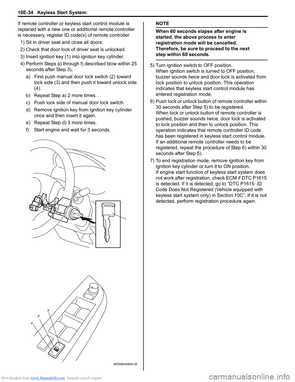
3) Insert ignition key (1) in to ignition key cylinder.
4) Perform Steps a) through f) described blow within 25 seconds after Step 3).
a) First push manual door lock switch (2) toward
lock side (3) and then push it toward unlock side
(4).
b) Repeat Step a) 2 more times.
c) Push lock side of manual door lock switch.
d) Remove ignition key from ignition key cylinder once and then insert it again.
e) Repeat Step d) 3 more times.
f) Start engine and wait for 3 seconds.NOTE
When 60 seconds elapse after engine is
started, the above process to enter
registration mode will be cancelled.
Therefore, be sure to proceed to the next
step within 60 seconds.
5) Turn ignition switch to OFF position. When ignition switch is turned to OFF position,
buzzer sounds twice and door lock is activated from
lock position to unlock po sition. This operation
indicates that keyless st art control module has
entered registration mode.
6) Push lock or unlock button of remote controller within 30 seconds after Step 5) to be registered.
When lock or unlock button of remote controller is
pushed, buzzer sounds twice, door lock is activated
to lock position and then to unlock position. This
operation indicates that remote controller ID code
has been registered in keyless start control module.
If an additional remote controller needs to be
registered, repeat the procedure of Step 6) within 30
seconds after Step 5).
7) To end registration mode, remove ignition key from ignition key cylinder or turn it to ON position.
If engine start function of keyless start system does
not work after registration , check ECM if DTC P1615
is detected. If it is detected, go to “DTC P1615: ID
Code Does Not Registered (Vehicle equipped with
keyless start system only) in Section 10C”. If it is not
detected, perform registration procedure again.
1
2
4 3
I4RS0BA50034-02