2008 SUZUKI SWIFT Tran
[x] Cancel search: TranPage 400 of 1496

Downloaded from www.Manualslib.com manuals search engine 1H-8 Ignition System:
Ignition Coil Assembly (Including ignitor)
Removal and Installation
S7RS0B1806005
Removal1) Disconnect negative (–) cable at battery.
2) Remove air cleaner assembly with air intake pipe and cylinder head upper cover.
3) Disconnect ignition coil coupler.
4) Disconnect high-tension cord (3) from ignition coil assembly (2).
5) Remove ignition coil bolts (1) and then pull out ignition coil assembly.
Installation 1) Install ignition coil assembly (2).
2) Tighten ignition coil bolts (1) to specified torque, and then connect igni tion coil coupler.
Tightening torque
Ignition coil bolt (a): 10 N·m (1.0 kgf-m, 7.5 lb-ft)
3) Install high-tension cord (3) to ignition coil assembly while gripping its cap.
4) Install cylinder head upper cover and air cleaner assembly with air intake pipe.
5) Connect negative (–) cable to battery.
Ignition Coil Assembly (Including ignitor)
Inspection
S7RS0B1806006
Measure secondary coil for resistance.
If resistance is out of specification, replace ignition coil
assembly.
Secondary coil resistance
7.5 – 10.3 k Ω at 20 °C, 68 ° F
Ignition Timing InspectionS7RS0B1806007
NOTE
• Ignition timing is not adjustable. If ignition
timing is out of specification, check
system related parts.
• Before starting engine, place transmission gear shift lever in “Neutral” (shift selector
lever to “P” range for A/T model), and set
parking brake.
1) Connect scan tool to DLC (1) with ignition switch OFF.
Special tool
(A): SUZUKI scan tool
2) Start engine and warm it up to normal operating temperature.
3) Make sure that all of electrical loads except ignition are switched off.
4) Check to be sure that idle speed is within specification referring to “Idle Speed and IAC
Throttle Valve Opening Inspection in Section 1A”
5) Fix ignition timing by using “Fixed Spark” of “Misc Test” mode on scan tool.
I2RH0B180006-01
I3RM0A180004-01
I2RH0B180007-01
(A)
1
I4RS0B180003-01
Page 402 of 1496
Downloaded from www.Manualslib.com manuals search engine 1I-1 Starting System:
Engine
Starting System
Schematic and Routing Diagram
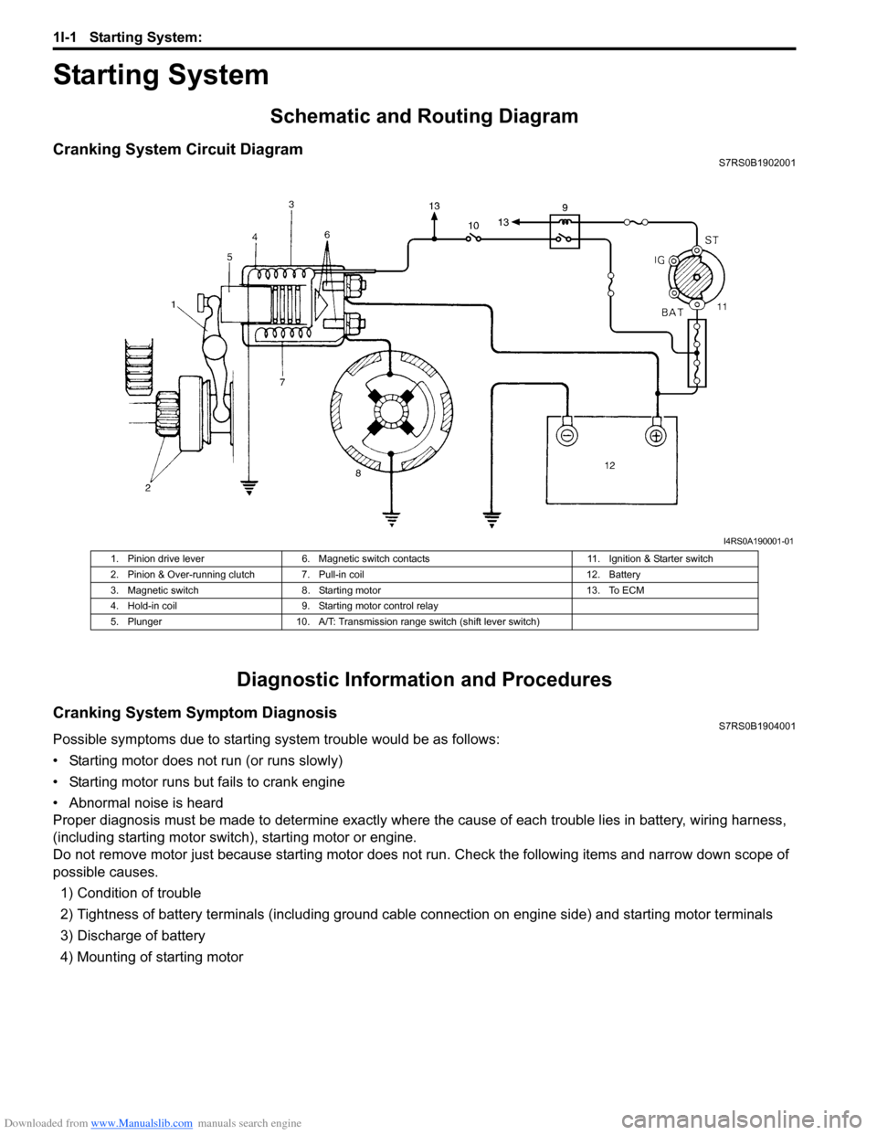
Cranking System Circuit DiagramS7RS0B1902001
Diagnostic Information and Procedures
Cranking System Symptom DiagnosisS7RS0B1904001
Possible symptoms due to starting system trouble would be as follows:
• Starting motor does not run (or runs slowly)
• Starting motor runs but fails to crank engine
• Abnormal noise is heard
Proper diagnosis must be made to determine exactly where the cause of each trouble lies in battery, wiring harness,
(including starting motor switch), starting motor or engine.
Do not remove motor just because starting motor does not run. Check the following items and narrow down scope of
possible causes.
1) Condition of trouble
2) Tightness of battery terminals (including ground cable connection on engine side) and starting motor terminals
3) Discharge of battery
4) Mounting of starting motor
I4RS0A190001-01
1. Pinion drive lever 6. Magnetic switch contacts 11. Ignition & Starter switch
2. Pinion & Over-running clutch 7. Pull-in coil 12. Battery
3. Magnetic switch 8. Starting motor 13. To ECM
4. Hold-in coil 9. Starting motor control relay
5. Plunger 10. A/T: Transmission range switch (shift lever switch)
Page 405 of 1496

Downloaded from www.Manualslib.com manuals search engine Starting System: 1I-4
Repair Instructions
Starting Motor Dismounting and RemountingS7RS0B1906001
Dismounting1) Disconnect negative (–) battery lead at battery.
2) Disconnect magnetic switch lead wire (1) and battery cable (2) from starting motor terminals.
3) Detach shift & select control cable bracket from transaxle. (M/T model only)
4) Remove starting motor mount bolt (3) and nut (4).
5) Remove starting motor (5).
Remounting
Reverse the dismounting procedure noting the following.
• Tighten battery cable nut (6) to specified torque.
Tightening torque
Starting motor battery cable nut (a): 9.8 N·m (0.98 kgf-m, 7.0 lb-ft)
I4RS0A190002-01
: 9.8 N ⋅m (0.98 kgf-m, 7.0 lb-ft)
Page 416 of 1496
Downloaded from www.Manualslib.com manuals search engine 1J-6 Charging System:
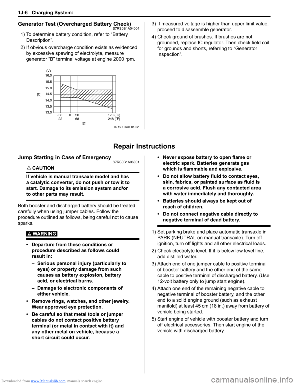
Generator Test (Overcharged Battery Check)S7RS0B1A04004
1) To determine battery condition, refer to “Battery Description”.
2) If obvious overcharge condition exists as evidenced by excessive spewing of electrolyte, measure
generator “B” terminal voltage at engine 2000 rpm. 3) If measured voltage is higher than upper limit value,
proceed to disassemble generator.
4) Check ground of brushes. If brushes are not grounded, replace IC regulator. Then check field coil
for grounds and shorts, referring to “Generator
Inspection”.
Repair Instructions
Jump Starting in Case of EmergencyS7RS0B1A06001
CAUTION!
If vehicle is manual transaxle model and has
a catalytic converter, do not push or tow it to
start. Damage to its emission system and/or
to other parts may result.
Both booster and discharged battery should be treated
carefully when using ju mper cables. Follow the
procedure outlined as follows, being careful not to cause
sparks.
WARNING!
• Departure from these conditions or procedure described as follows could
result in:
– Serious personal injury (particularly to eyes) or property damage from such
causes as battery explosion, battery
acid, or electrical burns.
– Damage to electronic components of either vehicle.
• Remove rings, watches, and other jewelry. Wear approved eye protection.
• Be careful so that metal tools or jumper cables do not contact positive battery
terminal (or metal in contact with it) and
any other metal on vehicle, because a
short circuit could occur. • Never expose battery to open flame or
electric spark. Batteries generate gas
which is flammable and explosive.
• Do not allow battery fluid to contact eyes, skin, fabrics, or painted surface as fluid is
a corrosive acid. Flush any contacted area
with water immediately and thoroughly.
• Batteries should always be kept out of reach of children.
• Do not connect negative cable directly to negative terminal of dead battery.
1) Set parking brake and place automatic transaxle in PARK (NEUTRAL on manual transaxle). Turn off
ignition, turn off lights and all other electrical loads.
2) Check electrolyte level. If it is below low level line, add distilled water.
3) Attach end of one jumper cable to positive terminal of booster battery and the other end of the same
cable to positive terminal of discharged battery. (Use
12-volt battery only to jump start engine).
4) Attach one end of the remaining negative cable to negative terminal of booster battery, and the other
end to a solid engine ground (such as exhaust
manifold) at least 45 cm (18 in.) away from battery of
vehicle being started.
5) Start engine of vehicle with booster battery and turn off electrical accessories. Then start engine of the
vehicle with discharged battery.
16.0
15.5
15.0
14.5
14.0
13.5
13.0 -30 0 20
[C]
[D]
68
22120 (˚C)
248 (˚F)
(V)
I6RS0C1A0001-02
Page 479 of 1496

Downloaded from www.Manualslib.com manuals search engine Drive Shaft / Axle: 3A-1
Driveline / Axle
Drive Shaft / Axle
General Description
Front Drive Shaft ConstructionS7RS0B3101001
A constant velocity ball joint is used on the wheel side of both right and left side drive shaft assemblies. For A/T
vehicle, a tripod type constant velocity joint is used on the differential side and center shaft side. For M/T vehicle, a
double offset type constant velocity joint (DOJ) is used on the differential side and center shaft side. The drive shaft
can slide through the tripod joint or the double offset joint (DOJ) in the extension/contraction direction.
Component Location
Front Drive Shaft Assembly Components LocationS7RS0B3103001
I6RS0C310002-03
1. To transaxle 8. Ball stud washer : 45 N⋅m (4.5 kgf-m, 32.5 lb-ft)
2. Drive shaft assembly 9. Tie-rod end nut : 60 N⋅m (6.0 kgf-m, 43.5 lb-ft)
3. Tie-rod end 10. Ball stud bolt : 200 N⋅m (20.0 kgf-m, 145.0 lb-ft)
4. Center bearing support 11. Drive shaft nut
: After tightening nut, caulk nut securely. : 85 N
⋅m (8.5 kgf-m, 61.5 lb-ft)
5. Center shaft 12. Wheel nut : Do not reuse.
6. Center bearing support bolts 13. Drive shaft washer
7. Ball stud nut : 55 N⋅m (5.5 kgf-m, 40.0 lb-ft)
Page 482 of 1496
Downloaded from www.Manualslib.com manuals search engine 3A-4 Drive Shaft / Axle:
Front Drive Shaft Assembly On-Vehicle
Inspection
S7RS0B3106002
• Check boots for breakage or deterioration.
• Check wheel side joint for rattle or smooth rotation.
• Check differential side (or center shaft side) joint for smooth rotation.
If any abnormality is found, replace.
Front Drive Shaft Assembly Removal and
Installation
S7RS0B3106003
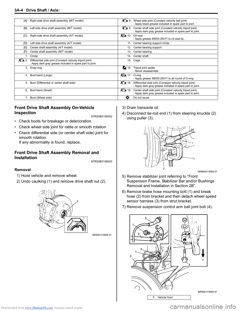
Removal
1) Hoist vehicle and remove wheel.
2) Undo caulking (1) and remove drive shaft nut (2). 3) Drain transaxle oil.
4) Disconnect tie-rod end (1) from steering knuckle (2)
using puller (3).
5) Remove stabilizer join t referring to “Front
Suspension Frame, Stabiliz er Bar and/or Bushings
Removal and Installati on in Section 2B”.
6) Remove brake hose mounting bolt (1) and break hose (2) from bracket and then detach wheel speed
sensor harness (3) from strut bracket.
7) Remove suspension contro l arm ball joint bolt (4).
[A]: Right side drive shaft assembly (M/T model) 8. Wheel side joint (Constant velocity ball joint)
: Apply black grease included in spare part to joint.
[B]: Left side drive shaft assembly (M/T model) 9. Center shaft side joint (Constant velocity tripod joint)
: Apply dark gray grease included in spare part to joint.
[C]: Right side drive shaft assembly (A/T model) 10. Oil seal
: Apply grease 99000-25011 to oil seal lip.
[D]: Left side drive shaft assembly (A/T model) 11. Center bearing support circlip
[E]: Center shaft assembly (A/T model) 12. Center bearing support
[F]: Center shaft assembly (M/T model) 13. Center bearing
1. Circlip 14. Center shaft
2. Differential side joint (Constant velocity tripod joint) : Apply dark gray grease included in spare part to joint. 15. Cage
3. Snap ring 16. Tripod joint spider
: Never disassemble.
4. Boot band (Large) 17. O-ring
: Apply grease 99000-25011 to all round of O-ring.
5. Boot (Differential or center shaft side) 18. Differential side joint (Constant velocity tripod joint)
: Apply dark gray grease included in spare part to joint.
6. Boot band (Small) 19. Center shaft side joint (Constant velocity tripod joint)
: Apply dark gray grease included is spare part to joint.
7. Boot (Wheel side) : Do not reuse.
I6RS0C310004-01
F: Vehicle front
I3RM0A310003-01
I6RS0C310005-01
Page 483 of 1496
Downloaded from www.Manualslib.com manuals search engine Drive Shaft / Axle: 3A-5
8) Disconnect front suspension control arm ball joint
stud from steering knuckle.
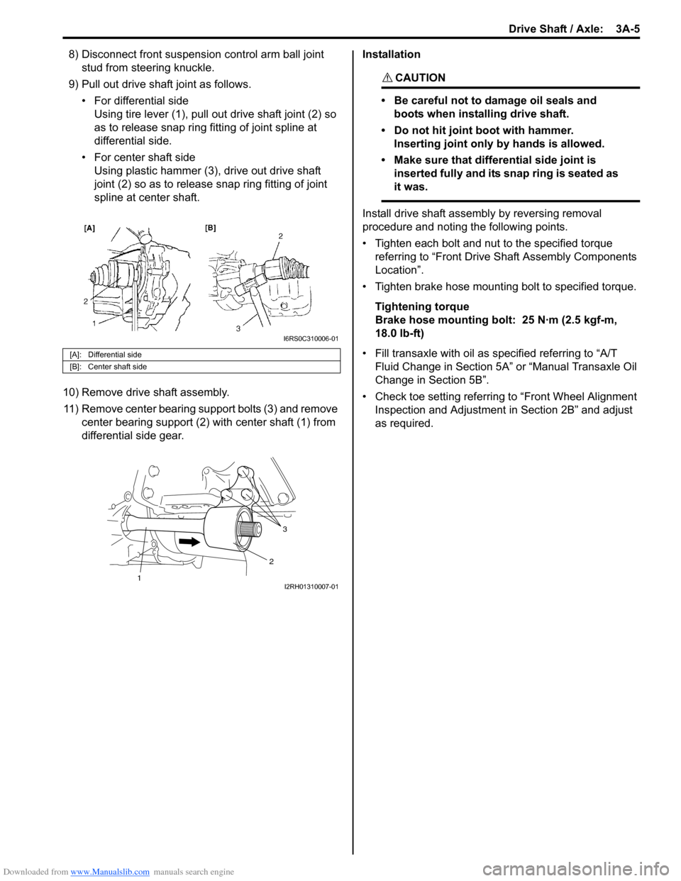
9) Pull out drive shaft joint as follows. • For differential sideUsing tire lever (1), pull out drive shaft joint (2) so
as to release snap ring fitting of joint spline at
differential side.
• For center shaft side Using plastic hammer (3), drive out drive shaft
joint (2) so as to release snap ring fitting of joint
spline at center shaft.
10) Remove drive shaft assembly. 11) Remove center bearing support bolts (3) and remove center bearing support (2) with center shaft (1) from
differential side gear. Installation
CAUTION!
• Be careful not to damage oil seals and
boots when installing drive shaft.
• Do not hit joint boot with hammer. Inserting joint only by hands is allowed.
• Make sure that differential side joint is inserted fully and its snap ring is seated as
it was.
Install drive shaft assemb ly by reversing removal
procedure and noting the following points.
• Tighten each bolt and nut to the specified torque referring to “Front Drive Shaft Assembly Components
Location”.
• Tighten brake hose mounting bolt to specified torque.
Tightening torque
Brake hose mounting bolt: 25 N·m (2.5 kgf-m,
18.0 lb-ft)
• Fill transaxle with oil as sp ecified referring to “A/T
Fluid Change in Section 5A” or “Manual Transaxle Oil
Change in Section 5B”.
• Check toe setting referring to “Front Wheel Alignment Inspection and Adjustment in Section 2B” and adjust
as required.
[A]: Differential side
[B]: Center shaft side
I6RS0C310006-01
3
2
1I2RH01310007-01
Page 541 of 1496
Downloaded from www.Manualslib.com manuals search engine ABS: 4E-2
General Description
ABS DescriptionS7RS0B4501001
The ABS (Antilock Brake System) controls the fluid
pressure applied to the wheel cylinder of each brake
from the master cylinder so that each wheel is not locked
even when hard braking is applied.
This ABS has also the following function.
While braking is applied, but before ABS control
becomes effective, braking force is distributed between
the front and rear so as to prevent the rear wheels from
being locked too early for better stability of the vehicle.
The main component parts of this ABS include the
following parts in addition to those of the conventional
brake system.
• Wheel speed sensor which senses revolution speed of each wheel and outputs its signal.
• ABS warning light which light s to inform abnormality
when system fails to operate properly.
• ABS hydraulic unit / cont rol module assembly is
incorporated ABS co ntrol module, ABS hydraulic unit
(actuator assembly), solenoid valve power supply
driver (transistor), solenoid valve driver (transistor),
pump motor driver (transistor).
– ABS control module which sends operation signal to ABS hydraulic unit to control fluid pressure
applied to each wheel cylinder based on signal
from each wheel speed sensor so as to prevent
wheel from locking.
– ABS hydraulic unit which operates according to signal from ABS control module to control fluid
pressure applied to wheel cylinder of each 4
wheels.
– Solenoid valve power supp ly driver (transistor)
which supplies power to solenoid valve in ABS
hydraulic unit.
– Solenoid valve driver (transistor) which controls each solenoid valves in ABS hydraulic unit.
– Pump motor driver (transistor) which supplies power to pump motor in ABS hydraulic unit.
This ABS is equipped with Electronic Brake force
Distribution (EBD) system that controls a fluid pressure
of rear wheels to best condition, which is the same
function as that of proportion ing valve, by the signal from
wheel sensor independently of change of load due to
load capacity and so on. An d if the EBD system fails to
operate properly, the brake warning light lights to inform
abnormality.
ABS Hydraulic Unit / Control Module Assembly
Description
S7RS0B4501002
ABS control module is a component of ABS hydraulic
unit / control module asse mbly and has the following
functions.
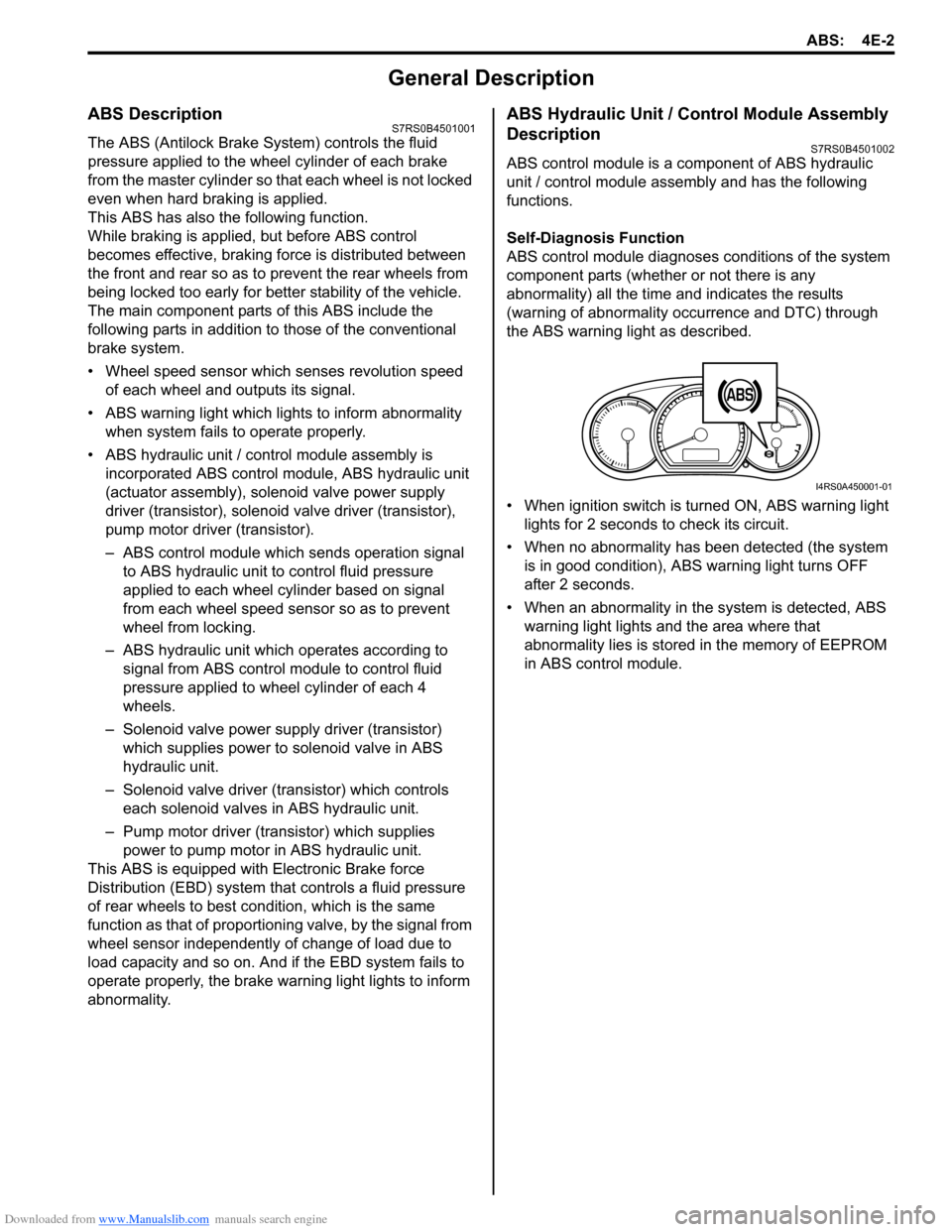
Self-Diagnosis Function
ABS control module diagnose s conditions of the system
component parts (whether or not there is any
abnormality) all the time and indicates the results
(warning of abnormality occurrence and DTC) through
the ABS warning light as described.
• When ignition switch is turned ON, ABS warning light lights for 2 seconds to check its circuit.
• When no abnormality has been detected (the system is in good condition), ABS warning light turns OFF
after 2 seconds.
• When an abnormality in th e system is detected, ABS
warning light lights and the area where that
abnormality lies is stored in the memory of EEPROM
in ABS control module.
1
I4RS0A450001-01