Page 1262 of 1496
Downloaded from www.Manualslib.com manuals search engine 9A-91 Wiring Systems:
E-2 Auto A/C System Circuit DiagramS7RS0B910E033
12G53
G51
G52
G51
G52 G52 G51
251211
11
15
17
12V
198
REDGRN
RED/BLK
GRN/RED
RED/YEL
RED/YELRED/BLK
RED/BLKBLU/WHT
M
7133G01
8G34
ILL
Auto A/C panel
Sunload sensor
DLC Auto
unit
Air intake control actuator
BACK
10A24
"A-5"
PW
"A-5"BW"D-4"RY
18
GRN/WHT
"A-8"GW
ECMBCMBCM
BLK/ORN
YEL/BLKPNK
5
PPL/WHT
PPL/WHT
BLK/ORNBLK/YEL
5V 5V
12V
J/B
7
YEL
YEL
"A-8"Y
109
G31
J/C
D
D
G15
J/C
B
B
BLK
BLK
G31
J/C
C
C
G16
J/C
C
C
G15
J/C
A A
11
BLK
A
G16
J/C
A
A
J/C
BG31B B
16
5
I7RS0B910932-01
Page 1263 of 1496
Downloaded from www.Manualslib.com manuals search engine Wiring Systems: 9A-92
G091
2
346
1698G52 G51
G52 G52
G51 G51G52
1
3
7
G495
6
M
G48
M
2
31141413
341
M
2G46
5G33
WHT/RED
WHT/RED
BLK/WHT
GRY/REDGRY/BLUWHTWHT/BLUBRN/WHTBRN/YELWHT/BLKGRN
WHTYELWHTWHT/BLU
GRNGRNBLKGRNGRN
BLK/YELBLK/YEL
BLK/WHTGRYBLK/WHTBLU/RED
Blower motor controller
A/C
DiodeAutounit
Blower
motor
15A RADIO
Evaporator
temperature
sensor Air flow control
actuator
Temperature
control actuator
40
635
71 2
G47
G051
2 1
5V5V
5V5V 12V
12V
12V
J/B
J/B
G326
1 2
5
3
30A HTR
FAN
4
10A
38IG2
SIG
Blowermotorrelay
E39
7
G349
G15
J/C
912
A
A
BLK
11
A
BLKBLK
BLU
J/C
B BG16
B
G16
J/C
DDDD
G17
J/C
B
B
Individual circuit fuse box (No.1)
G502
1
PNK/BLK
Inside air
temperature
sensor
5V
I7RS0B910946-02
Page 1265 of 1496
Downloaded from www.Manualslib.com manuals search engine Wiring Systems: 9A-94
L30
L25
L18 L411212
A/B
SDM
L29
L11L351
2
1
2
1235
1113
1420 192122
46
47
45
44
IF EQPD
Side-sensor Side-sensor
LT GRN/BLK
YEL/GRNBLK/YELBRN/YEL
Side curtain
Diagnosis
connector #3
Side air-bag Side air-bag Side curtain
L044
G3413
J/B
"C-3"
YB
2
YEL/BLK
YEL/BLK
WHT/REDWHT/GRNLT GRN
GRY/RED
PPL
GRY
12
BRN/WHTBRNYEL/BLU
12
1
L532
I7RS0B910947-01
Page 1273 of 1496
Downloaded from www.Manualslib.com manuals search engine Wiring Systems: 9A-102
G-2 Multi Information Display / Accessory Socket System Circuit DiagramS7RS0B910E038
11
BLU/WHT
BLU/WHT
15AACC 2
27
J/C
G17
L28
L44
YG
Multi information display
J/B
BCM
J/B
G34
7
14
RED/YEL
10
BLK/ORN
2
BLK/ORN
15A RADIO
40
G335
WHT/RED
G141
3
J/C
YEL
YEL
G16
4
57
G15
J/C
12L05
WHT/BLK
L46
ACC
Socket
2
1
18
WHT/BLK
BLK
BLK
3 1
C
C
B
B
C
C
GRY
G378
11
"D-4"
RY
YEL/RED
YEL/BLK
2E14
1
8
10E46
A
J/B side connector (BCM)
A
Outside air
temperature sensor
I7RS0B910948-01
Page 1278 of 1496

Downloaded from www.Manualslib.com manuals search engine 9A-107 Wiring Systems:
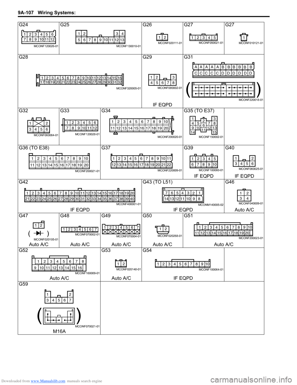
G24G25 G26G27 G27
G28 G29G31
IF EQPD
G32 G33G34 G35 (TO E37)
G36 (TO E38) G37G39G40
IF EQPD IF EQPD
G42 G43 (TO L51)G46
IF EQPD IF EQPDAuto A/C
G47 G48G49G50G51
Auto A/C Auto A/C Auto A/C Auto A/C Auto A/C
G52 G53G54
Auto A/C Auto A/CIF EQPD
G59
M16A
21
83
9 4
10 5
11 6
12
7
MCONF120026-01
710
56 12 34
8 9 11 12 13
MCONF130010-01
21
MCONF020111-01
12345MCONF050021-011
MCONF010121-01
1
17 2
18 3
19 4
20 5
21 6
22 7
23 8
24 9
25 10
26 11
27 12
28 13
29 14
30 15
31 16
32
MCONF320005-01
12 3
8
467 5
MCONF080002-01
AA A A A
BBBB
BB
CCC C CD DD D DD
()
MCONF220018-01
6543 21
MCONF060064-01
12345
78 11 6
12
910
MCONF120028-01
10
11 12 13 14 15 16 17 18 19 123456789
20
MCONF200020-01
14951071214
381315
2611
MCONF150002-01
10
11 12 13 14 15 16 17 18 19 123456789
20
MCONF200021-01
1234567891011
12 13 14 15 16 17 18 19 20 21 22
MCONF220009-01
54321
109876
MCONF100060-01
12
3456
MCONF060025-01
123456
212223242526
7
27
8
28
9
29
10
30
11
31
12
32
13
33
14
34
15
35
16
36
17
37
18
38
19
39
20
40
MCONF400001-01
7 654 3
21
14 13 12 11 10 9 8
MCONM140005-02
12
34
MCONF040009-01
1 2
( )MCONF020105-01
2
14 3657MCONF070002-01
1234567
MCONF070004-01
12
MCONF020268-01
12349105678
11121718192013141516MCONF200023-01
12345678
910151611121314
MCONF160009-01
21
MCONF020148-01
12345678910
MCONF100064-01
12
34567
()
MCONF070021-01
Page 1420 of 1496

Downloaded from www.Manualslib.com manuals search engine 10B-17 Body Electrical Control System:
DTC B1133 (DTC No. 1133): Battery Voltage Too HighS7RS0BA204008
Wiring Diagram
Refer to “BCM Power Circuit and Ground Circuit Check”.
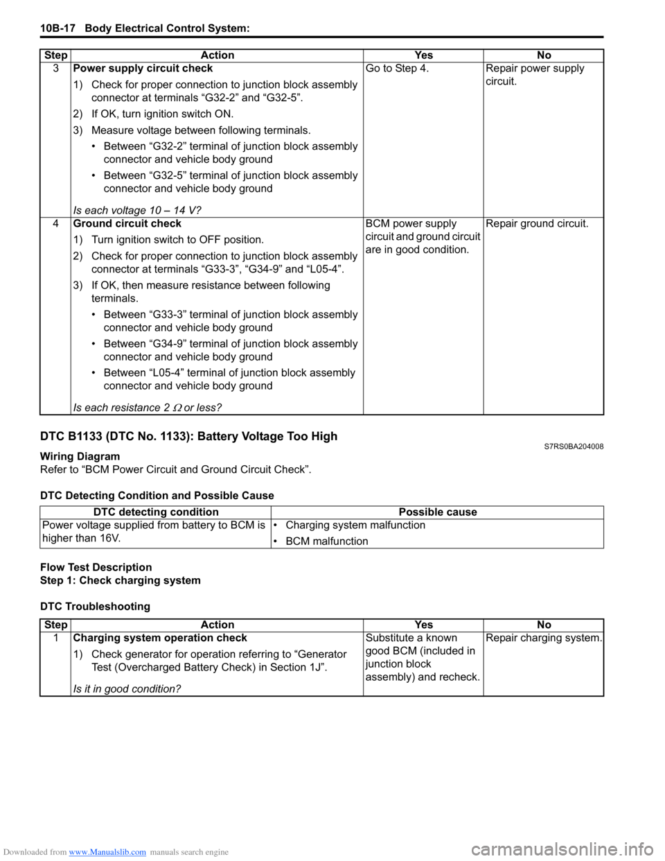
DTC Detecting Conditi on and Possible Cause
Flow Test Description
Step 1: Check charging system
DTC Troubleshooting 3
Power supply circuit check
1) Check for proper connection to junction block assembly
connector at terminals “G32-2” and “G32-5”.
2) If OK, turn ignition switch ON.
3) Measure voltage between following terminals. • Between “G32-2” terminal of junction block assembly connector and vehicle body ground
• Between “G32-5” terminal of junction block assembly connector and vehicle body ground
Is each voltage 10 – 14 V? Go to Step 4. Repair power supply
circuit.
4 Ground circuit check
1) Turn ignition switch to OFF position.
2) Check for proper connection to junction block assembly
connector at terminals “G33-3”, “G34-9” and “L05-4”.
3) If OK, then measure resistance between following terminals.
• Between “G33-3” terminal of junction block assembly connector and vehicle body ground
• Between “G34-9” terminal of junction block assembly connector and vehicle body ground
• Between “L05-4” terminal of junction block assembly connector and vehicle body ground
Is each resistance 2
Ω or less? BCM power supply
circuit and ground circuit
are in good condition.
Repair ground circuit.
Step Action Yes No
DTC detecting condition
Possible cause
Power voltage supplied from battery to BCM is
higher than 16V. • Charging system malfunction
• BCM malfunction
Step
Action YesNo
1 Charging system operation check
1) Check generator for operation referring to “Generator
Test (Overcharged Battery Check) in Section 1J”.
Is it in good condition? Substitute a known
good BCM (included in
junction block
assembly) and recheck.
Repair charging system.