2008 SUZUKI SWIFT Section 7b
[x] Cancel search: Section 7bPage 945 of 1496
Downloaded from www.Manualslib.com manuals search engine Heater and Ventilation: 7A-9
Blower Speed Selector InspectionS7RS0B7106010
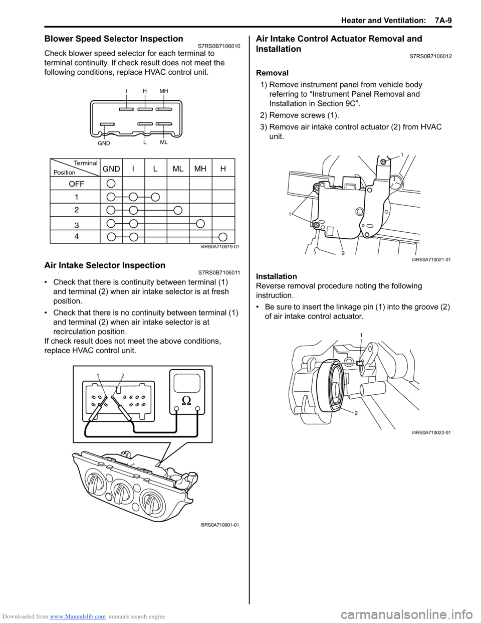
Check blower speed selector for each terminal to
terminal continuity. If check result does not meet the
following conditions, replace HVAC control unit.
Air Intake Selector InspectionS7RS0B7106011
• Check that there is continuity between terminal (1) and terminal (2) when air intake selector is at fresh
position.
• Check that there is no continuity between terminal (1) and terminal (2) when air intake selector is at
recirculation position.
If check result does not meet the above conditions,
replace HVAC control unit.
Air Intake Control Actuator Removal and
Installation
S7RS0B7106012
Removal
1) Remove instrument panel from vehicle body referring to “Instrum ent Panel Removal and
Installation in Section 9C”.
2) Remove screws (1).
3) Remove air intake control actuator (2) from HVAC unit.
Installation
Reverse removal procedure noting the following
instruction.
• Be sure to insert the linkage pin (1) into the groove (2) of air intake control actuator.
IHMH
GND LML
PositionTerminalI
OFF 1
2
3
4 LMLMHHGND
I4RS0A710019-01
1
2
I5RS0A710001-01
1 1
2
I4RS0A710021-01
1
2
I4RS0A710022-01
Page 946 of 1496
Downloaded from www.Manualslib.com manuals search engine 7A-10 Heater and Ventilation:
Air Intake Control Actuator InspectionS7RS0B7106013
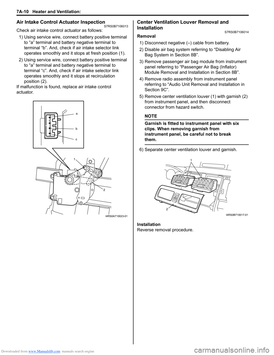
Check air intake control actuator as follows:1) Using service wire, connect battery positive terminal to “a” terminal and battery negative terminal to
terminal “b”. And, check if air intake selector link
operates smoothly and it st ops at fresh position (1).
2) Using service wire, connect battery positive terminal to “a” terminal and battery negative terminal to
terminal “c”. And, check if air intake selector link
operates smoothly and it stops at recirculation
position (2).
If malfunction is found, replace air intake control
actuator.
Center Ventilation Louver Removal and
Installation
S7RS0B7106014
Removal
1) Disconnect negative (–) cable from battery.
2) Disable air bag system referring to “Disabling Air Bag System in Section 8B”.
3) Remove passenger air bag module from instrument panel referring to “Passenger Air Bag (Inflator)
Module Removal and Installation in Section 8B”.
4) Remove radio assembly from instrument panel referring to “Audio Unit Re moval and Installation in
Section 9C”.
5) Remove center ventilation louver (1) with garnish (2) from instrument panel, and then disconnect
connector from hazard switch.
NOTE
Garnish is fitted to in strument panel with six
clips. When removing garnish from
instrument panel, be careful not to break
them.
6) Separate center ventilation louver and garnish.
Installation
Reverse removal procedure.
a
b
c
1
2
I4RS0A710023-01
1
2
I4RS0B710017-01
Page 947 of 1496
Downloaded from www.Manualslib.com manuals search engine Heater and Ventilation: 7A-11
Side Ventilation Louver Removal and
Installation
S7RS0B7106015
Driver side ventilation louver
Removal1) Disconnect negative (–) cable from battery.
2) Disable air bag system referring to “Disabling Air Bag System in Section 8B”.
3) Remove steering column hol e cover from instrument
panel.
4) Remove combination meter cluster panel from instrument panel, and then disconnect connectors
from front fog lamp switch, illumination cancel switch
and headlight leveling switch (if equipped) of
combination meter cluster panel.
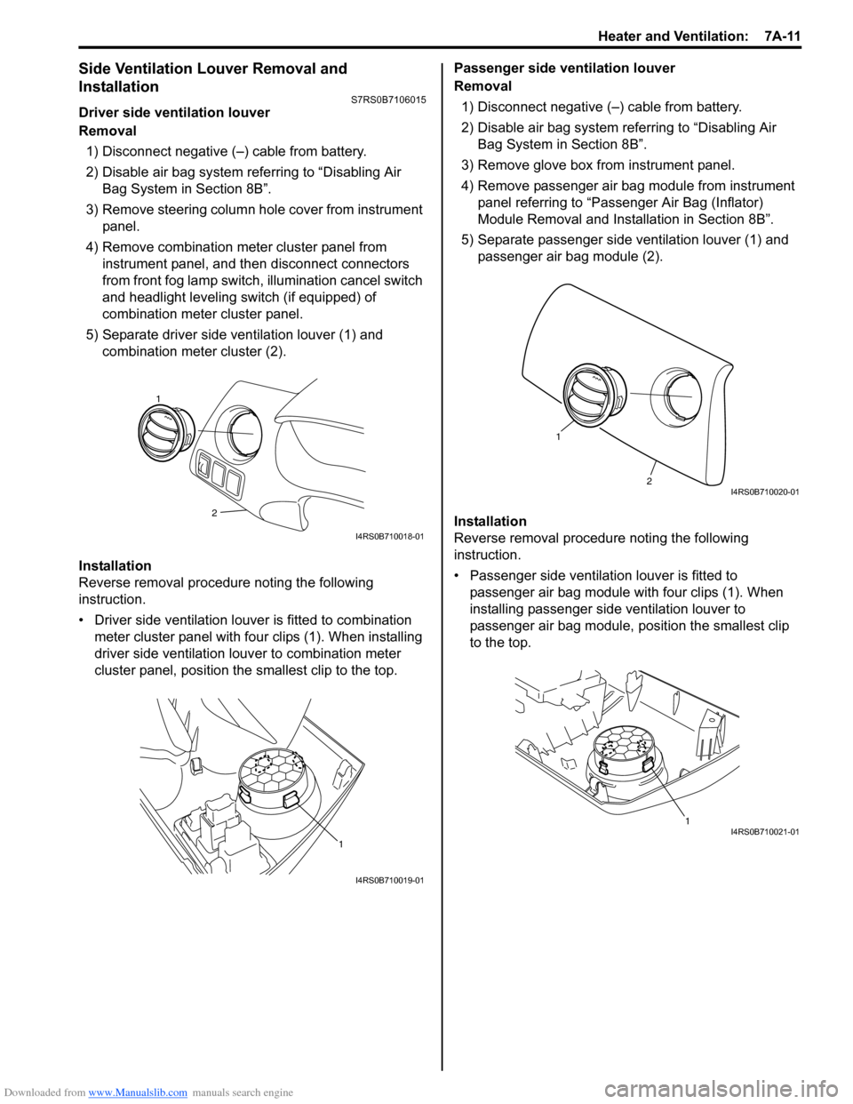
5) Separate driver side ventilation louver (1) and combination meter cluster (2).
Installation
Reverse removal procedure noting the following
instruction.
• Driver side ventilation louver is fitted to combination meter cluster panel with four clips (1). When installing
driver side ventilation louv er to combination meter
cluster panel, position the smallest clip to the top. Passenger side ventilation louver
Removal
1) Disconnect negative (–) cable from battery.
2) Disable air bag system referring to “Disabling Air Bag System in Section 8B”.
3) Remove glove box from instrument panel.
4) Remove passenger air bag module from instrument panel referring to “Passenger Air Bag (Inflator)
Module Removal and Installation in Section 8B”.
5) Separate passenger side ventilation louver (1) and passenger air bag module (2).
Installation
Reverse removal procedure noting the following
instruction.
• Passenger side ventilation louver is fitted to passenger air bag module with four clips (1). When
installing passenger side ventilation louver to
passenger air bag module, position the smallest clip
to the top.
2
1
I4RS0B710018-01
1
I4RS0B710019-01
2
1
I4RS0B710020-01
1I4RS0B710021-01
Page 952 of 1496
Downloaded from www.Manualslib.com manuals search engine 7B-4 Air Conditioning System: Manual Type
Sub-Cool A/C System DescriptionS7RS0B7211003
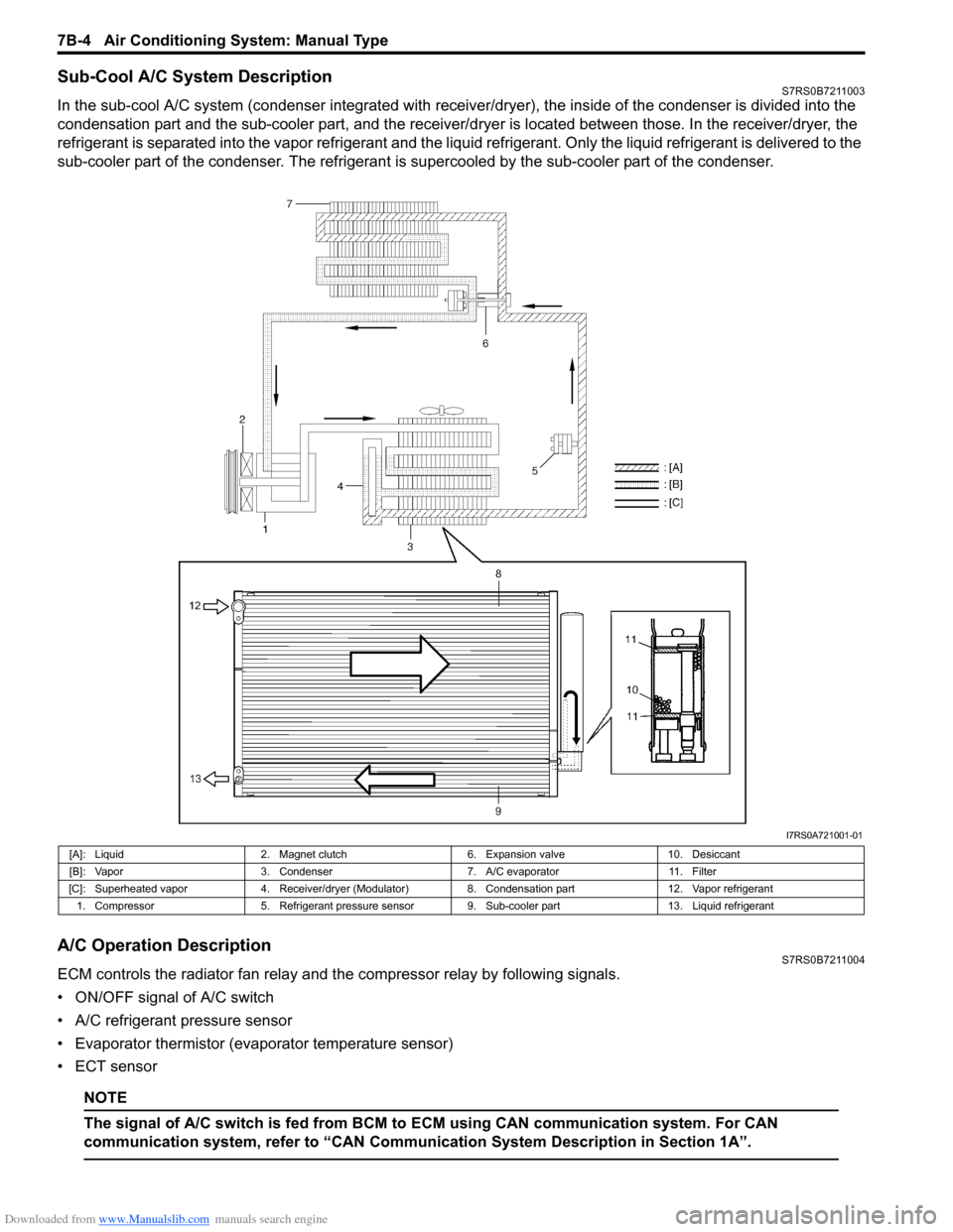
In the sub-cool A/C system (condenser integrated with receiver/dryer), the inside of the condenser is divided into the
condensation part and the sub-cooler part, and the receiver/dryer is located between those. In the receiver/dryer, the
refrigerant is separated into the vapor refrigerant and the liqui d refrigerant. Only the liquid refrigerant is delivered to the
sub-cooler part of the condenser. The refrigerant is supercooled by the sub-cooler part of the condenser.
A/C Operation DescriptionS7RS0B7211004
ECM controls the radiator fan relay and the compressor relay by following signals.
• ON/OFF signal of A/C switch
• A/C refrigerant pressure sensor
• Evaporator thermistor (evaporator temperature sensor)
• ECT sensor
NOTE
The signal of A/C swit ch is fed from BCM to ECM usin g CAN communication system. For CAN
communication system, refer to “CAN Communication System Description in Section 1A”.
I7RS0A721001-01
[A]: Liquid 2. Magnet clutch 6. Expansion valve10. Desiccant
[B]: Vapor 3. Condenser 7. A/C evaporator11. Filter
[C]: Superheated vapor 4. Receiver/dryer (Modulator) 8. Condensation part12. Vapor refrigerant
1. Compressor 5. Refrigerant pressure sensor 9. Sub-cooler part 13. Liquid refrigerant
Page 955 of 1496
Downloaded from www.Manualslib.com manuals search engine Air Conditioning System: Manual Type 7B-7
Diagnostic Information and Procedures
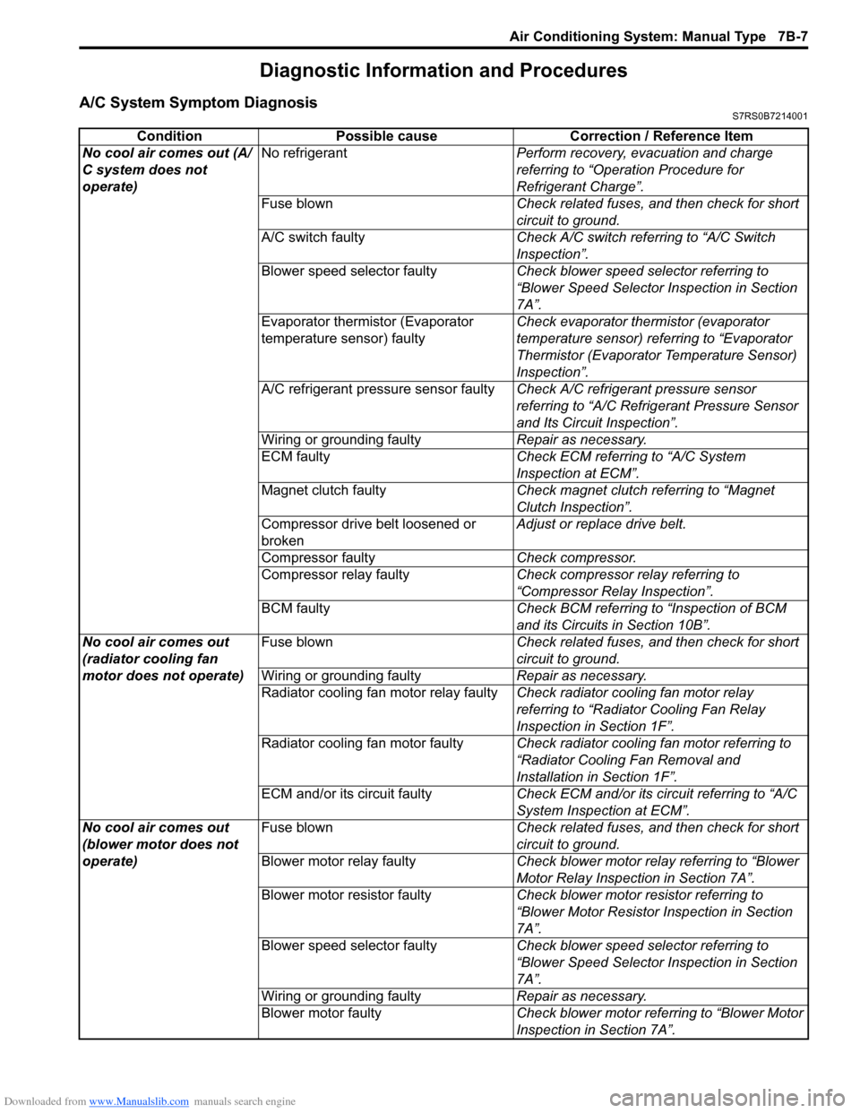
A/C System Symptom DiagnosisS7RS0B7214001
ConditionPossible cause Correction / Reference Item
No cool air comes out (A/
C system does not
operate) No refrigerant
Perform recovery, evacuation and charge
referring to “Operation Procedure for
Refrigerant Charge”.
Fuse blown Check related fuses, and then check for short
circuit to ground.
A/C switch faulty Check A/C switch referring to “A/C Switch
Inspection”.
Blower speed selector faulty Check blower speed selector referring to
“Blower Speed Selector Inspection in Section
7A”.
Evaporator thermistor (Evaporator
temperature sensor) faulty Check evaporator thermistor (evaporator
temperature sensor) referring to “Evaporator
Thermistor (Evaporator Temperature Sensor)
Inspection”.
A/C refrigerant pressure sensor faulty Check A/C refrigerant pressure sensor
referring to “A/C Refrigerant Pressure Sensor
and Its Circuit Inspection”.
Wiring or grounding faulty Repair as necessary.
ECM faulty Check ECM referring to “A/C System
Inspection at ECM”.
Magnet clutch faulty Check magnet clutch referring to “Magnet
Clutch Inspection”.
Compressor drive belt loosened or
broken Adjust or replace drive belt.
Compressor faulty Check compressor.
Compressor relay faulty Check compressor relay referring to
“Compressor Relay Inspection”.
BCM faulty Check BCM referring to “Inspection of BCM
and its Circuits in Section 10B”.
No cool air comes out
(radiator cooling fan
motor does not operate) Fuse blown
Check related fuses, and then check for short
circuit to ground.
Wiring or grounding faulty Repair as necessary.
Radiator cooling fan motor relay faulty Check radiator cooling fan motor relay
referring to “Radiator Cooling Fan Relay
Inspection in Section 1F”.
Radiator cooling fan motor faulty Check radiator cooling fan motor referring to
“Radiator Cooling Fan Removal and
Installation in Section 1F”.
ECM and/or its circuit faulty Check ECM and/or its circuit referring to “A/C
System Inspection at ECM”.
No cool air comes out
(blower motor does not
operate) Fuse blown
Check related fuses, and then check for short
circuit to ground.
Blower motor relay faulty Check blower motor relay referring to “Blower
Motor Relay Inspection in Section 7A”.
Blower motor resistor faulty Check blower motor resistor referring to
“Blower Motor Resistor Inspection in Section
7A”.
Blower speed selector faulty Check blower speed selector referring to
“Blower Speed Selector Inspection in Section
7A”.
Wiring or grounding faulty Repair as necessary.
Blower motor faulty Check blower motor referring to “Blower Motor
Inspection in Section 7A”.
Page 956 of 1496
Downloaded from www.Manualslib.com manuals search engine 7B-8 Air Conditioning System: Manual Type
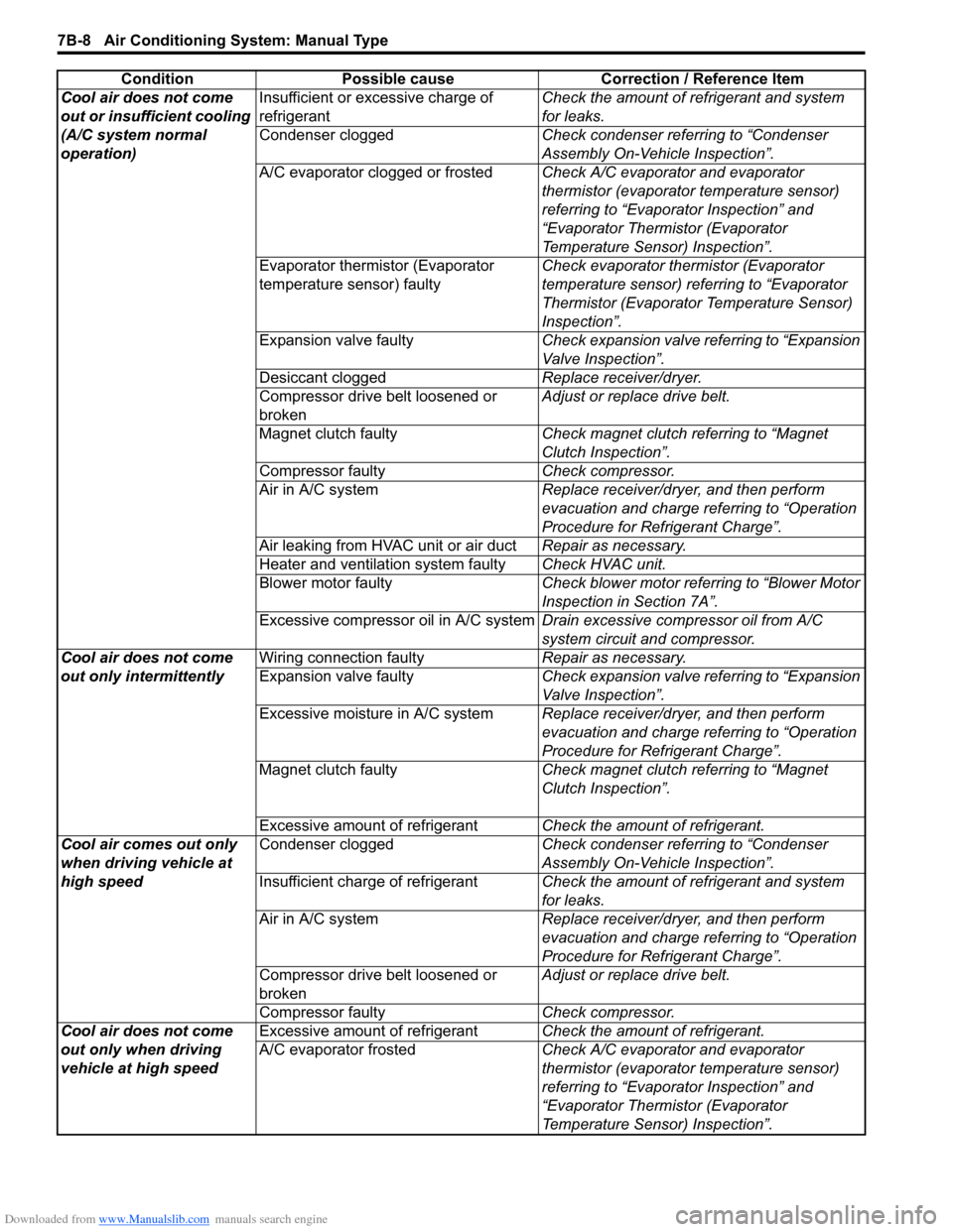
Cool air does not come
out or insufficient cooling
(A/C system normal
operation)Insufficient or excessive charge of
refrigerant
Check the amount of refrigerant and system
for leaks.
Condenser clogged Check condenser referring to “Condenser
Assembly On-Vehicle Inspection”.
A/C evaporator clogged or frosted Check A/C evaporator and evaporator
thermistor (evaporator temperature sensor)
referring to “Evaporator Inspection” and
“Evaporator Thermistor (Evaporator
Temperature Sensor) Inspection”.
Evaporator thermistor (Evaporator
temperature sensor) faulty Check evaporator thermistor (Evaporator
temperature sensor) referring to “Evaporator
Thermistor (Evaporator Temperature Sensor)
Inspection”.
Expansion valve faulty Check expansion valve referring to “Expansion
Valve Inspection”.
Desiccant clogged Replace receiver/dryer.
Compressor drive belt loosened or
broken Adjust or replace drive belt.
Magnet clutch faulty Check magnet clutch referring to “Magnet
Clutch Inspection”.
Compressor faulty Check compressor.
Air in A/C system Replace receiver/dryer, and then perform
evacuation and charge referring to “Operation
Procedure for Refrigerant Charge”.
Air leaking from HVAC unit or air duct Repair as necessary.
Heater and ventilation system faulty Check HVAC unit.
Blower motor faulty Check blower motor referring to “Blower Motor
Inspection in Section 7A”.
Excessive compressor oil in A/C system Drain excessive compressor oil from A/C
system circuit and compressor.
Cool air does not come
out only intermittently Wiring connection faulty
Repair as necessary.
Expansion valve faulty Check expansion valve referring to “Expansion
Valve Inspection”.
Excessive moisture in A/C system Replace receiver/dryer, and then perform
evacuation and charge referring to “Operation
Procedure for Refrigerant Charge”.
Magnet clutch faulty Check magnet clutch referring to “Magnet
Clutch Inspection”.
Excessive amount of refrigerant Check the amount of refrigerant.
Cool air comes out only
when driving vehicle at
high speed Condenser clogged
Check condenser referring to “Condenser
Assembly On-Vehicle Inspection”.
Insufficient charge of refrigerant Check the amount of refrigerant and system
for leaks.
Air in A/C system Replace receiver/dryer, and then perform
evacuation and charge referring to “Operation
Procedure for Refrigerant Charge”.
Compressor drive belt loosened or
broken Adjust or replace drive belt.
Compressor faulty Check compressor.
Cool air does not come
out only when driving
vehicle at high speed Excessive amount of refrigerant
Check the amount of refrigerant.
A/C evaporator frosted Check A/C evaporator and evaporator
thermistor (evaporator temperature sensor)
referring to “Evaporator Inspection” and
“Evaporator Thermistor (Evaporator
Temperature Sensor) Inspection”.
Condition Possible cause Correction / Reference Item
Page 957 of 1496
Downloaded from www.Manualslib.com manuals search engine Air Conditioning System: Manual Type 7B-9
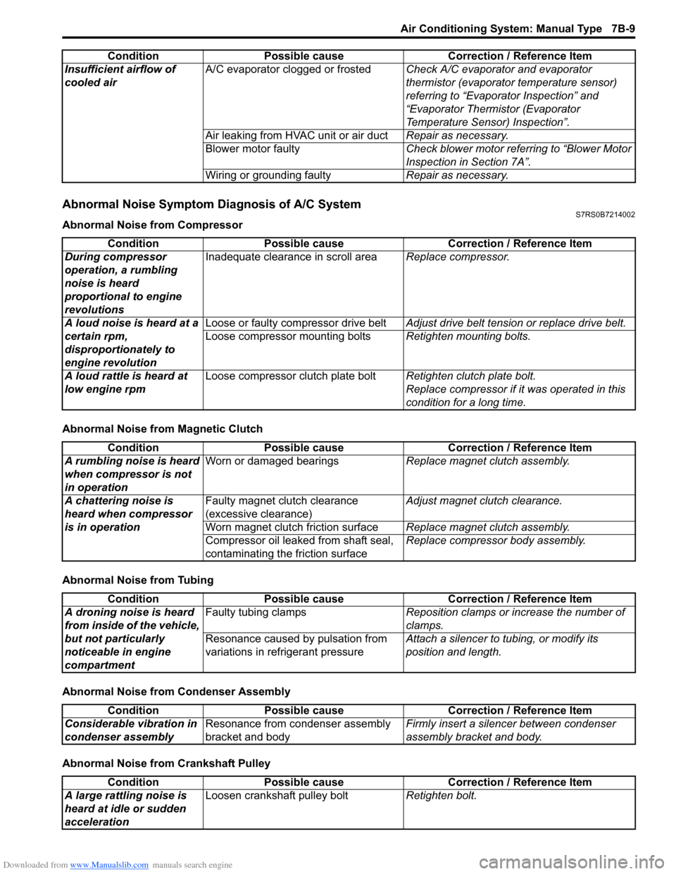
Abnormal Noise Symptom Diagnosis of A/C SystemS7RS0B7214002
Abnormal Noise from Compressor
Abnormal Noise from Magnetic Clutch
Abnormal Noise from Tubing
Abnormal Noise from Condenser Assembly
Abnormal Noise from Crankshaft PulleyInsufficient airflow of
cooled air
A/C evaporator clogged or frosted
Check A/C evaporator and evaporator
thermistor (evaporator temperature sensor)
referring to “Evaporator Inspection” and
“Evaporator Thermistor (Evaporator
Temperature Sensor) Inspection”.
Air leaking from HVAC unit or air duct Repair as necessary.
Blower motor faulty Check blower motor referring to “Blower Motor
Inspection in Section 7A”.
Wiring or grounding faulty Repair as necessary.
Condition Possible cause Correction / Reference Item
Condition
Possible cause Correction / Reference Item
During compressor
operation, a rumbling
noise is heard
proportional to engine
revolutions Inadequate clearance in scroll area
Replace compressor.
A loud noise is heard at a
certain rpm,
disproportionately to
engine revolution Loose or faulty compressor drive belt
Adjust drive belt tension or replace drive belt.
Loose compressor mounting bolts Retighten mounting bolts.
A loud rattle is heard at
low engine rpm Loose compressor clutch plate bolt
Retighten clutch plate bolt.
Replace compressor if it was operated in this
condition for a long time.
Condition Possible cause Correction / Reference Item
A rumbling noise is heard
when compressor is not
in operation Worn or damaged bearings
Replace magnet clutch assembly.
A chattering noise is
heard when compressor
is in operation Faulty magnet clutch clearance
(excessive clearance)
Adjust magnet clutch clearance.
Worn magnet clutch friction surface Replace magnet clutch assembly.
Compressor oil leaked from shaft seal,
contaminating the friction surface Replace compressor body assembly.
Condition
Possible cause Correction / Reference Item
A droning noise is heard
from inside of the vehicle,
but not particularly
noticeable in engine
compartment Faulty tubing clamps
Reposition clamps or increase the number of
clamps.
Resonance caused by pulsation from
variations in re frigerant pressure Attach a silencer to tubing, or modify its
position and length.
Condition
Possible cause Correction / Reference Item
Considerable vibration in
condenser assembly Resonance from condenser assembly
bracket and body Firmly insert a silenc
er between condenser
assembly bracket and body.
Condition Possible cause Correction / Reference Item
A large rattling noise is
heard at idle or sudden
acceleration Loosen crankshaft pulley bolt
Retighten bolt.
Page 960 of 1496
Downloaded from www.Manualslib.com manuals search engine 7B-12 Air Conditioning System: Manual Type
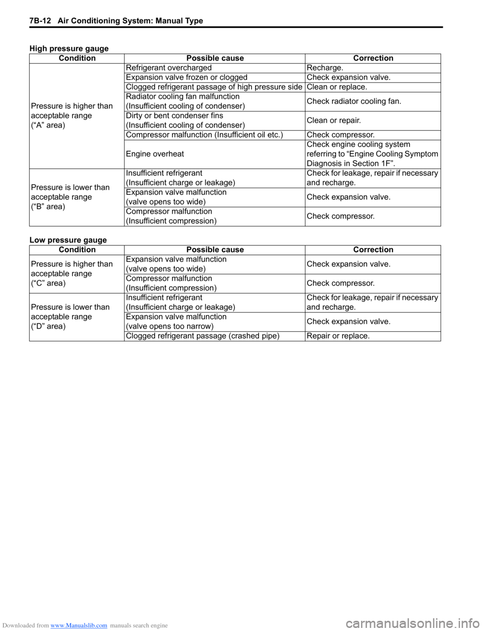
High pressure gauge
Low pressure gaugeCondition Possible cause Correction
Pressure is higher than
acceptable range
(“A” area) Refrigerant overcharged Recharge.
Expansion valve frozen or clogged Check expansion valve.
Clogged refrigerant passage of high pressure side Clean or replace.
Radiator cooling fan malfunction
(Insufficient cooling of condenser)
Check radiator cooling fan.
Dirty or bent condenser fins
(Insufficient cooling of condenser) Clean or repair.
Compressor malfunction (Insuffi cient oil etc.) Check compressor.
Engine overheat Check engine cooling system
referring to “Engin
e Cooling Symptom
Diagnosis in Section 1F”.
Pressure is lower than
acceptable range
(“B” area) Insufficient refrigerant
(Insufficient charge or leakage)
Check for leakage, repair if necessary
and recharge.
Expansion valve malfunction
(valve opens too wide) Check expansion valve.
Compressor malfunction
(Insufficient compression) Check compressor.
Condition Possible cause Correction
Pressure is higher than
acceptable range
(“C” area) Expansion valve malfunction
(valve opens too wide)
Check expansion valve.
Compressor malfunction
(Insufficient compression) Check compressor.
Pressure is lower than
acceptable range
(“D” area) Insufficient refrigerant
(Insufficient charge or leakage)
Check for leakage, repair if necessary
and recharge.
Expansion valve malfunction
(valve opens too narrow) Check expansion valve.
Clogged refrigerant passage (crashed pipe) Repair or replace.