2008 SUZUKI SWIFT diagnosis
[x] Cancel search: diagnosisPage 990 of 1496
Downloaded from www.Manualslib.com manuals search engine 7B-42 Air Conditioning System: Automatic Type
Abnormal Noise Symptom Diagnosis of A/C
System
S7RS0B7224002
Refer to “Abnormal Noise Symptom Diagnosis of A/C
System”.
DTC CheckS7RS0B7224003
Using SUZUKI Scan Tool1) Turn ignition switch to OFF position.
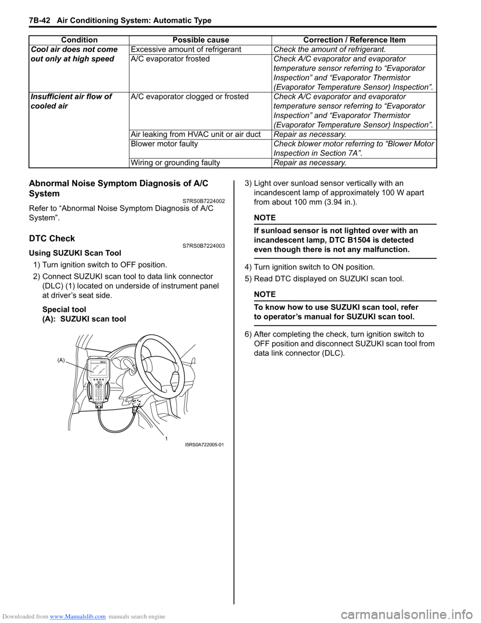
2) Connect SUZUKI scan tool to data link connector (DLC) (1) located on underside of instrument panel
at driver’s seat side.
Special tool
(A): SUZUKI scan tool 3) Light over sunload sensor vertically with an
incandescent lamp of approximately 100 W apart
from about 100 mm (3.94 in.).
NOTE
If sunload sensor is not lighted over with an
incandescent lamp, DTC B1504 is detected
even though there is not any malfunction.
4) Turn ignition switch to ON position.
5) Read DTC displayed on SUZUKI scan tool.
NOTE
To know how to use SUZUKI scan tool, refer
to operator’s manual for SUZUKI scan tool.
6) After completing the check, turn ignition switch to
OFF position and disconnect SUZUKI scan tool from
data link connector (DLC).
Cool air does not come
out only at high speed
Excessive amount of refrigerant
Check the amount of refrigerant.
A/C evaporator frosted Check A/C evaporator and evaporator
temperature sensor referring to “Evaporator
Inspection” and “Evaporator Thermistor
(Evaporator Temperature Sensor) Inspection”.
Insufficient air flow of
cooled air A/C evaporator clogged or frosted
Check A/C evaporator and evaporator
temperature sensor referring to “Evaporator
Inspection” and “Evaporator Thermistor
(Evaporator Temperature Sensor) Inspection”.
Air leaking from HVAC unit or air duct Repair as necessary.
Blower motor faulty Check blower motor referring to “Blower Motor
Inspection in Section 7A”.
Wiring or grounding faulty Repair as necessary.
Condition Possible cause Correction / Reference Item
(A)
1
I5RS0A722005-01
Page 992 of 1496
Downloaded from www.Manualslib.com manuals search engine 7B-44 Air Conditioning System: Automatic Type
3) Light over sunload sensor vertically with an incandescent lamp approximately 100 W apart from
about 100 mm (3.94 in.).
NOTE
If sunload sensor is not lighted over with an
incandescent lamp, DTC B1504 is detected
as current DTC even though there is not any
malfunction.
4) Turn ignition switch to ON position.
5) Erase DTC according to instructions displayed on SUZUKI scan tool.
NOTE
To know how to use SUZUKI scan tool, refer
to operator’s manual for SUZUKI scan tool.
6) After completing the clearance, turn ignition switch to OFF position, and then di sconnect SUZUKI scan
tool from DLC.
Not Using SUZUKI Scan Tool 1) Turn ignition switch to ON position.
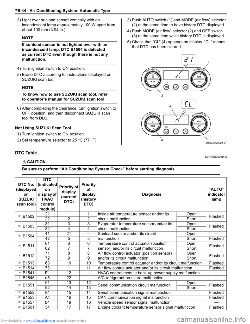
2) Set temperature selector to 25 °C (77 °F). 3) Push AUTO switch (1) and
MODE (air flow) selector
(2) at the same time to have history DTC displayed.
4) Push MODE (air flow) selector (2) and OFF switch (3) at the same time while history DTC is displayed.
5) Check that “CL” (4) appears on display. “CL” means that DTC has been cleared.
DTC TableS7RS0B7224005
CAUTION!
Be sure to perform “Air Conditioning Sy stem Check” before starting diagnosis.
1
2
3
2
4
I5RS0A722008-01
DTC No.
(displayed on
SUZUKI
scan tool) DTC
(indicated on
display of HVAC
control
module) Priority of
display
(current DTC) Priority
of
display
(history DTC) Diagnosis
“AUTO”
indicator lamp
�) B1502 21 1 1 Inside air temperature sensor and/or its
circuit malfunction Open
Flashed
22 2 2 Short
�) B1503 31 3 3 Evaporator temperature sensor and/or its
circuit malfunction Open
Flashed
32 4 4 Short
�) B1504 41 21 — Sunload sensor and/or its circuit
malfunction Open —
42 5 5 Short Flashed
�) B1511 61 6 6 Temperature control actuator (position
sensor) and/or its circuit malfunction Open
Flashed
62 7 7 Short
�) B1512 71 8 8 Air flow control actuator (position sensor)
and/or its circuit malfunction Open
Flashed
72 9 9 Short
�) B1513 63 10 10 Temperature control actuator and/or its circuit malfunction Flashed
�) B1514 73 11 11 Air flow control actuator and/or its circuit malfunction Flashed
�) B1541 E1 12 — HVAC control module back-up power supply malfunction —
�) B1546 d5 22 — A/C refrigerant pressure malfunction —
�) B1551 91 13 12
Serial communication circuit malfunction Open
Flashed
92 14 13 Short
�) B1552 94 15 14 Serial communication signal malfunction Flashed
�) B1553 A4 16 15 CAN communication signal malfunction Flashed
�) B1557 b4 19 16 Vehicle speed sensor signal malfunction —
�) B1561 54 17 17 Engine coolant temperature sensor signal malfunction Flashed
Page 993 of 1496
Downloaded from www.Manualslib.com manuals search engine Air Conditioning System: Automatic Type 7B-45
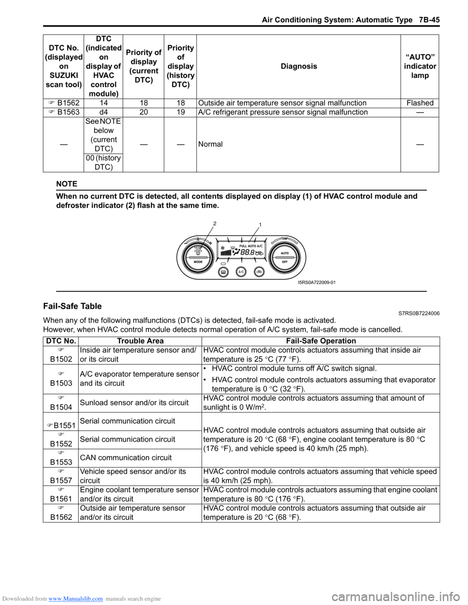
NOTE
When no current DTC is detected, all contents displayed on display (1) of HVAC control module and
defroster indicator (2) flash at the same time.
Fail-Safe TableS7RS0B7224006
When any of the following malfunctions (DTCs) is detected, fail-safe mode is activated.
However, when HVAC control module detects normal ope ration of A/C system, fail-safe mode is cancelled.
�)
B1562 14 18 18 Outside air temperatur e sensor signal malfunction Flashed
�) B1563 d4 20 19 A/C refrigerant pressure sensor signal malfunction —
— See NOTE
below
(current DTC) ——Normal —
00 (history DTC)
DTC No.
(displayed on
SUZUKI
scan tool) DTC
(indicated on
display of HVAC
control
module) Priority of
display
(current DTC) Priority
of
display
(history DTC) Diagnosis
“AUTO”
indicator lamp
1
2
I5RS0A722009-01
DTC No.
Trouble Area Fail-Safe Operation
�)
B1502 Inside air temperature sensor and/
or its circuit HVAC control module controls actu
ators assuming that inside air
temperature is 25 ° C (77 °F).
�)
B1503 A/C evaporator temperature sensor
and its circuit • HVAC control module turn
s off A/C switch signal.
• HVAC control module controls actu ators assuming that evaporator
temperature is 0 ° C (32 °F).
�)
B1504 Sunload sensor and/or its circuit HVAC control module controls actu
ators assuming that amount of
sunlight is 0 W/m
2.
�) B1551 Serial communication circuit
HVAC control module controls actuators assuming that outside air
temperature is 20 ° C (68 °F), engine coolant temperature is 80 °C
(176 °F), and vehicle speed is 40 km/h (25 mph).
�)
B1552 Serial communication circuit
�)
B1553 CAN communication circuit
�)
B1557 Vehicle speed sensor and/or its
circuit HVAC control module controls act
uators assuming that vehicle speed
is 40 km/h (25 mph).
�)
B1561 Engine coolant temperature sensor
and/or its circuit HVAC control module controls act
uators assuming that engine coolant
temperature is 80 ° C (176 °F).
�)
B1562 Outside air temperature sensor
and/or its circuit HVAC control module controls actu
ators assuming that outside air
temperature is 20 ° C (68 °F).
Page 995 of 1496
Downloaded from www.Manualslib.com manuals search engine Air Conditioning System: Automatic Type 7B-47
Scan Tool Data Definitions
TEMP CONT SWITCH (TEMPERATURE SELECTOR): Position of temperature control
selector of HVAC control module
CABIN TEMPERATURE: In-car temperature detected
by inside air temperature sensor installed in HVAC
control module
OUTSIDE AIR TEMP (OUTSIDE AIR TEMPERATURE): Outside air temperature
detected by outside air temperature sensor installed
in front bumper member
EVAPORATOR TEMP (EVAPORATOR TEMPERATURE): Temperature of air passed
through evaporator
COOLANT TEMP (ENGINE COOLANT TEMPERATURE): Engine coolant temperature
detected by engine coolant temperature sensor
SUN LOAD: Amount of sunlight detected by sunload
sensor installed on the driver side on the dashboard
MODE CONT SWITCH (MODE (AIR FLOW) SELECTOR): Position of air flow selector of HVAC
control module
FAN CONT SWITCH (BLOWER SPEED SELECTOR): Position of blower speed selector of HVAC control
module
FAN DESIRED VOLT: Voltage for blower motor AIR MIX POS SEN (TEMPERATURE CONTROL
ACTUATOR POSITI ON SENSOR): Input signal
from position sensor in temperature control actuator
MODE POS SENSOR (AIR FLOW CONTROL ACTUATOR POSITI ON SENSOR): Input signal
from position sensor in air flow control actuator
A/C CONT SIG (A/C SWITCH SIGNAL, ON or OFF): State of A/C switch
BLOWER LOAD SIG (BLO WER FAN LOAD SIGNAL,
ON or OFF): ON: Position of blower speed selector
is 1st position or more / OFF: Position of blower
speed selector is OFF position.
AIR INTAKE MODE (AUTO, FRE or REC): State of air
intake mode
REFRIGERANT PRESSURE (A/C REFRIGERANT ABSOLUTE PRESSURE): This parameter
indicates A/C refrigerant absolute pressure
calculated by ECM
A/C COMP CLUTCH (A/C COMPRESSOR MAGNET CLUTCH, ON or OFF): This parameter indicates
the state of the A/C switch
DFR INDICATOR (DEFROSTER INDICATOR LAMP, ON or OFF): State of defroster indicator lamp
VEHICLE SPEED: It is computed based on pulse
signals from vehicle speed sensor
Air Conditioning System CheckS7RS0B7224008
Step Action YesNo
1 Customer complaint analysis
1) Perform �)”Customer complaint analysis”.
Was customer complaint analysis performed? Go to Step 2.
Perform customer
complaint analysis.
2 Visual inspection
1) Perform �)“Visual inspection”.
Is there any faulty condition? Repair or replace
malfunction part.
Go to Step 3.
3 DTC check
1) Perform �)“DTC check”.
Is there any DTC code? Go to Step 4.
Go to Step 5.
4 Troubleshooting malfunction
1) Perform �) “Troubleshooting malfunction”.
Is there any faulty condition? Repair or replace
malfunction part, and go
to Step 7.
Go to Step 5.
5 Perform A/C system symptom diagnosis
1) Inspect and repair referri ng to “A/C System Symptom
Diagnosis”.
Is there any faulty condition? Repair or replace
malfunction part, and go
to Step 7.
Go to Step 6.
6 Check for intermittent problem
1) Check for intermittent troubles referring to “Intermittent
and Poor Connection Inspection in Section 00”.
Is there any faulty condition? Repair or replace
malfunction part, and go
to Step 7.
Go to Step 7.
7 Final confirmation test
1) Perform �) “Final confirmation test”.
Is there any malfunction code? Go to Step 4.
End.
Page 996 of 1496
Downloaded from www.Manualslib.com manuals search engine 7B-48 Air Conditioning System: Automatic Type
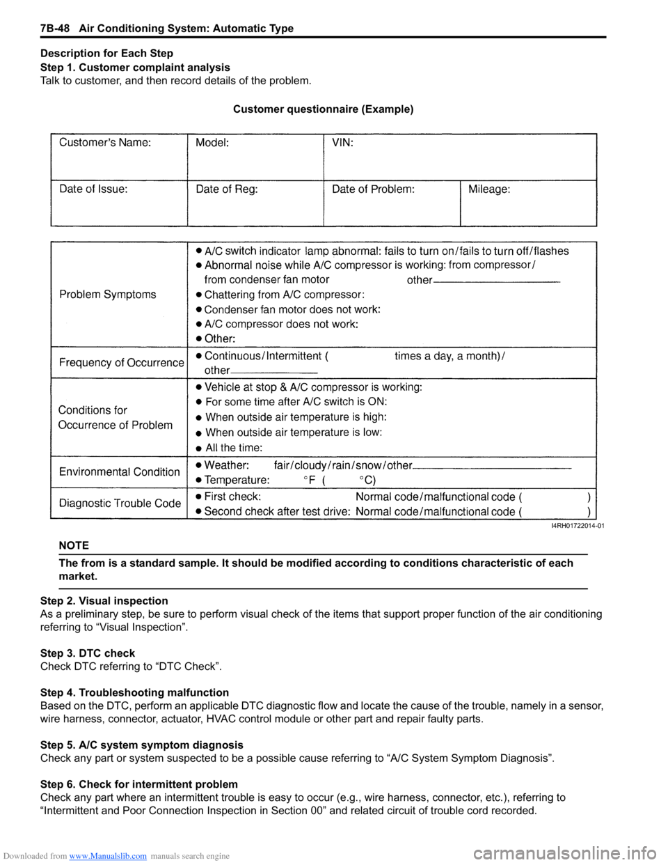
Description for Each Step
Step 1. Customer complaint analysis
Talk to customer, and then record details of the problem.
Customer questionnaire (Example)
NOTE
The from is a standard sample. It should be modified according to conditions characteristic of each
market.
Step 2. Visual inspection
As a preliminary step, be sure to perform visual check of th e items that support proper function of the air conditioning
referring to “Visual Inspection”.
Step 3. DTC check
Check DTC referring to “DTC Check”.
Step 4. Troubleshooting malfunction
Based on the DTC, perform an applicable DTC diagnostic flow and locate the cause of the trouble, namely in a sensor,
wire harness, connector, actuat or, HVAC control module or other part and repair faulty parts.
Step 5. A/C system symptom diagnosis
Check any part or system suspected to be a possible cause referring to “A/C System Symptom Diagnosis”.
Step 6. Check for intermittent problem
Check any part where an intermittent trouble is easy to oc cur (e.g., wire harness, connector, etc.), referring to
“Intermittent and Poor Connection Inspection in Sect ion 00” and related circuit of trouble cord recorded.
I4RH01722014-01
Page 1029 of 1496
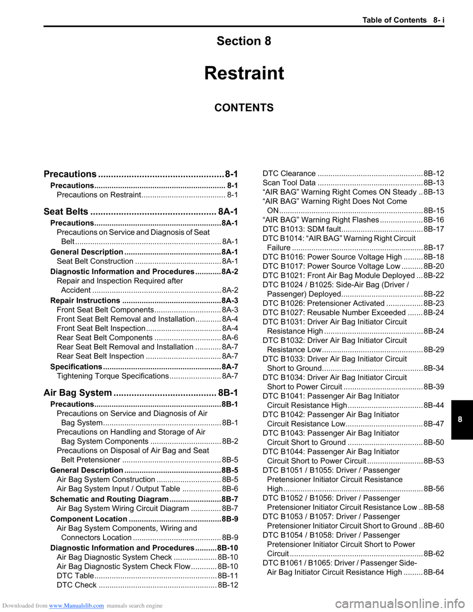
Downloaded from www.Manualslib.com manuals search engine Table of Contents 8- i
8
Section 8
CONTENTS
Restraint
Precautions ................................................. 8-1
Precautions............................................................. 8-1
Precautions on Restraint ....................................... 8-1
Seat Belts .......... ............................... ........ 8A-1
Precautions........................................................... 8A-1
Precautions on Service a nd Diagnosis of Seat
Belt .................................................................... 8A-1
General Description ............................................. 8A-1 Seat Belt Construction ........................................ 8A-1
Diagnostic Information and Procedures ............ 8A-2 Repair and Inspection Required after Accident ............................................................ 8A-2
Repair Instructions .............................................. 8A-3 Front Seat Belt Components ............................... 8A-3
Front Seat Belt Removal and Installation ............ 8A-4
Front Seat Belt Inspection ................................... 8A-4
Rear Seat Belt Components ............................... 8A-6
Rear Seat Belt Removal and Installation ............ 8A-7
Rear Seat Belt Inspection ................................... 8A-7
Specifications ....................................................... 8A-7
Tightening Torque Specifications ........................ 8A-7
Air Bag System ............... ......................... 8B-1
Precautions........................................................... 8B-1
Precautions on Service and Diagnosis of Air Bag System....................................................... 8B-1
Precautions on Handling and Storage of Air Bag System Components . ................................ 8B-2
Precautions on Disposal of Air Bag and Seat
Belt Pretensioner .............................................. 8B-5
General Description ............................................. 8B-5 Air Bag System Construction .............................. 8B-5
Air Bag System Input / Output Table .................. 8B-6
Schematic and Routing Diagram ........................ 8B-7 Air Bag System Wiring Circuit Diagram .............. 8B-7
Component Locatio n ........................................... 8B-9
Air Bag System Components, Wiring and Connectors Location ......................................... 8B-9
Diagnostic Information and Procedures .......... 8B-10 Air Bag Diagnostic System Check .................... 8B-10
Air Bag Diagnostic System Check Flow ............ 8B-10
DTC Table ......................................................... 8B-11
DTC Check ....................................................... 8B-12 DTC Clearance ................................................. 8B-12
Scan Tool Data ................................................. 8B-13
“AIR BAG” Warning Right Comes ON Steady .. 8B-13
“AIR BAG” Warning Right Does Not Come
ON ................................................................... 8B-15
“AIR BAG” Warning Right Flashes .................... 8B-16
DTC B1013: SDM fault...................................... 8B-17
DTC B1014: “AIR BAG” Warning Right Circuit Failure ............................................................. 8B-17
DTC B1016: Power Source Voltage High ......... 8B-18
DTC B1017: Power Source Voltage Low .......... 8B-20
DTC B1021: Front Air Bag Module Deployed ... 8B-22
DTC B1024 / B1025: Side-Air Bag (Driver / Passenger) Deployed...................................... 8B-22
DTC B1026: Pretensioner Activated ................. 8B-23
DTC B1027: Reusable Number Exceeded ....... 8B-24
DTC B1031: Driver Air Bag Initiator Circuit
Resistance High .............................................. 8B-24
DTC B1032: Driver Air Bag Initiator Circuit
Resistance Low ............................................... 8B-29
DTC B1033: Driver Air Bag Initiator Circuit
Short to Ground............................................... 8B-34
DTC B1034: Driver Air Bag Initiator Circuit
Short to Power Circuit .... ................................. 8B-39
DTC B1041: Passenger Air Bag Initiator Circuit Resistance High ................................... 8B-44
DTC B1042: Passenger Air Bag Initiator Circuit Resistance Low.................................... 8B-47
DTC B1043: Passenger Air Bag Initiator Circuit Short to Ground ................................... 8B-50
DTC B1044: Passenger Air Bag Initiator Circuit Short to Power Circ uit .......................... 8B-53
DTC B1051 / B1055: Driver / Passenger Pretensioner Initiator Circuit Resistance
High ................................................................. 8B-56
DTC B1052 / B1056: Driver / Passenger Pretensioner Initiator Circu it Resistance Low .. 8B-58
DTC B1053 / B1057: Driver / Passenger Pretensioner Initiator Circuit Short to Ground .. 8B-60
DTC B1054 / B1058: Driver / Passenger Pretensioner Initiator Circuit Short to Power
Circuit .............................................................. 8B-62
DTC B1061 / B1065: Driver / Passenger Side- Air Bag Initiator Circuit Resistance High ......... 8B-64
Page 1031 of 1496
Downloaded from www.Manualslib.com manuals search engine Precautions: 8-1
Restraint
Precautions
Precautions
Precautions on RestraintS7RS0B8000001
Air Bag System Service Warning
Refer to “Air Bag System Service Warning in Section 00”.
Fastener Caution
Refer to “Fastener Caution in Section 00”.
Precautions on Service and Diagnosis of Seat Belt
Refer to “Precautions on Service and Diagnosis of Seat Belt in Section 8A”.
Precautions on Service and Diagnosis of Air Bag System
Refer to “Precautions on Service and Diagnosis of Air Bag System in Section 8B”.
Precautions on Handling and Storage of Air Bag Components
Refer to “Precautions on Handling and Storage of Air Bag System Components in Section 8B”.
Precautions on Disposal of Air Bag and Seat Belt Pretensioner
Refer to “Precautions on Disposal of Air Bag and Seat Belt Pretensioner in Section 8B”.
Page 1032 of 1496
Downloaded from www.Manualslib.com manuals search engine 8A-1 Seat Belts:
Restraint
Seat Belts
Precautions
Precautions on Service and Diagnosis of Seat
Belt
S7RS0B8100001
WARNING!
If replacing seat belt is necessary, replace
buckle and seat belt assembly together as a
set. This is for the reason of ensuring locking
of tongue plate with buckle. If these parts are
replaced individually, such a locking
condition may become unreliable. For this
reason, SUZUKI will supply only the spare
buckle and seat belt assembly in a set part.
Before servicing or replacing seat belts, refer to the
following precautionary items.
• Seat belts should be normal relative to strap retractor and buckle portions. • Keep sharp edges and damaging objects away from
belts.
• Avoid bending or damaging any portion of belt buckle or latch plate.
• Do not bleach or dye belt webbing. (Use only mild soap and lukewarm water to clean it.)
• When installing a seat belt anchor bolt, it should be tightened by hand at first to prevent cross-threading
and then to specified torque.
• Do not attempt any repair s on retractor mechanisms
or retractor covers. Replace defective assemblies with
new replacement parts.
• Keep belts dry and clean at all times.
• If there exist any parts in question, replace such parts.
• Replace belts whose webbing is cut or otherwise damaged.
• Do not put anything into trim panel opening which seat belt webbing passes through.
General Description
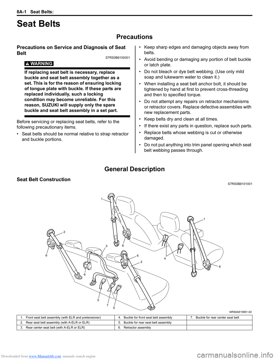
Seat Belt ConstructionS7RS0B8101001
1
1
6
6
6
5
5
7
6
6
2
2
3
4
I4RS0A810001-02
1. Front seat belt assembly (with ELR and pretensioner) 4. Buckle for front seat belt assembly7. Buckle for rear center seat belt
2. Rear seat belt assembly (with A-ELR or ELR) 5. Buckle for rear seat belt assembly
3. Rear center seat belt (with A-ELR or ELR) 6. Retractor assembly