2008 SUZUKI SWIFT diagnosis
[x] Cancel search: diagnosisPage 869 of 1496

Downloaded from www.Manualslib.com manuals search engine Precautions: 6-1
Steeri ng
Precautions
Precautions
Precautions on SteeringS7RS0B6000001
Air Bag Warning
Refer to “Air Bag Warning in Section 00”.
Air Bag System Service Warning
Refer to “Air Bag System Service Warning in Section 00”.
Precautions for Steering Diagnosis
Refer to “Precautions for Steering Diagnosis in Section 6A”.
Service Precautions of Steering Wheel and Column
Refer to “Service Precautions of Steering Wheel and Column in Section 6B”.
P/S System Note
Refer to “Steering System Note in Section 6C”.
Page 870 of 1496

Downloaded from www.Manualslib.com manuals search engine 6A-1 Steering General Diagnosis:
Steeri ng
Steering General Diagnosis
Precautions
Precautions for Steering DiagnosisS7RS0B6100001
Since the problems in steering involve several systems, they must all be considered when diagnosing a complaint. To
avoid using the wrong symptom, always road test the vehicl e first. Proceed with the following preliminary inspection
and correct any defects which are found.
1) Inspect tires for proper pressure and uneven wear.
2) Raise vehicle on a hoist and inspect steering system for loose or damaged parts.
3) Spin front wheels. Inspect for out-of-round tires, out- of-balance tires, bent rims, loosen and/or rough wheel
bearings.
Page 871 of 1496

Downloaded from www.Manualslib.com manuals search engine Steering General Diagnosis: 6A-2
Diagnostic Information and Procedures
Steering Symptom DiagnosisS7RS0B6104001
ConditionPossible cause Correction / Reference Item
Hard steering Tire not adequately inflated Inflate tires to proper pressure.
Malfunction of power steering system Check and correct.
Bind in tie-rod end ball studs or lower
ball joints Replace tie-rod end or front suspension arm.
Disturbed front wheel alignment Check and adjust front wheel alignment.
Bind in steering column Repair or replace steering column.
Rack and pinion adjustment Check and adjustment rack and pinion torque.
Too much play in steering Wheel bearings worn Replace wheel bearing.
Loose steering gear case bolts Tighten gear case bolts.
Faulty steering gear case assembly Replace steering gear case assembly.
Worn steering shaft joints Replace joint.
Worn tie-rod ends or tie-rod inside ball
joints Replace tie-rod end or tie-rod.
Worn lower ball joints Replace front suspension control arm.
Rack and pinion adjustment Check and adjustment rack and pinion torque.
Poor return ability Bind in tie-rod end ball studs Replace tie-rod end.
Bind in ball joints Replace front suspension control arm.
Bind in steering column Repair or replace steering column.
Disturbed front end alignment Check and adjust front end alignment.
Faulty steering gear case assembly Replace steering gear case assembly.
Tires not adequately inflated Adjust tire pressure.
Rack and pinion adjustment Check and adjustment rack and pinion torque.
Rack and pinion noise
(Rattle or chuckle) Loose steering gear case bolts
Tighten steering gear case bolts.
Rack and pinion adjustment Check and adjustment rack and pinion torque.
Faulty steering gear case assembly Replace steering gear case assembly.
Broken or other wise damaged wheel
bearing(s) Replace wheel bearing(s).
Wander or poor steering
stability Mismatched or uneven tires
Replace or inflate tires to proper pressure.
Loosen ball joints and tie-rod ends Replace suspension control arm or tie-rod end.
Faulty struts or mountings Replace strut or repair mounting.
Loose stabilizer bar Tighten or replace stabilizer bar or bush.
Broken or sagging springs Replace spring.
Rack and pinion adjustment Check and adjustment rack and pinion torque.
Disturbed front wheel alignment Check and adjust front wheel alignment.
Faulty steering gear case assembly Replace steering gear case assembly.
Erratic steering when
braking Worn wheel bearing(s)
Replace wheel bearing(s).
Broken or sagging spring(s) Replace coil spring(s).
Wheel tires are inflated unequally Inflate tires to proper pressure.
Disturbed front wheel alignment Check and adjust front wheel alignment.
Brakes not working in unison Check and repair brake system.
Leaking caliper Repair or replace caliper.
Warped discs Replace brake disc.
Badly worn brake pads Replace brake pads.
Page 872 of 1496

Downloaded from www.Manualslib.com manuals search engine 6B-1 Steering Wheel and Column:
Steeri ng
Steering Wheel and Column
Precautions
Service Precautions of Steering Wheel and
Column
S7RS0B6200001
For service precautions, refer to “Precautions on Service
and Diagnosis of Air Bag System in Section 8B”.
Service and Diagnosis
For diagnosis and servicing, refer to “Precautions on
Service and Diagnosis of Air Bag System in Section 8B”.
Disabling Air Bag System
For disabling air bag system, refer to “Disabling Air Bag
System in Section 8B”. Enabling Air Bag System
For enabling air bag system, refer to “Enabling Air Bag
System in Section 8B”.
Handling and Storage
For handling and storage, refer to “Precautions on
Handling and Storage of Air Bag System Components in
Section 8B”.
Disposal
For disposal, refer to “Prec
autions on Disposal of Air
Bag and Seat Belt Pretensioner in Section 8B”.
General Description
Steering Wheel and Column ConstructionS7RS0B6201001
This double tube type steering column has the following three important features in addition to the steering function:
• The column is energy absorbing, desig ned to compress in a front-end collision.
• The ignition switch and lock are mounted conveniently on this column.
• With the column mounted lock, the ignition and steering op erations can be locked to inhibit theft of the vehicle.
To insure the energy absorbing action, it is important th at only the specified screws, bolts and nuts be used as
designated, and that they are tightened to the specified torque. When the column assembly is removed from the
vehicle, special care must be taken in handling it. Use of a steering wheel puller or a sharp blow on the end of the
steering shaft, leaning on the assembly, or dropping the a ssembly could shear the plastic shear pins which maintain
column length and position.
The driver air bag (inflator) module is one of the supplemental restraint (air bag) system components and is mounted
to the center of the steering wheel. During certain frontal crashes, the air bag system supplements the restraint of the
driver’s and passenger’s seat belts by deploying the air b ags. The air bag (inflator) module should be handled with
care to prevent accidental deployment. When servicing, be sure to observe “Precautions on Service and Diagnosis of
Air Bag System in Section 8B”.
Page 885 of 1496

Downloaded from www.Manualslib.com manuals search engine Power Assisted Steering System: 6C-3
EPS Diagnosis General DescriptionS7RS0B6301002
The P/S system in this vehicle is controlled by the P/S control module. T he P/S control module has an on-board
diagnostic system which detects a malfunction in this system. When diagnosing troubles, be sure to have full
understanding of the outline of “On-Board Diagnostic Sy stem Description” and each item in “Precautions in
Diagnosing Troubles”, and then execute diagnosis according to “EPS System Check”.
On-Board Diagnostic System DescriptionS7RS0B6301003
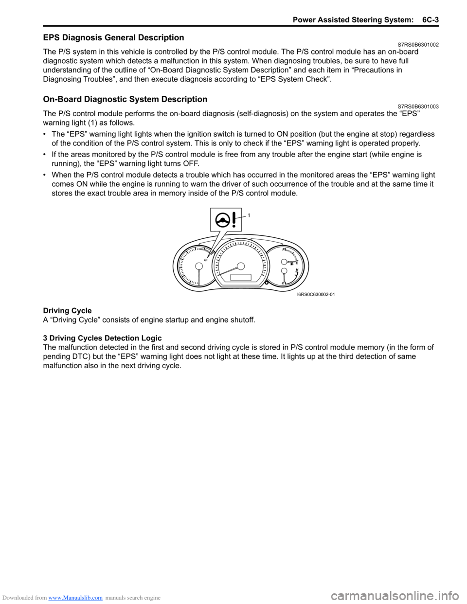
The P/S control module performs the on -board diagnosis (self-diagnosis) on the system and operates the “EPS”
warning light (1) as follows.
• The “EPS” warning light lights when the ignition switch is turned to ON position (but the engine at stop) regardless
of the condition of the P/S co ntrol system. This is only to check if the “EPS” warning light is operated properly.
• If the areas monitored by the P/S control module is free from any trouble after the engine start (while engine is
running), the “EPS” warning light turns OFF.
• When the P/S control module detects a trouble which has occurred in th e monitored areas the “EPS” warning light
comes ON while the engine is running to warn the driver of such occurrence of the trouble and at the same time it
stores the exact trouble area in memory inside of the P/S control module.
Driving Cycle
A “Driving Cycle” consists of en gine startup and engine shutoff.
3 Driving Cycles Detection Logic
The malfunction detected in the first and second driving cycl e is stored in P/S control module memory (in the form of
pending DTC) but the “EPS” wa rning light does not light at these time. It lights up at t he third detection of same
malfunction also in the next driving cycle.
1
I6RS0C630002-01
Page 888 of 1496

Downloaded from www.Manualslib.com manuals search engine 6C-6 Power Assisted Steering System:
NOTE
• As execution of “DTC Clearance” will clear all DTCs, be sure to record all DTCs before service.
• DTC C1122 is indicated when ignition switch is at ON position and engine is not running, it means
that nothing is abnormal.
• Current DTC and history DTC ca n be identified by condition of the “EPS” warning light.
“EPS” warning light operates as follows.
7 �) Rechecking and record of DTC
1) Recheck for DTC referring to “DTC Check”.
Is there any DTC(s)? Go to Step 9. Go to Step 10.
8 �) Steering symptom diagnosis and P/S system
symptom diagnosis
1) Check and repair according to “Steering Symptom Diagnosis in Section 6A” and “P/S System Symptom
Diagnosis”.
Are check and repair complete? Go to Step 11. Check and repair
malfunction part(s), and
go to Step 11.
9 �) Troubleshooting for DTC
1) Check and repair according to applicable DTC diag. flow.
Are check and repair complete? Go to Step 11. Check and repair
malfunction part(s), and
go to Step 11.
10 �) Intermittent problems check
1) Check for intermittent problems referring to “Intermittent Problems Check”.
Is there any faulty condition? Repair or replace
malfunction part(s), and
go to Step 11.
Go to Step 11.
11 �) Final confirmation test
1) Clear DTC if any.
2) Perform final confirmation test referring to “Final Confirmation Test”.
Is there any problem symptom, DTC or abnormal condition? Go to Step 6. End.
Step Action Yes No
Current DTC is set.
(Abnormality exists at
present.)
Only history DTC is set.
(Faulty condition occurred once
in the past, but normal condition
is detected at present.)
Current and history DTC
exist.
“EPS” warning light
after engine started Remains ON. Turns OFF. Remains ON.
Page 889 of 1496

Downloaded from www.Manualslib.com manuals search engine Power Assisted Steering System: 6C-7
Step 1: Customer Complaint Analysis
Record details of the problem (failure, co mplaint) and how it occurred as described by the customer. For this purpose,
use of such an inspection form will fac ilitate collecting information to the point required for proper analysis and
diagnosis. Check if the problem described in “Customer ques tionnaire” occurs actually in the vehicle if necessary.
(This step should be performed with the customer if possible.) Customer problem inspection form (Example)
NOTE
This form is a standard sample. It should be modified according to conditions characteristic of each
market.
I7RW01632004-02
Page 890 of 1496

Downloaded from www.Manualslib.com manuals search engine 6C-8 Power Assisted Steering System:
Step 2: DTC Check, Record and Clearance
First, check DTC, referring to “DTC Check”. If DTC is
indicated, print it or write them down and then clear them
by referring to “DTC Clearance”. DTC indicates
malfunction that occurred in the system but does not
indicate whether it exists now or it occurred in the past
and the normal condition has been restored now. To
check which case applies, check the symptom in
question according to Step 5 and recheck DTC
according to Step 6 and 7.
Attempt to diagnose a trouble based on DTC in this step
only or failure to clear the DTC in this step will lead to
incorrect diagnosis, trouble diagnosis of a normal circuit
or difficulty in troubleshooting.
Step 3 and 4: Visual Inspection
As a preliminary step, be sure to perform visual check of
the items that support proper function of the P/S system
referring to “Visual Inspection”.
Step 5: Trouble Symptom Confirmation
Based on information obtained in “Step 1: Customer
Complaint Analysis: ” and “S tep 2: DTC Check, Record
and Clearance: ”, confirm trouble symptoms. Also,
reconfirm trouble symptom by performing test drive and
turning steering wheel fully to right and left at stopped
vehicle.
Step 6 and 7: Rechecking and Record of DTC
Refer to “DTC Check” for checking procedure.
Step 8: Steering Symptom Diagnosis and P/S
System Symptom Diagnosis
Perform basic steering system check according to
“Steering Symptom Diagnosis in Section 6A” first. When
the end of the flow has been reached, check the parts of
the system suspected as a possible cause referring to
“P/S System Symptom Diagnosis” and based on
symptoms appearing on the vehicle (symptoms obtained
through steps of customer complaint analysis, trouble
symptom confirmation and/or basic P/S system check)
and repair or replace faulty parts, if any.
Step 9: Troubleshooting for DTC (See each DTC
Diag. Flow)
Based on the DTC indicated in Step 6 or 7 and referring
to the applicable DTC diag. flow, locate the cause of the
trouble, namely in a sensor, switch, wire harness,
connector, actuator, P/S control module or other part and
repair or replace faulty parts.
Step 10: Intermittent Problems Check
Check parts where an intermittent trouble is easy to
occur (e.g., wire harness, connector, etc.), referring to
“Intermittent and Poor Connection Inspection in Section
00” and related circuit of DTC recorded in Step 2. Step 11: Final Confirmation Test
Confirm that the problem symptom has gone and the P/
S system is free from any abnormal conditions. If what
has been repaired is related to the DTC, clear the DTC
once, perform DTC confirmation procedure and confirm
that no DTC is indicated.
“EPS” Warning Light CheckS7RS0B6304002
1) Turn ignition switch to ON position (without engine
running) and chec k if the “EPS” warning light (1)
lights up. If the light dose not light up, go to ““EPS”
Warning Light Does Not Come ON with Ignition
Switch Turned ON before Engine Starts” of the
diagnostic flows.
2) Start engine and check if the “EPS” warning light turns OFF. If light remains ON and no DTC is stored
in P/S control module, go to ““EPS” Warning Light
Remains ON Steady after Engine Starts” for
troubleshooting.
DTC CheckS7RS0B6304003
1) Turn ignition switch to OFF position.
2) Connect SUZUKI scan tool to data link connector (DLC) (1) located on underside of instrument panel
at driver’s seat side.
Special tool
(A): SUZUKI scan tool
1
I6RS0C630002-01
(A)
1
I4RS0B450003-01