2008 SUZUKI SWIFT 040
[x] Cancel search: 040Page 1128 of 1496
Downloaded from www.Manualslib.com manuals search engine 8B-90 Air Bag System:
NOTE
Upon completion of inspection and repair work, perform the following items.
• Reconnect all air bag system components, ensure all components are properly mounted.
• Clear DTCs referring to “DTC Clearance”, if any.
• Repeat “Air Bag Diagnostic System Check” to confirm that the trouble has been corrected.
DTC B1364 / B1368: Driver / Passenger Side Curtain-Air Bag Initiator Circuit Short to Power CircuitS7RS0B8204046
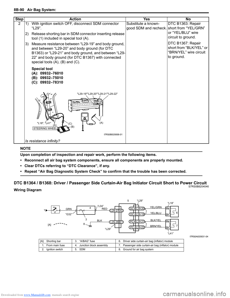
Wiring Diagram2 1) With ignition switch OFF, disconnect SDM connector
“L29”.
2) Release shorting bar in SDM connector inserting release tool (1) included in special tool (A).
3) Measure resistance between “L29-19” and body ground, and between “L29-20” and body ground (for DTC
B1363) or “L29-21” and body ground, and between “L29-
22” and body ground (for DTC B1367) with connected
special tools (A), (B) and (C).
Special tool
(A): 09932–76010
(B): 09932–75010
(C): 09932–78310
Is resistance infinity? Substitute a known-
good SDM and recheck.
DTC B1363: Repair
short from “YEL/GRN”
or “YEL/BLU” wire
circuit to ground.
DTC B1367: Repair
short from “BLK/YEL” or
“BRN/YEL” wire circuit
to ground.
Step Action Yes No
"L29-20""L29-21""L29-22"
"L29-19"
STEERING WHEEL(B)
(C)
(A)
"L18", "L41"
(A)
I7RS0B820006-01
1
2
3
GRN
RED
8
BLK
L29-27
L29-28 IG
E1
4
“L29”
“L04”
“G32”
“L29”
L29-20
DC+
L29-19
DC-YEL/BLU
YEL/GRN
56
“L18”
L29-21
PC+
L29-22
PC-BRN/YEL BLK/YEL7
“L41”[A]
I7RS0A820031-04
[A]: Shorting bar 3. “A/BAG” fuse 6. Driver side curtain-air bag (inflator) module
1. From main fuse 4. Junction block assembly 7. Passenger side curtain-air bag (inflator) module
2. Ignition switch 5. SDM 8. Ground for air bag system
Page 1131 of 1496
Downloaded from www.Manualslib.com manuals search engine Air Bag System: 8B-93
Contact Coil Cable and Its Circuit CheckS7RS0B8204047
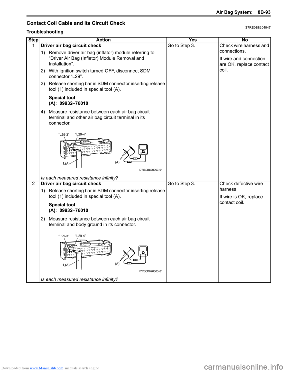
TroubleshootingStep Action Yes No 1 Driver air bag circuit check
1) Remove driver air bag (inflator) module referring to
“Driver Air Bag (Inflator) Module Removal and
Installation”.
2) With ignition switch turned OFF, disconnect SDM connector “L29”.
3) Release shorting bar in SDM connector inserting release tool (1) included in special tool (A).
Special tool
(A): 09932–76010
4) Measure resistance between each air bag circuit terminal and other air bag circuit terminal in its
connector.
Is each measured resistance infinity? Go to Step 3. Check wire harness and
connections.
If wire and connection
are OK, replace contact
coil.
2 Driver air bag circuit check
1) Release shorting bar in SDM connector inserting release
tool (1) included in special tool (A).
Special tool
(A): 09932–76010
2) Measure resistance between each air bag circuit terminal and body ground in its connector.
Is each measured resistance infinity? Go to Step 3. Check defective wire
harness.
If wire is OK, replace
contact coil.
“L29-4”
“L29-3”
1,(A)(A)
I7RS0B820003-01
“L29-4”
“L29-3”
1,(A)(A)
I7RS0B820003-01
Page 1133 of 1496
Downloaded from www.Manualslib.com manuals search engine Air Bag System: 8B-95
Inspection of Intermittent and Poor
Connections
S7RS0B8204048
Most intermittents are caused by faulty electrical
connections or wiring. When a check for proper
connection is requested in a diagnostic flow, perform
careful check of suspect circuits.
If any abnormality is found, repair or replace as a wire
harness assembly.
• Poor mating of connector halves, or terminals not fully seated in the connector body (backed out).
• Dirt or corrosion on the terminals. The terminals must be clean and free of any foreign material which could
impede proper terminal contact.
However, cleaning the terminal with a sand paper or
the like is prohibited.
• Damaged connector body, exposing the terminals to moisture and dirt, as well as not maintaining proper
terminal orientation with the component or mating
connector.
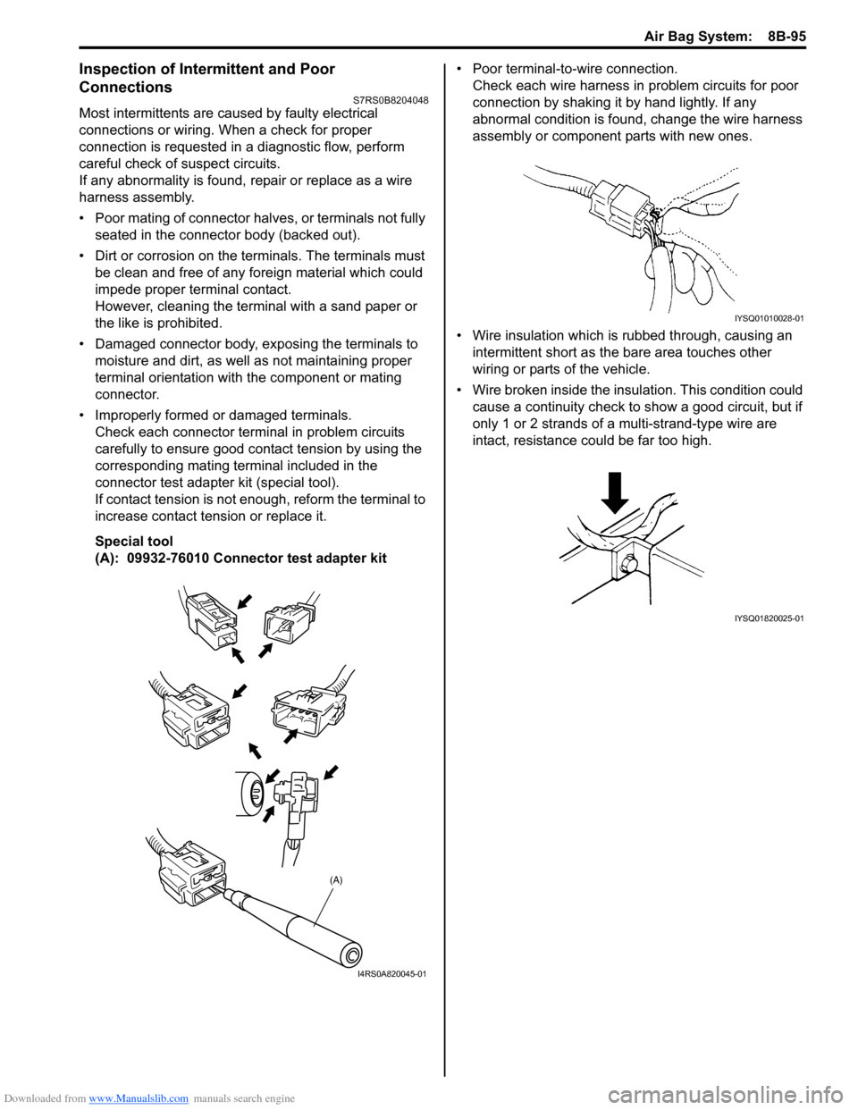
• Improperly formed or damaged terminals. Check each connector terminal in problem circuits
carefully to ensure good contact tension by using the
corresponding mating terminal included in the
connector test adapter kit (special tool).
If contact tension is not e nough, reform the terminal to
increase contact tension or replace it.
Special tool
(A): 09932-76010 Connector test adapter kit • Poor terminal-to-wire connection.
Check each wire harness in problem circuits for poor
connection by shaking it by hand lightly. If any
abnormal condition is found, change the wire harness
assembly or component parts with new ones.
• Wire insulation which is rubbed through, causing an intermittent short as the bare area touches other
wiring or parts of the vehicle.
• Wire broken inside the insulation. This condition could cause a continuity check to show a good circuit, but if
only 1 or 2 strands of a multi-strand-type wire are
intact, resistance could be far too high.
(A)
I4RS0A820045-01
IYSQ01010028-01
IYSQ01820025-01
Page 1134 of 1496
Downloaded from www.Manualslib.com manuals search engine 8B-96 Air Bag System:
Repair and Inspection Required after AccidentS7RS0B8204049
CAUTION!
• All air bag system components, including the electrical harness (component
mounting points), must be inspected after
an accident. If any components are
damaged or bent, they must be replaced
even if air bag system activation did not
occur.
• Never use air bag system parts from another vehicle.
• Do not attempt to service the parts below. Service of these parts is by replacement
only.
– Driver / Passenger air bag (inflator) modules
– Driver / Passenger side-air bag (inflator) modules
– Driver / Passenger side curtain-air bag (inflator) modules
– Driver / Passenger seat belt pretensioners
–Forward-sensor
– Driver / Passenger side-sensors
–SDM
– Contact coil and combination switch assembly
– Air bag wire harness in main harness, instrument panel harness and floor
harness.
• Proper operation of the sensors and air bag system requires that any repairs to the
vehicle structure return it to its original
production configuration.
CAUTION!
After detecting one time of such collision as
to meet deployment conditions, the SDM
must not be used.
Refer to “Air Bag Diagnostic System Check”
when checking the SDM.
Accident with Deployment / Activation – Component
Replacement
When driver and passenger air bags are deployed, the
following components must be replaced.
• Driver and passenger air bag (inflator) modules
• Driver and passenger seat belt pretensioners
• SDM after detecting such collision as to meet
deployment conditions
• Forward-sensor
• Instrument panel When side-air bag and side curtain-air bag are deployed,
the following components must be replaced.
• Deployed side-air bag (inflator) module
• Deployed side curtain-air bag (inflator) module
• Side-sensor
•SDM
Accident with or without Deployment / Activation –
Component Inspections
Certain air bag and restraint system components must
be inspected after any crash, whether the air bag system
activated or not. If any faul
ty condition is found in the
following checks, replace faulty part.
Those components are:
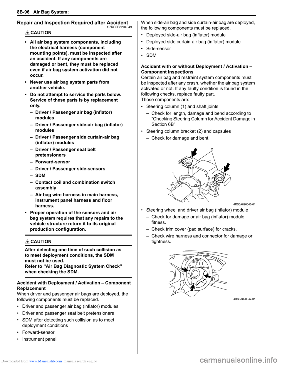
• Steering column (1) and shaft joints
– Check for length, damage and bend according to “Checking Steering Column for Accident Damage in
Section 6B”.
• Steering column bracket (2) and capsules – Check for damage and bent.
• Steering wheel and driver air bag (inflator) module – Check for damage or air bag (inflator) module fitness.
– Check trim cover (pad surface) for cracks.
– Check wire harness and connector for damage or tightness.
2
1
I4RS0A820046-01
I4RS0A820047-01
Page 1274 of 1496
Downloaded from www.Manualslib.com manuals search engine 9A-103 Wiring Systems:
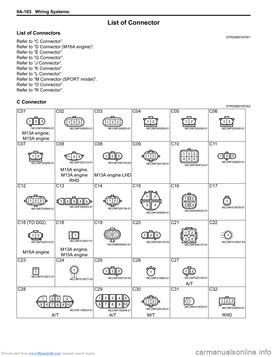
List of Connector
List of ConnectorsS7RS0B910F001
Refer to “C Connector”.
Refer to “D Connector (M16A engine)”.
Refer to “E Connector”.
Refer to “G Connector”.
Refer to “J Connector”.
Refer to “K Connector”.
Refer to “L Connector”.
Refer to “M Connector (SPORT model)”.
Refer to “O Connector”.
Refer to “R Connector”.
C ConnectorS7RS0B910F002
C01C02C03 C04 C05 C06
M13A engine, M15A engine
C07 C08C08 C09 C10 C11
M15A engine, M13A engine RHD M13A engine LHD
C12 C13C14 C15 C16 C17
C18 (TO D02) C18 C19C20C21C22
M16A engine M13A engine,
M15A engine
C23 C24C25 C26 C27
A/T
C28 C29C30C31C32
A/T A/TM/T RHD
1
23
MCONF030085-01
123
MCONF030055-01
123
MCONF030055-01
12
MCONF020266-01
12
MCONF020266-01
12
MCONF020266-01
12
MCONF020266-01
123
MCONF030123-01
123
MCONF030103-02
12
MCONF020156-01
123
456
MCONF060018-01
123
MCONF030062-01
123
MCONF030084-01
14325
MCONF050025-01
12
MCONF020156-01
12
34
MCONF040008-01
1
2
3 4
MCONF040024-01
1
MCONF010076-01
12
MCONF020310-01
1
MCONF010027-01
21
MCONM020042-01
12
3
MCONF030103-02
21
43
MCONF040127-01
1
MCONF010057-03
1MCONF010021-01
1
MCONF010077-03
123
MCONF030103-02
1
MCONF010054-01
1
2
MCONF020150-01
1
5678910 23 4
MCONF100053-01
1
2 5
6 7
103
84
9
MCONF100048-01
12
MCONF020156-01
1
MCONF010078-01
123
MCONF030040-01
Page 1275 of 1496
Downloaded from www.Manualslib.com manuals search engine Wiring Systems: 9A-104
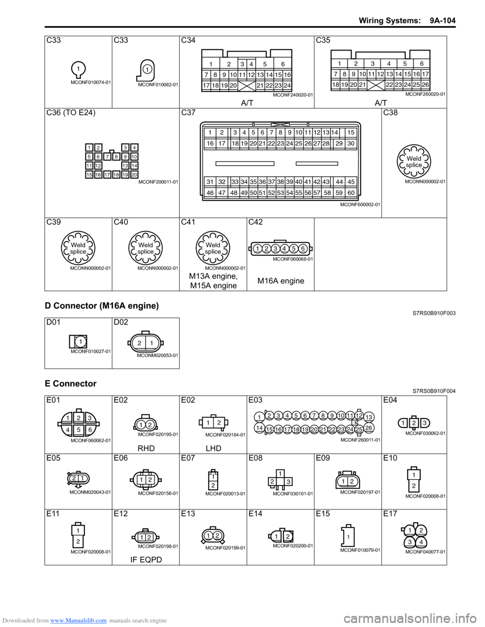
D Connector (M16A engine)S7RS0B910F003
E ConnectorS7RS0B910F004
C33C33C34 C35
A/T A/T
C36 (TO E24) C37 C38
C39 C40C41 C42
M13A engine, M15A engine M16A engine
D01 D02
E01 E02E02E03 E04
RHD LHD
E05 E06E07E08 E09E10
E11 E12E13 E14 E15 E17
IF EQPD
1
MCONF010074-01
1
MCONF010082-0117181920
7
1256
89101113141516
21222324
12
34
MCONF240020-01
181920 21
7 12345 68910
22232425
13141516
26
171112
MCONF260020-01
21
8
3
9765
131211
1819
4
10
14
20171615MCONF200011-01
12 3456
20 21
16 17 18 1978910
22 23 24 25 12
272613
28
31 32 33 34 35 36 50 51
46 47 48 49 37 38 39 40
52 53 54 5511
41
56
42
5743
5814 15 29 30
44 60 45
59
MCONF600002-01
Weld
splice
MCONN000002-01
Weld
splice
MCONN000002-01
Weld
splice
MCONN000002-01
Weld
splice
MCONN000002-01
1234 56
MCONF060068-01
1
MCONF010027-01
21
MCONM020053-01
1 2 3
4 5
6
MCONF060062-01
12
MCONF020195-01
12
MCONF020184-01
12345678910111213
14151617181920212223242526
MCONF260011-01
123
MCONF030062-01
21
MCONM020043-01
12
MCONF020156-01
1
2
MCONF020013-01
12 3
MCONF030101-01
21
MCONF020197-01
1
2
MCONF020008-01
1
2
MCONF020008-01
21
MCONF020198-01
12
MCONF020199-01
1
2
MCONF020200-01
1
MCONF010079-01
21
43
MCONF040077-01
Page 1276 of 1496
Downloaded from www.Manualslib.com manuals search engine 9A-105 Wiring Systems:
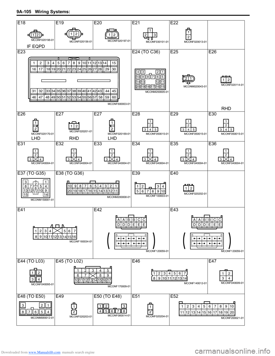
E18E19E20E21 E22
IF EQPD
E23 E24 (TO C36) E25E26
RHD
E26 E27E27E28 E29E30
LHD RHD LHD
E31 E32E33E34 E35E36
E37 (TO G35) E38 (TO G36) E39E40
E41 E42E43
E44 (TO L03) E45 (TO L02) E46E47
E48 (TO E50) E49 E50 (TO E48) E51E52
21
MCONF020198-01
12
MCONF020156-01
21
MCONF020197-01
12
3
MCONF030101-01
1
2
MCONF020013-01
123456
202116171819
78910
22232425
12
2726
13
28
313233343536
505146474849
37383940
52535455
11
41
56
42
57
43
58
1415
2930
44
60
45
59
MCONF600003-01
34
7
2
68910
121314
1716
1
5
11
15181920
MCONM200005-01
21
MCONM020043-01
21
MCONF020114-01
1
2
MCONF020170-01
21
MCONF020201-01
1
2
MCONF020169-01
1
2
345
MCONF050015-01
1
2
345
MCONF050015-01
1
2
345
MCONF050015-01
1
2
34
MCONF040004-01
1
2
34
MCONF040004-01
1
2
34
MCONF040004-01
1
2
34
MCONF040004-01
1
2
34
MCONF040004-01
1
2
34
MCONF040004-01
381371251015
14914
2611
MCONM150001-01
54 32 167910
20 19 18 17 16 15 14 13 12 118
MCONM200008-01
1 234
5 678 910
MCONF100003-01
21
MCONF020202-01
6
5
4
3
2
17
11
10
9
8 15
14
13
12 16
MCONF160034-01
CC
AABB
DE
DD
EE
MCONF120059-01
CC
AABB
DE
DD
EE
MCONF120059-01
12
34
MCONF040095-0110 1
6111415 16 171213
2
734
85
9
MCONF170009-01
12567
8
9 1011121314
34
MCONF140012-01
12
34
MCONF040009-01
21
7654
3
8
MCONM080012-01
1
2
MCONF020203-01
2
51
47 6
8
3
MCONF080014-01
1
2
MCONF020204-01
10
11 12 13 14 15 16 17 18 19 123456789
20
MCONF200021-01
Page 1277 of 1496
Downloaded from www.Manualslib.com manuals search engine Wiring Systems: 9A-106
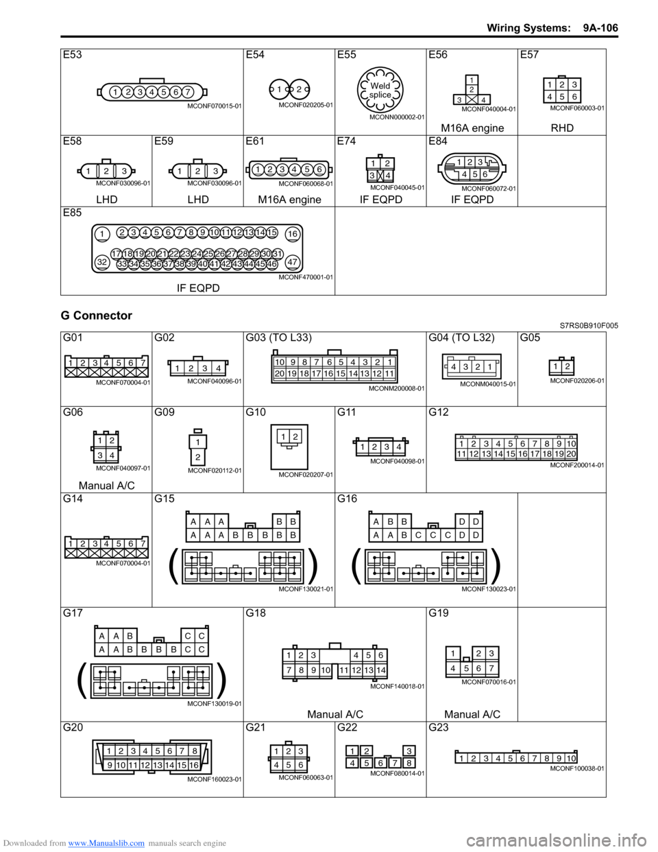
G ConnectorS7RS0B910F005
E53E54E55 E56E57
M16A engine RHD
E58 E59E61E74 E84
LHD LHD M16A engine IF EQPD IF EQPD
E85
IF EQPD
G01 G02G03 (TO L33) G04 (TO L32) G05
G06 G09G10G11G12
Manual A/C
G14 G15 G16
G17 G18G19
Manual A/C Manual A/C
G20 G21G22G23
1234567
MCONF070015-01
12
MCONF020205-01
Weld
splice
MCONN000002-01
1
2
34
MCONF040004-01
123
46 5
MCONF060003-01
1 23
MCONF030096-01
123
MCONF030096-01
1234 56
MCONF060068-01
1
34
2
MCONF040045-01
2
5
46
13
MCONF060072-01
21
3247
163451213141567891011
3334353643444546373839404142181719202128293031222324252627
MCONF470001-01
1234567
MCONF070004-01
1234
MCONF040096-01
54 32 167910
20 19 18 17 16 15 14 13 12 118
MCONM200008-01
12
34
MCONM040015-01
12
MCONF020206-01
12
34
MCONF040097-01
1
2
MCONF020112-01
21
MCONF020207-01
1234
MCONF040098-01
125678911 12 13 14 15 16 17 18 1910
2034
MCONF200014-01
1234567
MCONF070004-01
AAA BB
AAA B
BB
BB
( )
MCONF130021-01
ABB DD
AAB D
CC
CD
( )
MCONF130023-01
AAB CC
AAB C
BB
BC
( )
MCONF130019-01
123
78910
456
11121314
MCONF140018-01
3
7654
21
MCONF070016-01
1234567 8
9 10111213141516
MCONF160023-01
3
21
654
MCONF060063-01
2
51
47 6
8
3
MCONF080014-01
12345678910MCONF100038-01