2008 SUZUKI SWIFT flat tire
[x] Cancel search: flat tirePage 881 of 1496

Downloaded from www.Manualslib.com manuals search engine Steering Wheel and Column: 6B-10
5) Tighten new bolts (1) until head of each bolt is broken off.
6) Turn ignition key to “ACC” or “ON” position and check to be sure that st eering shaft (2) rotates
smoothly. Also check for lock operation.
7) Install steering column. Re fer to “Steering Column
Removal and Installation”.
8) If steering lock assembly has replaced, after completing installation, register ignition key
transponder code in ECM referring to “Registration
of the Ignition Key in Section 10C”.
Steering Lower Shaft Removal and InstallationS7RS0B6206010
CAUTION!
Never turn steering wheel while steering
lower shaft is removed.
Should it have been turned and contact coil
have got out of its centered position, it needs
to be centered again. Also, turning steering
wheel more than about two and a half turns
will break contact coil.
Removal
1) Turn steering wheel so that vehicle’s front tires are at straight-ahead position.
2) Turn ignition switch to LOCK position and remove key.
3) Remove steering joint cover.
4) Make alignment marks (4) on lower shaft (1) and shaft joint of steering colu mn (2) and lower shaft (1)
and pinion shaft (3) for a guide during reinstallation.
5) Remove lower shaf t joint bolts (5).
6) Remove steering lower shaft (1). Installation
1) Be sure that front wheels are in straight forward state.
2) Align flat part “A” of steering lower shaft (1) with bolt hole “B” of shaft joint (2) of column as shown. Then
insert lower shaft into shaf t joint of steering column
with matching marks (4).
3) Insert lower shaft (1) into pinion shaft (3) with matching marks (4).
4) Tighten joint bolt (pinion shaft side) (6) to specified
torque first and then joint bolt (steering column side)
(5) to specified torque.
Tightening torque
Steering shaft joint bolt (a ): 25 N·m (2.5 kgf-m,
18.5 lb-ft)
I4RS0B620007-02
I4RS0A620020-01
I6RS0C620002-01
Page 921 of 1496

Downloaded from www.Manualslib.com manuals search engine Power Assisted Steering System: 6C-39
Reference waveform No.3
Motor output signal 1(1), Motor output signal 2(2), with
engine idling
Steering Wheel Play CheckS7RS0B6304024
• Check steering wheel for looseness or rattle by moving it in its shaft direction and lateral direction.
If found defective, repair or replace.
• Check steering wheel for play, holding vehicle in straight forward condition on the ground with engine
stopped.
If steering wheel play is not within specification,
inspect as follows and replace if found defective.
• Tie-rod end ball stud for wear (Ball stud should move when more than 0.2 N ⋅m (2 kg-cm, 0.44 lb-ft) torque is
applied.)
• Lower ball joint for wear
• Steering shaft joint for wear • Steering pinion or rack gear for wear or breakage
• Each part for looseness
Steering wheel play
“a”
: 0 – 30 mm (0 – 1.18 in.)
Steering Force CheckS7RS0B6304025
1) Place vehicle on level road and set steering wheel at
straight-ahead position.
2) Check if tire inflation pressure is as specified referring to the tire placard.
3) Remove driver air bag (inflator) module referring to “Driver Air Bag (Inflator) Module Removal and
Installation in Section 8B”.
4) Start engine.
5) With engine idling, measure steering force by turning torque wrench.
Steering force
: Less than 6.4 N ⋅m (0.64 kgf-m, 4.6 lb-ft)
6) Install driver air bag (inflator) module referring to “Driver Air Bag (Inflator) Module Removal and
Installation in Section 8B”.
Measurement
terminal
CH1: “E51-1” to vehicle body ground
CH2: “E51-2” to vehicle body ground
Oscilloscope
setting CH1: 5 V/DIV, CH2: 5 V/DIV
TIME: 20
µs/DIV
Measurement
condition • Engine is idling and steering wheel
is kept fully turned to left or right
until it stops
[A]: Steering wheel is kept fully turned left until it stops
[B]: Steering wheel is kept fully turned right until it stops
[C]: 12 V ON
[D]: GND ON
I6RS0B630019-01
I3RM0A630021-01
I3RM0A630022-01
Page 1136 of 1496
Downloaded from www.Manualslib.com manuals search engine 8B-98 Air Bag System:
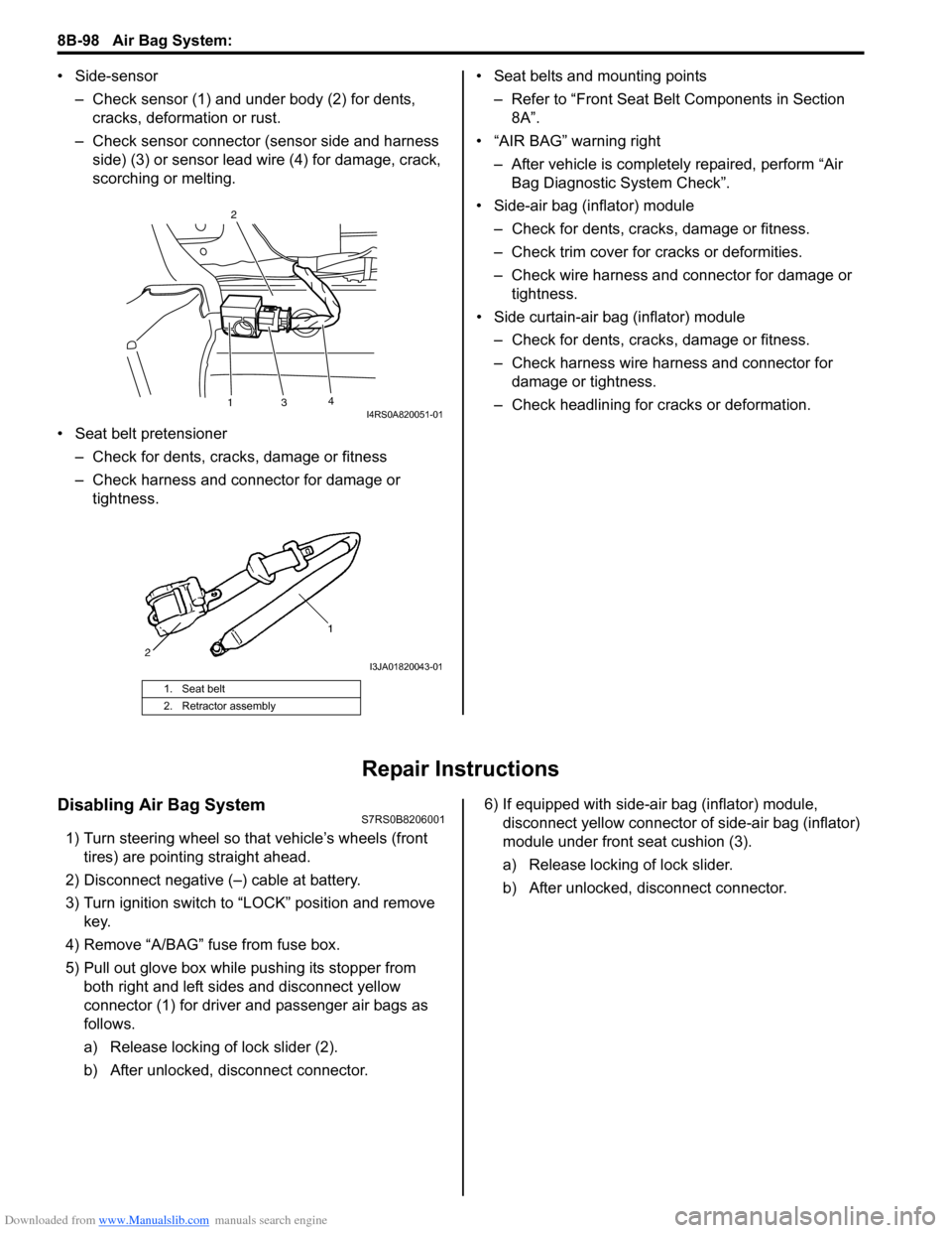
• Side-sensor– Check sensor (1) and under body (2) for dents, cracks, deformation or rust.
– Check sensor connector (sensor side and harness side) (3) or sensor lead wire (4) for damage, crack,
scorching or melting.
• Seat belt pretensioner – Check for dents, cracks , damage or fitness
– Check harness and connector for damage or tightness. • Seat belts and mounting points
– Refer to “Front Seat Belt Components in Section 8A”.
• “AIR BAG” warning right
– After vehicle is completely repaired, perform “Air Bag Diagnostic System Check”.
• Side-air bag (inflator) module – Check for dents, cra cks, damage or fitness.
– Check trim cover for cracks or deformities.
– Check wire harness and connector for damage or tightness.
• Side curtain-air bag (inflator) module – Check for dents, cra cks, damage or fitness.
– Check harness wire harness and connector for damage or tightness.
– Check headlining for cracks or deformation.
Repair Instructions
Disabling Air Bag SystemS7RS0B8206001
1) Turn steering wheel so that vehicle’s wheels (front tires) are pointing straight ahead.
2) Disconnect negative (–) cable at battery.
3) Turn ignition switch to “LOCK” position and remove key.
4) Remove “A/BAG” fu se from fuse box.
5) Pull out glove box while pushing its stopper from
both right and left sides and disconnect yellow
connector (1) for driver and passenger air bags as
follows.
a) Release locking of lock slider (2).
b) After unlocked, disconnect connector. 6) If equipped with side-air bag (inflator) module,
disconnect yellow connector of side-air bag (inflator)
module under front seat cushion (3).
a) Release locking of lock slider.
b) After unlocked, disconnect connector.
1. Seat belt
2. Retractor assembly
13 4
2I4RS0A820051-01
I3JA01820043-01
Page 1151 of 1496
Downloaded from www.Manualslib.com manuals search engine Air Bag System: 8B-113
Air Bag (Inflator) Module and Seat Belt
Pretensioner Disposal
S7RS0B8206018
WARNING!
Failure to follow proper air bag (inflator)
module and seat belt pretensioner disposal
procedures can result in air bag deployment
and pretensioner activation which may cause
personal injury. Do not dispose of live
(undeployed) air bag (inflator) modules and
seat belt pretensioners. Because undeployed
air bag (inflator) module / inactivated seat
belt pretensioner must not be disposed of
through normal refuse channels. Undeployed
air bag (inflator) module and inactivated seat
belt pretensioner contain substances that
can cause severe illness or personal injury if
sealed container is damaged during disposal.
Air bag (inflator) module / seat belt pretensioner can be
deployed / activated inside or outside of vehicle.
Deployment / Activation method used depends upon
final disposition of vehicle. Review the following
instructions in order to deter mine which will work best in
a given situation.
Deployment / Activation Ou tside of Vehicle: When you
intend to return the vehicle to service, deploy the air bag
(inflator) module(s) and/or activate seat belt
pretensioner(s) outside of the vehicle.
Deployment / Activation Insi de of Vehicle: When the
vehicle will be destroyed, or salvaged for component
parts, deploy the air bag module(s) and/or activate seat
belt pretensioner(s) installed on vehicle.
WARNING!
The following precautions must be observed
for this work. Failure to observe any of them
may result in personal injury.
• Procedure should be followed strictly as described here.
• Be sure to read “Precautions on Service and Diagnosis of Air Bag System”
beforehand.
• To avoid accidental deployment / activation, this work should be performed
by no more than one person.
• Since smoke is produced when air bag (inflator) module is deployed and
pretensioner is activated, select well-
ventilated area.
• Air bag (inflator) module and seat belt pretensioner will immediately deploy /
activate when 12 volts vehicle battery is
connected to it. Wear safety glasses
throughout this entire deployment /
activation and disposal procedure.
• Wear suitable ear protection when deploying air bag (inflator) module /
activating seat belt pretensioner. Also,
advise those who are in area close to
deployment / activation site to wear
suitable ear protection.
• Do not deploy / activate two or more air bag system components (air bag (inflator)
modules and seat belt pretensioners) at
the same time.
• Never connect deployment harness to any 12 volts vehicle battery before connecting
deployment harness to air bag (inflator)
module and seat belt pretensioner.
Deployment harness sh all remain shorted
and not be connected to 12 volts vehicle
battery till you are ready to deploy air bag
(inflator) module or activate seat belt
pretensioner.
Page 1155 of 1496
Downloaded from www.Manualslib.com manuals search engine Air Bag System: 8B-117
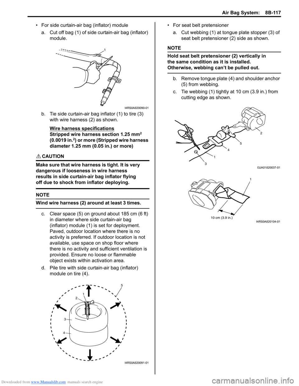
• For side curtain-air bag (inflator) modulea. Cut off bag (1) of side curtain-air bag (inflator) module.
b. Tie side curtain-air bag inflator (1) to tire (3) with wire harness (2) as shown.
Wire harness specifications
Stripped wire harness section 1.25 mm2
(0.0019 in.2) or more (Stripped wire harness
diameter 1.25 mm (0.05 in.) or more)
CAUTION!
Make sure that wire harness is tight. It is very
dangerous if looseness in wire harness
results in side curtain-air bag inflator flying
off due to shock from inflator deploying.
NOTE
Wind wire harness (2) around at least 3 times.
c. Clear space (5) on ground about 185 cm (6 ft) in diameter where side curtain-air bag
(inflator) module (1) is set for deployment.
Paved, outdoor location where there is no
activity is preferred. If outdoor location is not
available, use space on shop floor where
there is no activity and sufficient ventilation is
provided. Ensure no loose or flammable
object exists within activation area.
d. Pile tire with side curtain-air bag (inflator) module on tire (4). • For seat belt pretensioner
a. Cut webbing (1) at tongue plate stopper (3) of seat belt pretensioner (2) side as shown.
NOTE
Hold seat belt pretensioner (2) vertically in
the same condition as it is installed.
Otherwise, webbing can’t be pulled out.
b. Remove tongue plate (4) and shoulder anchor (5) from webbing.
c. Tie webbing (1) tightly at 10 cm (3.9 in.) from
cutting edge as shown.
1
I4RS0A820090-01
1
2
3
4
5
I4RS0A820091-01
3 1 4
5 2I3JA01820037-01
10 cm (3.9 in.)
1
I4RS0A820104-01
Page 1156 of 1496
Downloaded from www.Manualslib.com manuals search engine 8B-118 Air Bag System:
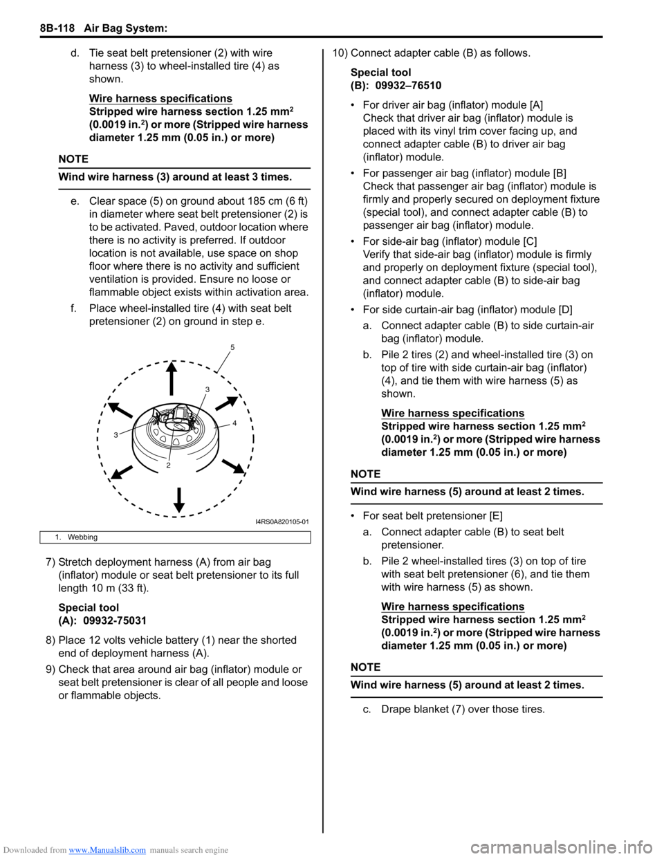
d. Tie seat belt pretensioner (2) with wire harness (3) to wheel-installed tire (4) as
shown.
Wire harness specifications
Stripped wire harness section 1.25 mm2
(0.0019 in.2) or more (Stripped wire harness
diameter 1.25 mm (0.05 in.) or more)
NOTE
Wind wire harness (3) around at least 3 times.
e. Clear space (5) on ground about 185 cm (6 ft) in diameter where seat belt pretensioner (2) is
to be activated. Paved, outdoor location where
there is no activity is preferred. If outdoor
location is not available, use space on shop
floor where there is no activity and sufficient
ventilation is provided. Ensure no loose or
flammable object exists within activation area.
f. Place wheel-installed tire (4) with seat belt pretensioner (2) on ground in step e.
7) Stretch deployment harness (A) from air bag (inflator) module or seat belt pretensioner to its full
length 10 m (33 ft).
Special tool
(A): 09932-75031
8) Place 12 volts vehicle battery (1) near the shorted end of deployment harness (A).
9) Check that area around air bag (inflator) module or seat belt pretensioner is clear of all people and loose
or flammable objects. 10) Connect adapter cable (B) as follows.
Special tool
(B): 09932–76510
• For driver air bag (inflator) module [A]Check that driver air bag (inflator) module is
placed with its vinyl trim cover facing up, and
connect adapter cable (B) to driver air bag
(inflator) module.
• For passenger air bag (inflator) module [B] Check that passenger air bag (inflator) module is
firmly and properly secured on deployment fixture
(special tool), and connect adapter cable (B) to
passenger air bag (inflator) module.
• For side-air bag (inflator) module [C] Verify that side-air bag (inflator) module is firmly
and properly on deployment fixture (special tool),
and connect adapter cable (B) to side-air bag
(inflator) module.
• For side curtain-air bag (inflator) module [D] a. Connect adapter cable (B) to side curtain-air bag (inflator) module.
b. Pile 2 tires (2) and wheel-installed tire (3) on top of tire with side curtain-air bag (inflator)
(4), and tie them with wire harness (5) as
shown.
Wire harness specifications
Stripped wire harness section 1.25 mm2
(0.0019 in.2) or more (Stripped wire harness
diameter 1.25 mm (0.05 in.) or more)
NOTE
Wind wire harness (5) around at least 2 times.
• For seat belt pretensioner [E]
a. Connect adapter cable (B) to seat belt pretensioner.
b. Pile 2 wheel-installed tires (3) on top of tire with seat belt pretensioner (6), and tie them
with wire harness (5) as shown.
Wire harness specifications
Stripped wire harness section 1.25 mm2
(0.0019 in.2) or more (Stripped wire harness
diameter 1.25 mm (0.05 in.) or more)
NOTE
Wind wire harness (5) around at least 2 times.
c. Drape blanket (7) over those tires.
1. Webbing
4
3
3 2 5
I4RS0A820105-01
Page 1161 of 1496
Downloaded from www.Manualslib.com manuals search engine Air Bag System: 8B-123
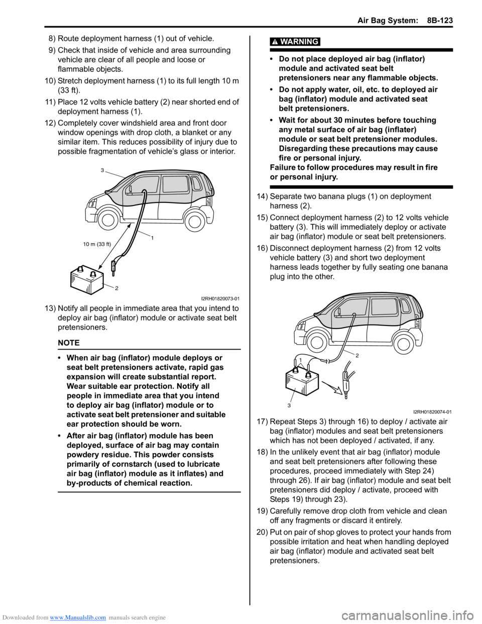
8) Route deployment harness (1) out of vehicle.
9) Check that inside of vehicle and area surrounding vehicle are clear of all people and loose or
flammable objects.
10) Stretch deployment harness (1) to its full length 10 m (33 ft).
11) Place 12 volts vehicle battery (2) near shorted end of deployment harness (1).
12) Completely cover windshield area and front door window openings with drop cloth, a blanket or any
similar item. This reduces possibility of injury due to
possible fragmentation of vehicle’s glass or interior.
13) Notify all people in immediate area that you intend to deploy air bag (inflator) module or activate seat belt
pretensioners.
NOTE
• When air bag (inflator) module deploys or seat belt pretensioners activate, rapid gas
expansion will create substantial report.
Wear suitable ear protection. Notify all
people in immediate area that you intend
to deploy air bag (inflator) module or to
activate seat belt pretensioner and suitable
ear protection should be worn.
• After air bag (inflator) module has been deployed, surface of air bag may contain
powdery residue. This powder consists
primarily of cornstarch (used to lubricate
air bag (inflator) module as it inflates) and
by-products of chemical reaction.
WARNING!
• Do not place deployed air bag (inflator) module and activated seat belt
pretensioners near any flammable objects.
• Do not apply water, oil, etc. to deployed air bag (inflator) module and activated seat
belt pretensioners.
• Wait for about 30 minutes before touching any metal surface of air bag (inflater)
module or seat belt pretensioner modules.
Disregarding these precautions may cause
fire or personal injury.
Failure to follow procedures may result in fire
or personal injury.
14) Separate two banana plugs (1) on deployment harness (2).
15) Connect deployment harness (2) to 12 volts vehicle battery (3). This will immedi ately deploy or activate
air bag (inflator) module or seat belt pretensioners.
16) Disconnect deployment harness (2) from 12 volts vehicle battery (3) and short two deployment
harness leads together by fully seating one banana
plug into the other.
17) Repeat Steps 3) through 16) to deploy / activate air bag (inflator) modules and seat belt pretensioners
which has not been deployed / activated, if any.
18) In the unlikely event that air bag (inflator) module and seat belt pretensioners after following these
procedures, proceed immediately with Step 24)
through 26). If air bag (inflator) module and seat belt
pretensioners did deploy / activate, proceed with
Steps 19) through 23).
19) Carefully remove drop cloth from vehicle and clean off any fragments or discard it entirely.
20) Put on pair of shop gloves to protect your hands from
possible irritation and heat when handling deployed
air bag (inflator) module and activated seat belt
pretensioners.
10 m (33 ft) 1
2
3
I2RH01820073-01
1
3 2
I2RH01820074-01
Page 1288 of 1496
Downloaded from www.Manualslib.com manuals search engine 9B-6 Lighting Systems:
Headlight Bulb ReplacementS7RS0B9206002
WARNING!
• To avoid danger of being burned, don’t touch when the bulb is hot.
• Don’t touch glass surface of bulb, to avoid deteriorate as the case may be unclear
when bulb light on at dirty condition.
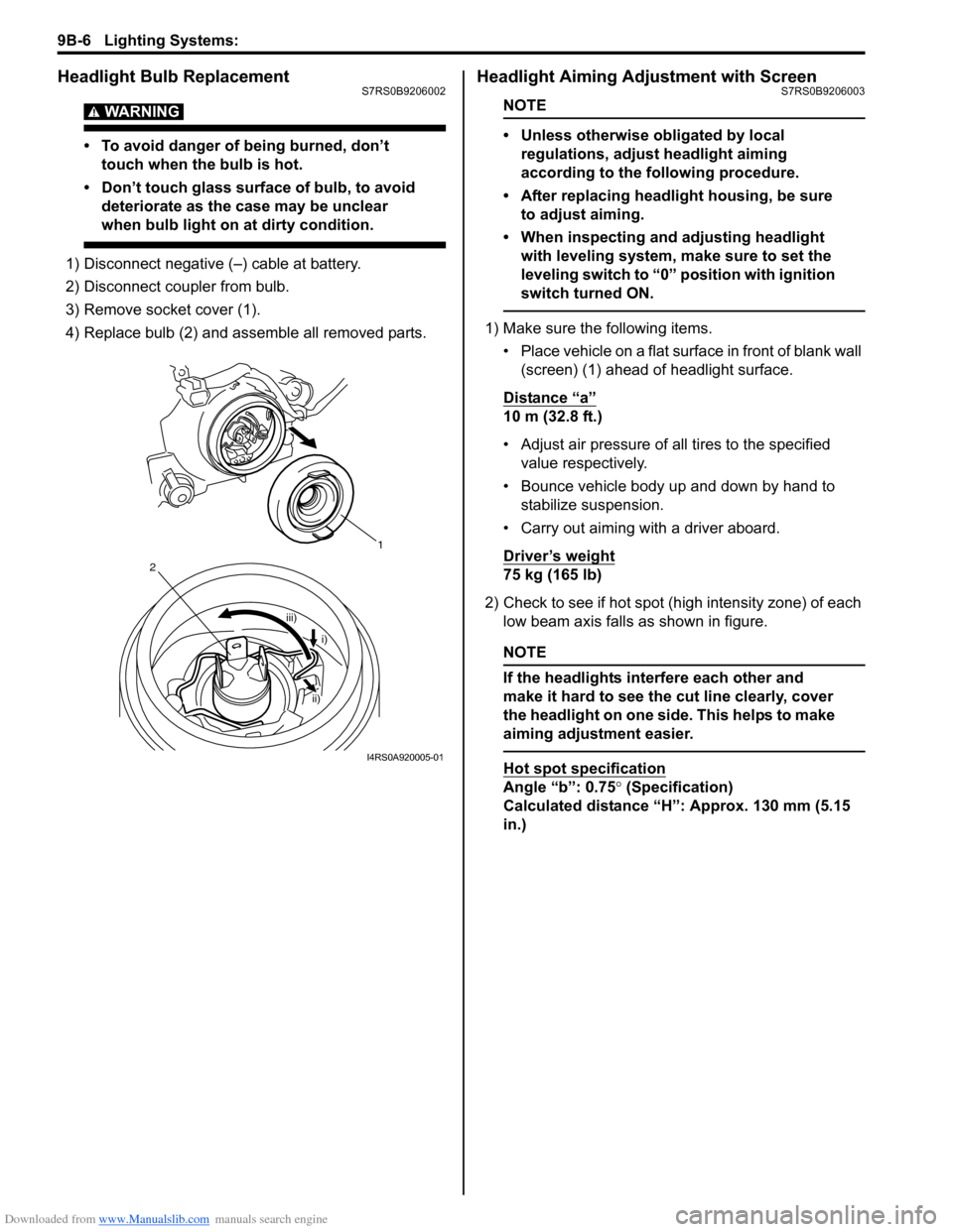
1) Disconnect negative (–) cable at battery.
2) Disconnect coupler from bulb.
3) Remove socket cover (1).
4) Replace bulb (2) and assemble all removed parts.
Headlight Aiming Adjustment with ScreenS7RS0B9206003
NOTE
• Unless otherwise obligated by local regulations, adjust headlight aiming
according to the following procedure.
• After replacing headlight housing, be sure to adjust aiming.
• When inspecting and adjusting headlight with leveling system, make sure to set the
leveling switch to “0 ” position with ignition
switch turned ON.
1) Make sure the following items.
• Place vehicle on a flat surface in front of blank wall (screen) (1) ahead of headlight surface.
Distance “a”
10 m (32.8 ft.)
• Adjust air pressure of all tires to the specified value respectively.
• Bounce vehicle body up and down by hand to stabilize suspension.
• Carry out aiming with a driver aboard.
Driver’s weight
75 kg (165 lb)
2) Check to see if hot spot (high intensity zone) of each low beam axis falls as shown in figure.
NOTE
If the headlights interfere each other and
make it hard to see the cut line clearly, cover
the headlight on one side. This helps to make
aiming adjustment easier.
Hot spot specification
Angle “b”: 0.75 ° (Specification)
Calculated distance “H”: Approx. 130 mm (5.15
in.)
1
iii)
2
i)
ii)
I4RS0A920005-01