2008 SUZUKI SWIFT wiper blade
[x] Cancel search: wiper bladePage 437 of 1496
Downloaded from www.Manualslib.com manuals search engine Front Suspension: 2B-4
Reference Information
Side slip
When checked with side slip tester, side slip should
satisfy following specification.Side slip
0 to IN 3.0 mm/m (0 to IN 0.118 in/3.3 ft)
If side slip is greatly di
fferent, toe or front wheel
alignment may not be correct.
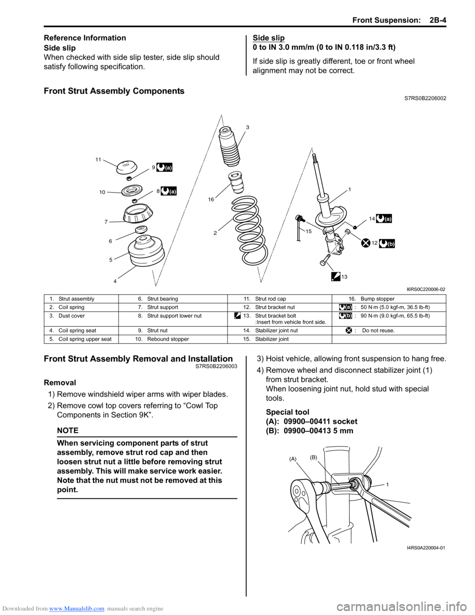
Front Strut Assembly ComponentsS7RS0B2206002
Front Strut Assembly Removal and InstallationS7RS0B2206003
Removal
1) Remove windshield wipe r arms with wiper blades.
2) Remove cowl top covers referring to “Cowl Top
Components in Section 9K”.
NOTE
When servicing component parts of strut
assembly, remove stru t rod cap and then
loosen strut nut a little before removing strut
assembly. This will make service work easier.
Note that the nut must not be removed at this
point.
3) Hoist vehicle, allowing front suspension to hang free.
4) Remove wheel and disconn ect stabilizer joint (1)
from strut bracket.
When loosening joint nu t, hold stud with special
tools.
Special tool
(A): 09900–00411 socket
(B): 09900–00413 5 mm
11 3
2 1
12
13
4
5
6
7
10
8(a)
(b)
9
(a)
14
15(a)
16
I6RS0C220006-02
1. Strut assembly
6. Strut bearing 11. Strut rod cap16. Bump stopper
2. Coil spring 7. Strut support 12. Strut bracket nut : 50 N⋅m (5.0 kgf-m, 36.5 lb-ft)
3. Dust cover 8. Strut support lower nut 13. Strut bracket bolt
:Insert from vehicle front side. : 90 N
⋅m (9.0 kgf-m, 65.5 lb-ft)
4. Coil spring seat 9. Strut nut 14. Stabilizer joint nut : Do not reuse.
5. Coil spring upper seat 10. Rebound stopper 15. Stabilizer joint
1
(A)
(B)
I4RS0A220004-01
Page 438 of 1496
Downloaded from www.Manualslib.com manuals search engine 2B-5 Front Suspension:
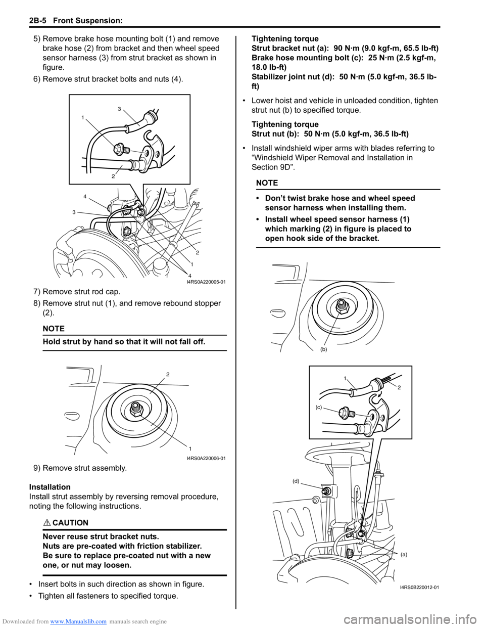
5) Remove brake hose mounting bolt (1) and remove brake hose (2) from bracket and then wheel speed
sensor harness (3) from strut bracket as shown in
figure.
6) Remove strut bracket bolts and nuts (4).
7) Remove strut rod cap.
8) Remove strut nut (1), and remove rebound stopper (2).
NOTE
Hold strut by hand so th at it will not fall off.
9) Remove strut assembly.
Installation
Install strut assembly by reversing removal procedure,
noting the following instructions.
CAUTION!
Never reuse strut bracket nuts.
Nuts are pre-coated with friction stabilizer.
Be sure to replace pre-coated nut with a new
one, or nut may loosen.
• Insert bolts in such direction as shown in figure.
• Tighten all fasteners to specified torque. Tightening torque
Strut bracket nut (a): 90 N·m (9.0 kgf-m, 65.5 lb-ft)
Brake hose mounting bolt (c): 25 N·m (2.5 kgf-m,
18.0 lb-ft)
Stabilizer joint nut (d): 50 N·m (5.0 kgf-m, 36.5 lb-
ft)
• Lower hoist and vehicle in unloaded condition, tighten strut nut (b) to specified torque.
Tightening torque
Strut nut (b): 50 N·m (5.0 kgf-m, 36.5 lb-ft)
• Install windshield wiper arms with blades referring to
“Windshield Wiper Removal and Installation in
Section 9D”.
NOTE
• Don’t twist brake hose and wheel speed sensor harness when installing them.
• Install wheel speed sensor harness (1) which marking (2) in figure is placed to
open hook side of the bracket.
1 3
2
2
1
4
4
3
I4RS0A220005-01
2
1
I4RS0A220006-01
(d) (a)
(b)
(c)
1
2
I4RS0B220012-01
Page 1320 of 1496
Downloaded from www.Manualslib.com manuals search engine 9D-3 Wipers / Washers:
Washer Tank and Washer Pump Removal and
Installation
S7RS0B9406002
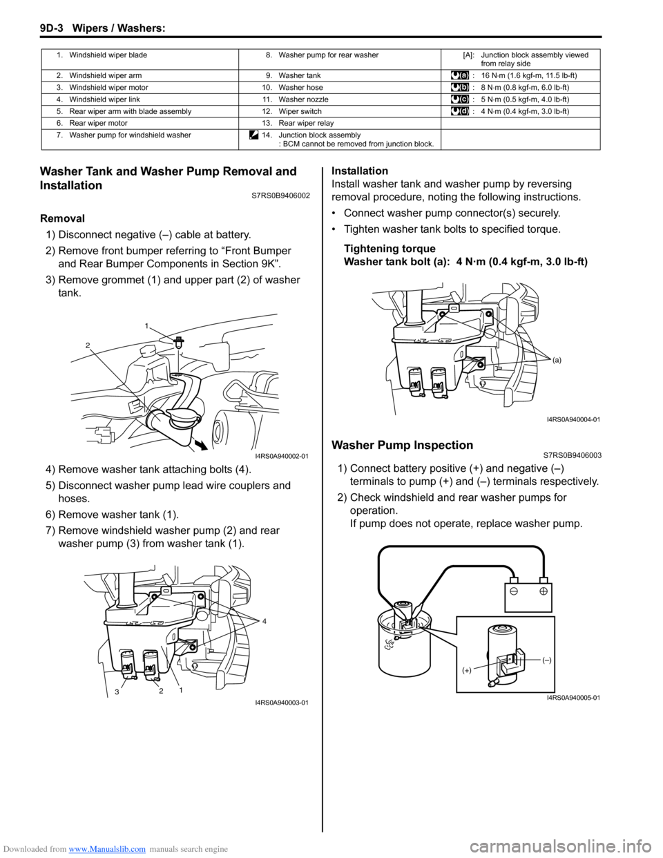
Removal1) Disconnect negative (–) cable at battery.
2) Remove front bumper referring to “Front Bumper and Rear Bumper Components in Section 9K”.
3) Remove grommet (1) and upper part (2) of washer tank.
4) Remove washer tank attaching bolts (4).
5) Disconnect washer pump lead wire couplers and hoses.
6) Remove washer tank (1).
7) Remove windshield washer pump (2) and rear washer pump (3) from washer tank (1). Installation
Install washer tank and washer pump by reversing
removal procedure, noting the following instructions.
• Connect washer pump connector(s) securely.
• Tighten washer tank bolts to specified torque.
Tightening torque
Washer tank bolt (a): 4 N·m (0.4 kgf-m, 3.0 lb-ft)
Washer Pump InspectionS7RS0B9406003
1) Connect battery positive (+) and negative (–) terminals to pump (+) and (–) terminals respectively.
2) Check windshield and rear washer pumps for
operation.
If pump does not operate, replace washer pump.
1. Windshield wiper blade 8. Washer pump for rear washer[A]: Junction block assembly viewed
from relay side
2. Windshield wiper arm 9. Washer tank: 16 N⋅m (1.6 kgf-m, 11.5 lb-ft)
3. Windshield wiper motor 10. Washer hose : 8 N⋅m (0.8 kgf-m, 6.0 lb-ft)
4. Windshield wiper link 11. Washer nozzle : 5 N⋅m (0.5 kgf-m, 4.0 lb-ft)
5. Rear wiper arm with blade assembly 12. Wiper switch : 4 N⋅m (0.4 kgf-m, 3.0 lb-ft)
6. Rear wiper motor 13. Rear wiper relay
7. Washer pump for windshield washer 14. Junction block assembly
: BCM cannot be removed from junction block.
1
2
I4RS0A940002-01
2 1 4
3
I4RS0A940003-01
(a)
I4RS0A940004-01
(–)
(+)
I4RS0A940005-01
Page 1321 of 1496
Downloaded from www.Manualslib.com manuals search engine Wipers / Washers: 9D-4
Windshield Wiper Removal and InstallationS7RS0B9406004
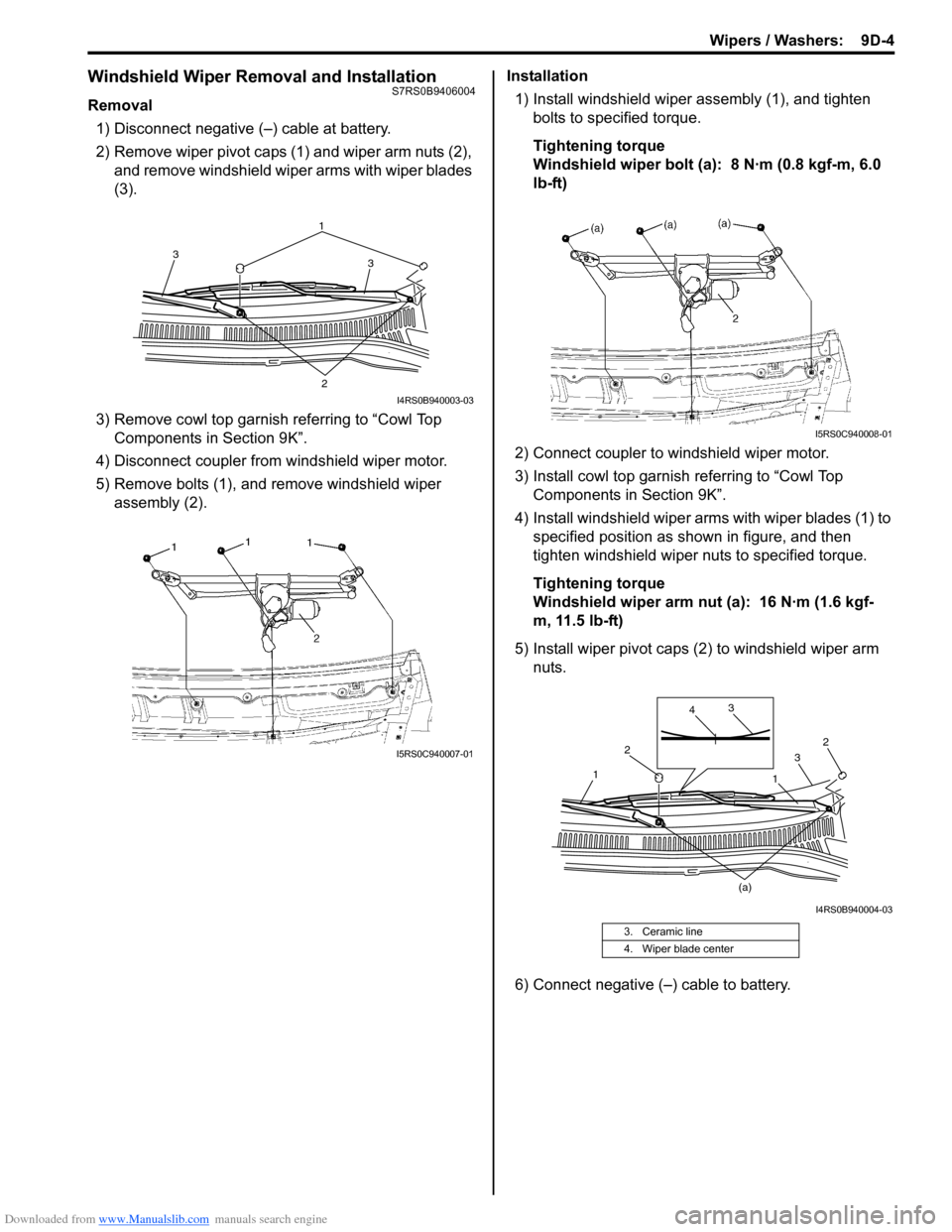
Removal1) Disconnect negative (–) cable at battery.
2) Remove wiper pivot caps (1) and wiper arm nuts (2), and remove windshield wiper arms with wiper blades
(3).
3) Remove cowl top garnish referring to “Cowl Top Components in Section 9K”.
4) Disconnect coupler from windshield wiper motor.
5) Remove bolts (1), and remove windshield wiper assembly (2). Installation
1) Install windshield wiper assembly (1), and tighten bolts to specified torque.
Tightening torque
Windshield wiper bolt (a): 8 N·m (0.8 kgf-m, 6.0
lb-ft)
2) Connect coupler to windshield wiper motor.
3) Install cowl top garnish referring to “Cowl Top
Components in Section 9K”.
4) Install windshield wiper arms with wiper blades (1) to specified position as shown in figure, and then
tighten windshield wiper nuts to specified torque.
Tightening torque
Windshield wiper arm nut (a): 16 N·m (1.6 kgf-
m, 11.5 lb-ft)
5) Install wiper pivot caps (2 ) to windshield wiper arm
nuts.
6) Connect negative (–) cable to battery.
1 3
3
2
I4RS0B940003-03
I5RS0C940007-01
3. Ceramic line
4. Wiper blade center
I5RS0C940008-01
2
2 3
3
4
1
1
(a)
I4RS0B940004-03
Page 1322 of 1496
Downloaded from www.Manualslib.com manuals search engine 9D-5 Wipers / Washers:
Windshield Wiper Motor InspectionS7RS0B9406005
NOTE
Make sure that battery voltage is 12 V or
more.
1) Disconnect negative (–) cable at battery.
2) Remove windshield wiper arms with wiper blades
referring to “Windshield Wiper Removal and
Installation”.
3) Remove cowl top garnish referring to “Cowl Top Components in Section 9K”.
4) Disconnect coupler from windshield wiper motor.
5) Reinstall windshield wiper arms with wiper blade. For
details, refer to Step 4) of “Installation” in “Windshield
Wiper Removal and Installation”.
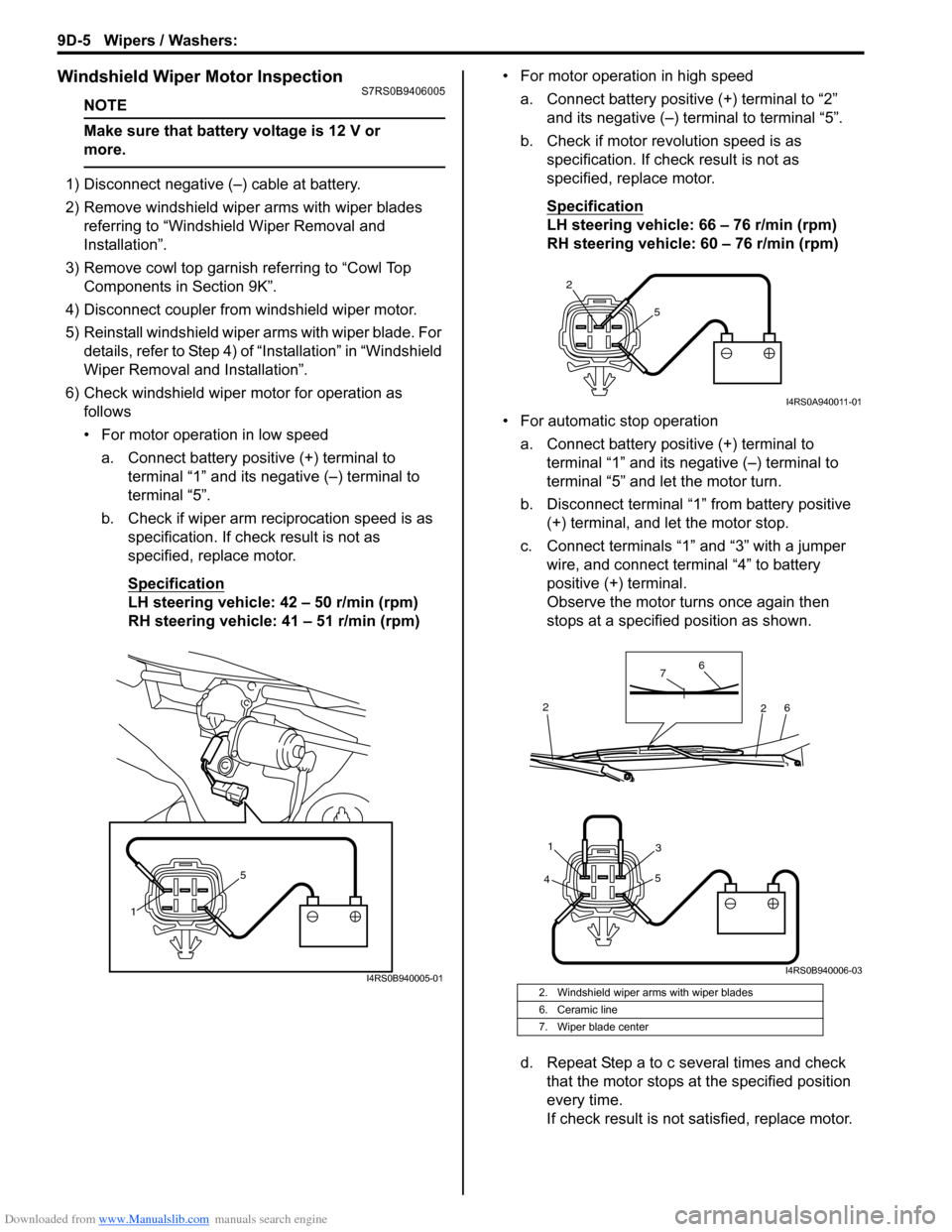
6) Check windshield wiper motor for operation as
follows
• For motor operation in low speed
a. Connect battery positive (+) terminal to terminal “1” and its negative (–) terminal to
terminal “5”.
b. Check if wiper arm reciprocation speed is as specification. If check result is not as
specified, replace motor.
Specification
LH steering vehicle: 42 – 50 r/min (rpm)
RH steering vehicle: 41 – 51 r/min (rpm) • For motor operation in high speed
a. Connect battery positive (+) terminal to “2” and its negative (–) terminal to terminal “5”.
b. Check if motor revolution speed is as specification. If chec k result is not as
specified, replace motor.
Specification
LH steering vehicle: 66 – 76 r/min (rpm)
RH steering vehicle: 60 – 76 r/min (rpm)
• For automatic stop operation a. Connect battery positive (+) terminal to terminal “1” and its negative (–) terminal to
terminal “5” and let the motor turn.
b. Disconnect terminal “1” from battery positive (+) terminal, and let the motor stop.
c. Connect terminals “1” and “3” with a jumper wire, and connect terminal “4” to battery
positive (+) terminal.
Observe the motor turns once again then
stops at a specified position as shown.
d. Repeat Step a to c several times and check that the motor stops at the specified position
every time.
If check result is not satisfied, replace motor.
1 5
I4RS0B940005-012. Windshield wiper arms with wiper blades
6. Ceramic line
7. Wiper blade center
2
5
I4RS0A940011-01
4 5
31
6
6
7
2
2
I4RS0B940006-03
Page 1323 of 1496
Downloaded from www.Manualslib.com manuals search engine Wipers / Washers: 9D-6
Rear Wiper Removal and InstallationS7RS0B9406006
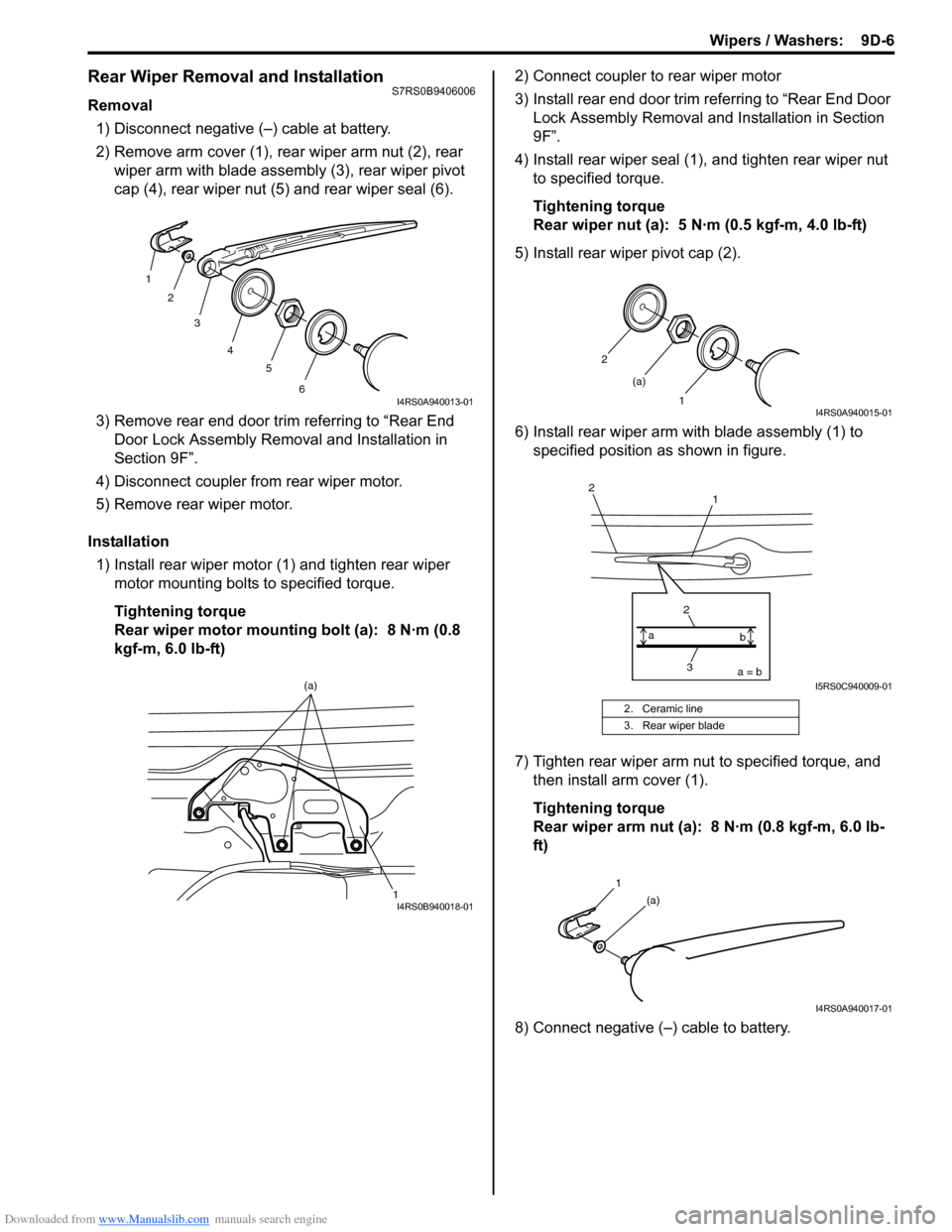
Removal1) Disconnect negative (–) cable at battery.
2) Remove arm cover (1), rear wiper arm nut (2), rear wiper arm with blade assembly (3), rear wiper pivot
cap (4), rear wiper nut (5) and rear wiper seal (6).
3) Remove rear end door trim referring to “Rear End Door Lock Assembly Remo val and Installation in
Section 9F”.
4) Disconnect coupler from rear wiper motor.
5) Remove rear wiper motor.
Installation 1) Install rear wiper motor (1) and tighten rear wiper motor mounting bolts to specified torque.
Tightening torque
Rear wiper motor mounting bolt (a): 8 N·m (0.8
kgf-m, 6.0 lb-ft) 2) Connect coupler to rear wiper motor
3) Install rear end door trim referring to “Rear End Door
Lock Assembly Removal and Installation in Section
9F”.
4) Install rear wiper seal (1), and tighten rear wiper nut to specified torque.
Tightening torque
Rear wiper nut (a): 5 N·m (0.5 kgf-m, 4.0 lb-ft)
5) Install rear wiper pivot cap (2).
6) Install rear wiper arm with blade assembly (1) to specified position as shown in figure.
7) Tighten rear wiper arm nut to specified torque, and then install arm cover (1).
Tightening torque
Rear wiper arm nut (a): 8 N·m (0.8 kgf-m, 6.0 lb-
ft)
8) Connect negative (–) cable to battery.
1 2
3
4 5
6
I4RS0A940013-01
1
(a)I4RS0B940018-01
2. Ceramic line
3. Rear wiper blade
2
1
(a)
I4RS0A940015-01
1
2
3
2a = b
a
bI5RS0C940009-01
1
(a)
I4RS0A940017-01