2008 SUZUKI SWIFT control device
[x] Cancel search: control devicePage 449 of 1496
Downloaded from www.Manualslib.com manuals search engine Front Suspension: 2B-16
4) Hoist vehicle and remove both wheels referring to “Wheel Removal and Installation in Section 2D”.
5) Remove cotter pins and tie-rod end nuts, and then disconnect both tie-rod ends from steering knuckles
referring to “Tie-Rod End Re moval and Installation in
Section 6C”.
6) Disconnect couplers of torque sensor and P/S motor.
7) Remove suspension control arm referring to “Suspension Control Arm / Bushing Removal and
Installation”.
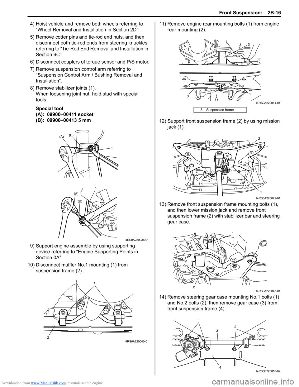
8) Remove stabilizer joints (1). When loosening joint nu t, hold stud with special
tools.
Special tool
(A): 09900–00411 socket
(B): 09900–00413 5 mm
9) Support engine assemble by using supporting device referring to “Engine Supporting Points in
Section 0A”.
10) Disconnect muffler No.1 mounting (1) from suspension frame (2). 11) Remove engine rear mounting bolts (1) from engine
rear mounting (2).
12) Support front suspension frame (2) by using mission jack (1).
13) Remove front suspension frame mounting bolts (1), and then lower mission jack and remove front
suspension frame (2) with st abilizer bar and steering
gear case.
14) Remove steering gear case mounting No.1 bolts (1) and No.2 bolts (2), then remove gear case (3) from
front suspensio n frame (4).
11
(A)
(A)
(B)
(B)
I4RS0A220038-01
1
2
I4RS0A220040-01
3. Suspension frame
2
3 1
I4RS0A220041-01
2
1
I4RS0A220042-01
1
2 1
I4RS0A220043-01
1
3
4 2
I4RS0B220010-02
Page 570 of 1496
Downloaded from www.Manualslib.com manuals search engine 4E-31 ABS:
2) Bleed air from brake system referring to “Air Bleeding of Brake System in Section 4A”.
3) Check each installed part for fluid leakage and perform “ABS Hydraulic Un it Operation Check”.
NOTE
For new ABS hydraulic unit / control module
assembly, if “ABS Hydraulic Unit Operation
Check” has not been performed, ABS
warning light may flash when ignition switch
is turned ON position.
Accordingly preform “ABS Hydraulic Unit
Operation Check” to stop flashing of ABS
warning light.
Front / Rear Wheel Speed Sensor On-Vehicle
Inspection
S7RS0B4506005
Output Voltage Inspection
1) Disconnect negative cable from battery.
2) Hoist vehicle a little.
3) Disconnect wheel speed sensor connector.
4) Disconnect wheel speed grommet from vehicle body.
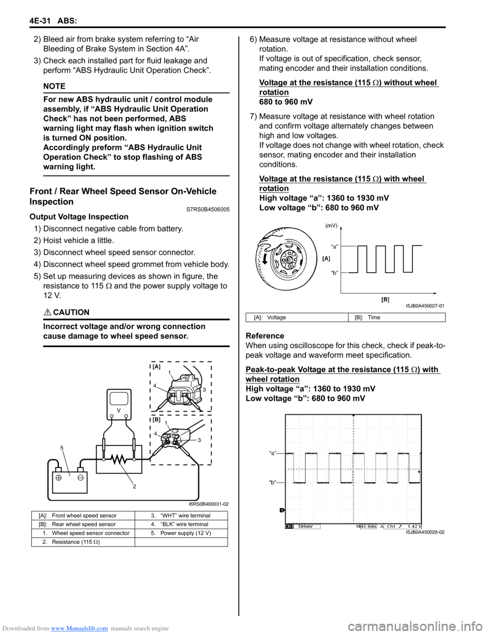
5) Set up measuring devices as shown in figure, the resistance to 115 Ω and the power supply voltage to
12 V.
CAUTION!
Incorrect voltage and/or wrong connection
cause damage to wheel speed sensor.
6) Measure voltage at resistance without wheel rotation.
If voltage is out of specification, check sensor,
mating encoder and their installation conditions.
Voltage at the resistance (115
Ω) without wheel
rotation
680 to 960 mV
7) Measure voltage at resistance with wheel rotation and confirm voltage alternately changes between
high and low voltages.
If voltage does not change with wheel rotation, check
sensor, mating encoder and their installation
conditions.
Voltage at the resistance (115
Ω) with wheel
rotation
High voltage “a”: 1360 to 1930 mV
Low voltage “b”: 680 to 960 mV
Reference
When using oscilloscope for this check, check if peak-to-
peak voltage and waveform meet specification.
Peak-to-peak Voltage at the resistance (115
Ω) with
wheel rotation
High voltage “a”: 1360 to 1930 mV
Low voltage “b”: 680 to 960 mV
[A]: Front wheel speed sensor 3. “WHT” wire terminal
[B]: Rear wheel speed sensor 4. “BLK” wire terminal
1. Wheel speed sensor connector 5. Power supply (12 V)
2. Resistance (115 Ω )
V
2
5
41
3
43
1
[A]
[B]
I6RS0B460031-02
[A]: Voltage [B]: Time
I5JB0A450027-01
I5JB0A450028-02
Page 631 of 1496

Downloaded from www.Manualslib.com manuals search engine Electronic Stability Program: 4F-57
3) Remove front brake pipe referring to “Front Brake Hose / Pipe Removal and In stallation in Section 4A”.
4) Remove ESP ® hydraulic unit / control module with
bracket from vehicle by removing bracket bolts.
5) Remove bolt (4) and pull out ESP ® hydraulic unit /
control module assembly (1) from bracket (3) using
flat end rod or the like (2).
Installation 1) Install hydraulic unit / co ntrol module assembly and
by reversing removal procedure.
Tightening torque
Brake pipe flare nut: 16 N·m (1.6 kgf-m, 11.5 lb-
ft)
ESP ® hydraulic unit / control module assembly
bolt: 9 N·m (0.9 kgf-m, 6.5 lb-ft)
ESP ® hydraulic unit / control module assembly
bracket bolt: 25 N·m (2.5 kgf-m, 18.0 lb-ft)
2) Bleed air from brake system referring to “Air Bleeding of Brake System in Section 4A”.
3) Check each installed part for fluid leakage.
4) Connect SUZUKI Scan Tool.
5) Turn ignition switch to ON position. And SLIP indicator lamp flush. (Other than replace with new
one) If other than SLIP indicator lamp light, check
DTC and repair it.
6) Turn ignition switch to ON position. And ESP®
warning lamp, SLIP indicator lamp, ESP ® OFF
lamp, Brake warning lamp lights and ABS warning
lamp flush. (Replace new one)
7) Check DTC.
NOTE
If any DTC(s) other than C1075, C1076 or
C1078 are detected, sensor calibration can
not be completed. Repair the detected it(s)
first.
8) Perform “Sensor Calibration”.
9) Perform “ESP ® Hydraulic Unit Operation Check”.
10) Turn ignition switch to OFF position once and then
ON position. In this state, make sure that indicator
light and warning light turns off.
11) Check DTC(s) are not stored in hydraulic unit / control module.
Front / Rear Wheel Speed Sensor On-Vehicle
Inspection
S7RS0B4606028
CAUTION!
Incorrect voltage and/or wrong connection
cause damage to wheel speed sensor.
Output Voltage Inspection
1) Disconnect negative (–) cable from battery.
2) Hoist vehicle a little.
3) Disconnect wheel speed sensor connector.
4) Disconnect wheel speed grommet from vehicle body.
5) Set up measuring devices as shown in figure, the resistance to 115 Ω and the power supply voltage
to12 V.
4
1
2 3
I6RS0B460030-02
[A]: Front wheel speed sensor 3. “WHT” wire terminal
[B]: Rear wheel speed sensor 4. “BLK” wire terminal
1. Wheel speed sensor connector 5. Power supply (12 V)
2. Resistance (115 Ω)
V
2
5
4 1
3
43
1
[A]
[B]
I6RS0B460031-02
Page 647 of 1496
Downloaded from www.Manualslib.com manuals search engine Automatic Transmission/Transaxle: 5A-3
General Description
A/T DescriptionS7RS0B5101001
This automatic transaxle is electronic control full automatic transaxle with forward 4-speed and reverse 1-speed.
The torque converter is a 3-element, 1-step and 2-phase type and is equipped with an automatically controlled lock-up
mechanism.
The gear change device consists of a ravigneau type planet ary gear unit, 3 multiple disc type clutches, 3 multiple disc
type brakes and 2 one-way clutches.
The hydraulic pressure control device consists of a valve body assembly, pressure control solenoid valve (linear
solenoid), 2 shift solenoid va lves, TCC pressure control solenoid valve (lin ear solenoid) and a timing solenoid valve.
Optimum line pressure complying with engine torque is produced by the pressure control solenoid valve in
dependence upon control signal from transmission control module (TCM). This makes it possible to control the line
pressure with high accuracy in accordance with the engine power and running conditions to achieve smooth shifting
characteristics and high efficiency.
A clutch-to-clutch control system is prov ided for shifting between 3rd gear and 4th gear. This clutch-to-clutch control
system is made to function optimally , so that hydraulic pressure controls such as shown below are conducted.
• When upshifting from 3rd gear to 4th gear, to adjust the drain hydraulic pressure at releasing the forward clutch, a
timing solenoid valve is used to switch a hydraulic passage with an orifice to another during shifting.
• When downshifting from 4th gear to 3rd gear, to adjust the line pressure applied to the forward clutch at engaging the forward clutch, a timing solenoid valve is used to s witch a hydraulic passage with an orifice to another during
shifting.
• When upshifting from 3rd gear to 4th gear with engine throttle opened, to optimize the line pressure applied to the forward clutch at releasing the forward clutch, the learning control is processed to compensate the switching timing
of the timing solenoid at every shifting.
• When downshifting from 4th gear to 3rd gear with engine throttle opened, to optimize the line pressure applied to
the forward clutch at engaging the forw ard clutch, the learning control is processed to compensate the line pressure
at every shifting.
Employing the ravigneau type planetary gear unit and this clutch-to-clutch control system greatly simplifies the
construction to make possible a lightweight and compact transaxle.
A line pressure learning control is conducted to provide opti mum shifting time at every upshifting with engine throttle
opened. If long upshifting time is detected, the subsequent line pressure applied during upshifting is intensified. On the
contrary, if short upshifting time is detected, the subs equent line pressure applied during upshifting is weakened.
Slip controlled lock-up function
Even at a lower speed than when the TCC gets engaged completely, control over the TCC pressure control solenoid
works to cause the TCC to slip (be engaged slightly), ther eby improving the transmission efficiency. While such slip
control is being executed, the oil pressure applied to the TCC is controlled by the TCC pressure control solenoid so
that the difference between the engine speed and the input shaft speed becomes close to the specified value.
Also, during deceleration, the TCC is made to slip (be enga ged slightly) to raise the engine speed and enlarge the fuel
cut operation range so that better fuel consumption is achieved.
Due to this reason, it is absolutely necessary for the automati c transmission to use ATF suitable for slip control. Use of
any fluid other than the specified ATF may cause j uddering or some other faulty condition to occur.
Page 649 of 1496
Downloaded from www.Manualslib.com manuals search engine Automatic Transmission/Transaxle: 5A-5
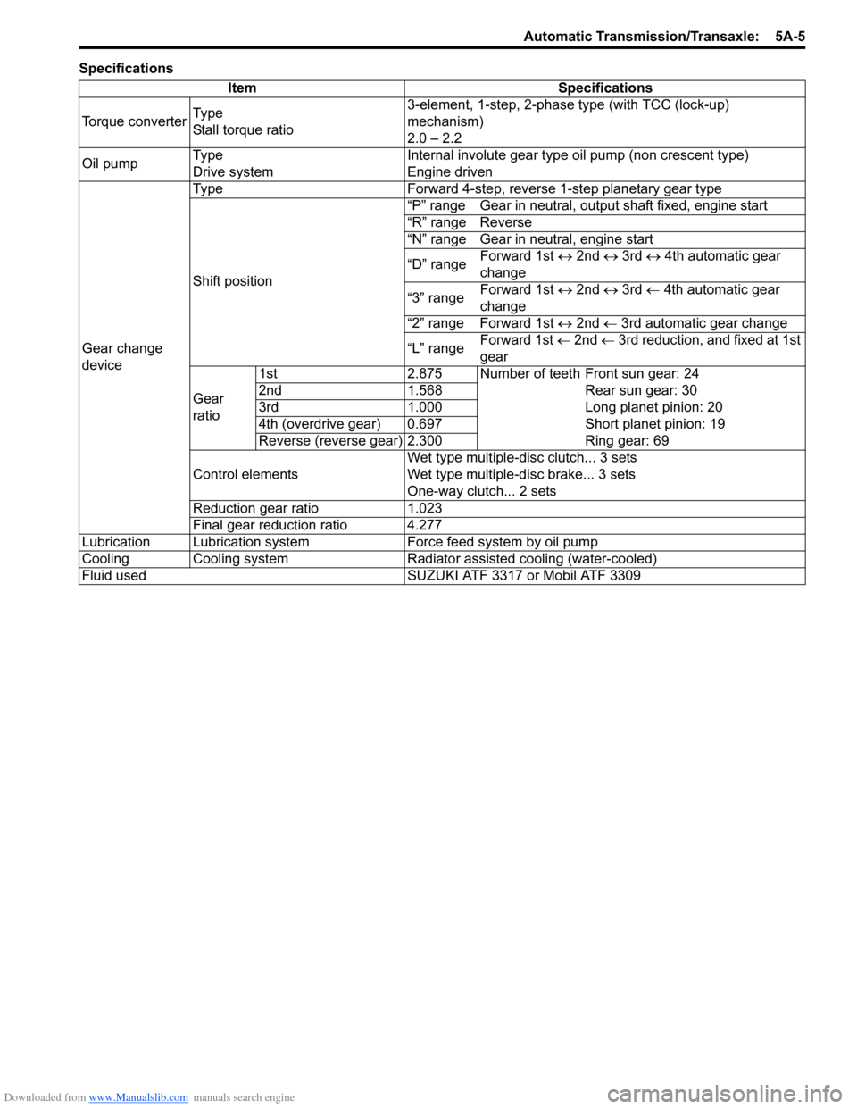
SpecificationsItem Specifications
Torque converter Ty p e
Stall torque ratio 3-element, 1-step, 2-phase type (with TCC (lock-up)
mechanism)
2.0 – 2.2
Oil pump Ty p e
Drive system Internal involute gear type oil pump (non crescent type)
Engine driven
Gear change
device Type Forward 4-step, reverse 1-step planetary gear type
Shift position
“P” range Gear in neutral, output shaft fixed, engine start
“R” range Reverse
“N” range Gear in neutral, engine start
“D” range
Forward 1st
↔ 2nd ↔ 3rd ↔ 4th automatic gear
change
“3” range Forward 1st
↔ 2nd ↔ 3rd ← 4th automatic gear
change
“2” range Forward 1st ↔ 2nd ← 3rd automatic gear change
“L” range Forward 1st
← 2nd ← 3rd reduction, and fixed at 1st
gear
Gear
ratio 1st 2.875 Number of teeth Front sun gear: 24
2nd 1.568 Rear sun gear: 30
3rd 1.000 Long planet pinion: 20
4th (overdrive gear) 0.697 Short planet pinion: 19
Reverse (reverse gear) 2.300 Ring gear: 69
Control elements Wet type multiple-disc clutch... 3 sets
Wet type multiple-d
isc brake... 3 sets
One-way clutch... 2 sets
Reduction gear ratio 1.023
Final gear reduction ratio 4.277
Lubrication Lubrication system Force feed system by oil pump
Cooling Cooling system Radiator assisted cooling (water-cooled)
Fluid used SUZUKI ATF 3317 or Mobil ATF 3309
Page 823 of 1496

Downloaded from www.Manualslib.com manuals search engine Manual Transmission/Transaxle: 5B-9
Manual Transaxle Unit Dismounting and
Remounting
S7RS0B5206009
Dismounting1) Drain coolant and transaxle oil.
2) Remove coolant reservoir with reservoir hose.
3) Remove battery and tray.
4) Remove air cleaner case and resonator.
5) Disconnect gear shift and gear select control cables (1) while pressing claws (2) of clip (3).
6) Disconnect back up light switch coupler and undo wiring harness clamps.
7) Remove ground cable from transaxle.
8) Remove clutch operating cylinder with fluid hose from transaxle.
9) Remove water inlet No.2 pipe from transaxle.
10) Remove starting motor re ferring to “Starting Motor
Dismounting and Remounting in Section 1I”.
11) Remove transaxle to engine bolts (1) of upper side. 12) Support engine using supporting device (1).
CAUTION!
Do not apply supporting device to projection
part A. If do so, it may be deformed.
13) Remove front drive shafts and center shaft referring
to “Front Drive Shaft Assembly Removal and
Installation in Section 3A”.
14) Remove exhaust No.2 pipe referring to “Exhaust Pipe and Muffler Removal a nd Installation in Section
1K”.
15) Remove clutch housing lower plate (1).
1
2
3
I7RS0A521003-01
1
1
I4RS0A520018-01
1
A
I4RS0A520019-01
1I4RS0A520020-01
Page 1406 of 1496
Downloaded from www.Manualslib.com manuals search engine 10B-3 Body Electrical Control System:
Theft Deterrent LightS7RS0BA201003
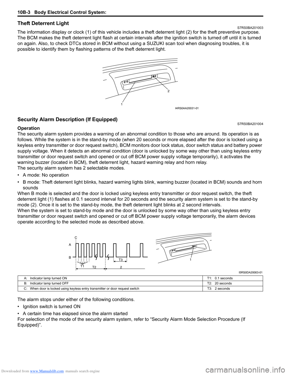
The information display or clock (1) of this vehicle includes a theft deterrent light (2) for the theft preventive purpose.
The BCM makes the theft deterrent light flash at certain interval s after the ignition switch is turned off until it is turned
on again. Also, to check DTCs stored in BCM without usin g a SUZUKI scan tool when diagnosing troubles, it is
possible to identify them by flashing patterns of the theft deterrent light.
Security Alarm Description (If Equipped)S7RS0BA201004
Operation
The security alarm system provides a warning of an abnormal condition to those who are around. Its operation is as
follows. While the system is in the stand- by mode (when 20 seconds or more elapsed after the door is locked using a
keyless entry transmitter or door request switch), BCM monitors door lock status, door switch status and battery power
supply voltage. When it detects an abnormal condition (door is unlocked by some way other than using keyless entry
transmitter or door request switch and opened or cut off BCM power supply voltage temporarily), it activates the
warning buzzer (located in BCM), theft deterr ent light, hazard warning relay and horn relay.
The security alarm system has 2 selectable modes.
• A mode: No operation
• B mode: Theft deterrent light blinks, hazard warning lights blink, warning buzzer (located in BCM) sounds and horn
sounds
When B mode is selected and the door is locked using keyl ess entry transmitter or door request switch, the theft
deterrent light (1) flashes at 0.1 second interval for 20 seconds and the se curity alarm system is set to the stand-by
mode (2). Once it is se t to the stand-by mode, the theft deterrent light blinks at 2 second intervals.
When the system is set to stand-by mode and the door is unlocked by some way other than using keyless entry
transmitter or door request switch and opened or cut off BCM power supply voltage temporarily, the alarm devices
operate according to the selected mode as described above.
The alarm stops under either of the following conditions.
• Ignition switch is turned ON
• A certain time has elapsed since the alarm started
For selection of the mode of the security alarm system , refer to “Security Alarm Mode Selection Procedure (If
Equipped)”.
1 2I4RS0AA20031-01
B A1T3
T1
T2 2
C
I5RS0DA20003-01
A: Indicator lamp turned ON
T1: 0.1 seconds
B: Indicator lamp turned OFF T2: 20 seconds
C: When door is locked using keyless entry tr ansmitter or door request switch T3: 2 seconds
Page 1445 of 1496
Downloaded from www.Manualslib.com manuals search engine Immobilizer Control System: 10C-2
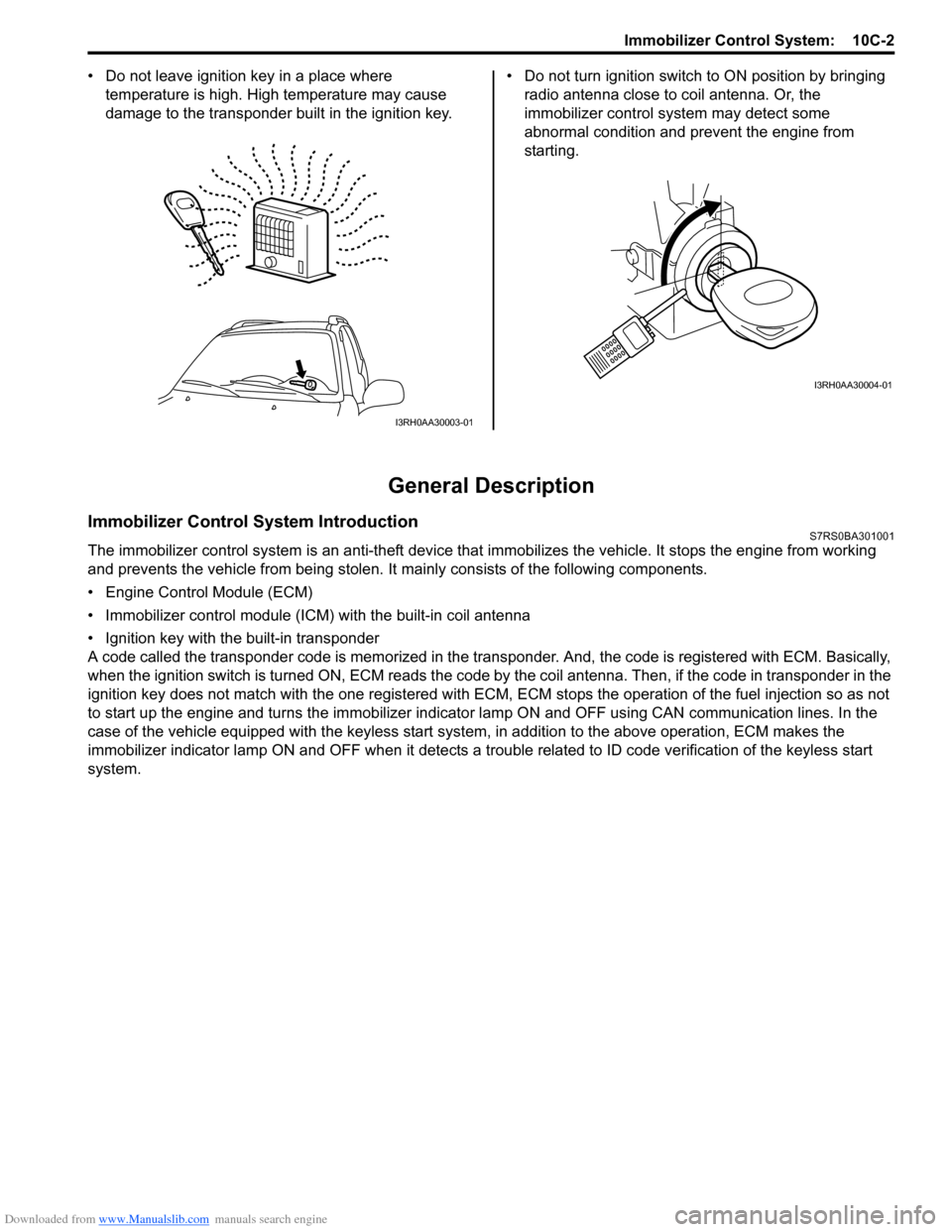
• Do not leave ignition key in a place where
temperature is high. High temperature may cause
damage to the transponder built in the ignition key. • Do not turn ignition switch to ON position by bringing
radio antenna close to coil antenna. Or, the
immobilizer control syst em may detect some
abnormal condition and prevent the engine from
starting.
General Description
Immobilizer Control System IntroductionS7RS0BA301001
The immobilizer control system is an anti-theft device that immobilizes the vehicle. It stops the engine from working
and prevents the vehicle from being stolen. It mainly consists of the following components.
• Engine Control Module (ECM)
• Immobilizer control module (ICM) with the built-in coil antenna
• Ignition key with the built-in transponder
A code called the transponder code is memorized in the tran sponder. And, the code is registered with ECM. Basically,
when the ignition switch is turned ON, ECM reads the code by the coil antenna. Then, if the code in transponder in the
ignition key does not match with the one registered with ECM, ECM stops the operati on of the fuel injection so as not
to start up the engine and turns the immobilizer indi cator lamp ON and OFF using CA N communication lines. In the
case of the vehicle equipped with the keyless start system , in addition to the above operation, ECM makes the
immobilizer indicator lamp ON and OFF when it detects a trouble related to ID code verification of the keyless start
system.
I3RH0AA30003-01
I3RH0AA30004-01