Page 843 of 1496

Downloaded from www.Manualslib.com manuals search engine Manual Transmission/Transaxle: 5B-29
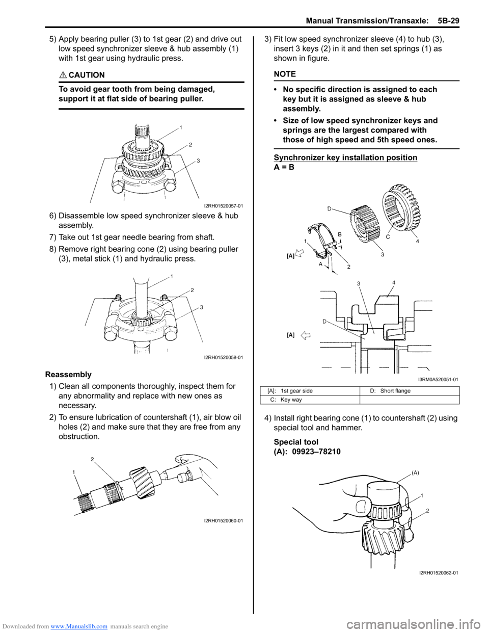
5) Apply bearing puller (3) to 1st gear (2) and drive out low speed synchronizer sleeve & hub assembly (1)
with 1st gear using hydraulic press.
CAUTION!
To avoid gear tooth from being damaged,
support it at flat side of bearing puller.
6) Disassemble low speed synchronizer sleeve & hub assembly.
7) Take out 1st gear needle bearing from shaft.
8) Remove right bearing cone (2) using bearing puller (3), metal stick (1) and hydraulic press.
Reassembly 1) Clean all components thor oughly, inspect them for
any abnormality and replace with new ones as
necessary.
2) To ensure lubrication of countershaft (1), air blow oil holes (2) and make sure that they are free from any
obstruction. 3) Fit low speed synchronizer sleeve (4) to hub (3),
insert 3 keys (2) in it and then set springs (1) as
shown in figure.
NOTE
• No specific direction is assigned to each key but it is assigned as sleeve & hub
assembly.
• Size of low speed synchronizer keys and springs are the largest compared with
those of high speed and 5th speed ones.
Synchronizer key installation position
A = B
4) Install right bearing cone (1) to countershaft (2) using special tool and hammer.
Special tool
(A): 09923–78210
I2RH01520057-01
I2RH01520058-01
I2RH01520060-01
[A]: 1st gear side D: Short flange
C: Key way
I3RM0A520051-01
I2RH01520062-01
Page 924 of 1496

Downloaded from www.Manualslib.com manuals search engine 6C-42 Power Assisted Steering System:
2) Connect tie-rod end to knuckle. Tighten tie-rod end nut (1) to spec ified torque.
3) Bend new split pin (2).
NOTE
After tightening tie-rod end nut to specified
torque, match next first slot of nut with hole
of tie-rod end for insertion of split pin
(rotation angle 60 ° max).
Tightening torque
Tie-rod end nut (a): 45 N·m (4.5 kgf-m, 32.5 lb-ft)
4) Inspect for proper toe re ferring to “Front Wheel
Alignment Inspection and Adjustment in Section 2B”.
5) After confirming proper toe, tighten tie-rod end lock nut to specified torque.
Tightening torque
Tie-rod end lock nut (a): 45 N·m (4.5 kgf-m, 32.5
lb-ft)
6) Tighten wheel nuts to specified torque and lower hoist.
Tightening torque
Wheel nut: 85 N·m (8.5 kgf-m, 61.5 lb-ft)
Tie-Rod End InspectionS7RS0B6306004
• Inspect for play in ball joint.
• Inspect for play in rack end ball joint. In either case, if found defective, replace.
Steering Shaft Joint On-Vehicle InspectionS7RS0B6306005
Check shaft joint for wear, breakage and any other
damage and replace if any defect exists.
Steering Gear Case Assembly Removal and
Installation
S7RS0B6306006
Removal
CAUTION!
Be sure to set front wheels (tires) in straight
direction and remove ignition key from key
cylinder before performing the following
steps; otherwise, contact coil of air bag
system may get damaged.
1) Remove front suspension frame with steering gear case assembly referrin g to “Front Suspension
Frame, Stabilizer Bar and/ or Bushings Removal and
Installation in Section 2B”.
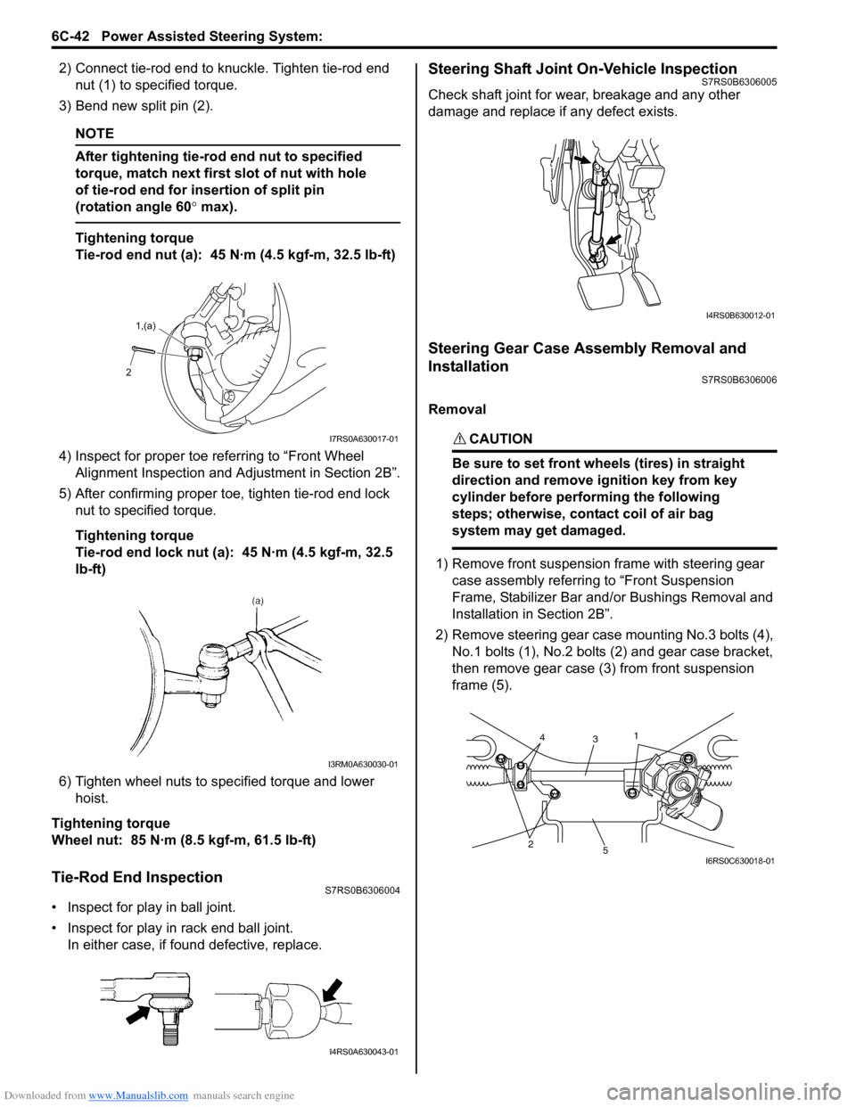
2) Remove steering gear case mounting No.3 bolts (4), No.1 bolts (1), No.2 bolts (2) and gear case bracket,
then remove gear case (3) from front suspension
frame (5).
2 1,(a)
I7RS0A630017-01
I3RM0A630030-01
I4RS0A630043-01
I4RS0B630012-01
25
3
14
I6RS0C630018-01
Page 1310 of 1496

Downloaded from www.Manualslib.com manuals search engine 9C-15 Instrumentation / Driver Info. / Horn:
Combination Meter Removal and InstallationS7RS0B9306003
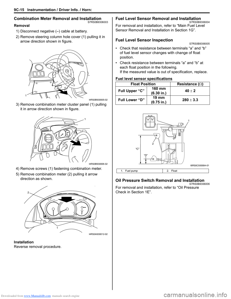
Removal1) Disconnect negative (–) cable at battery.
2) Remove steering column hole cover (1) pulling it in arrow direction shown in figure.
3) Remove combination mete r cluster panel (1) pulling
it in arrow direction shown in figure.
4) Remove screws (1) fast ening combination meter.
5) Remove combination me ter (2) pulling it arrow
direction as shown.
Installation
Reverse removal procedure.
Fuel Level Sensor Removal and InstallationS7RS0B9306004
For removal and installation, refer to “Main Fuel Level
Sensor Removal and Installation in Section 1G”.
Fuel Level Sensor InspectionS7RS0B9306005
• Check that resistance between terminals “a” and “b” of fuel level sensor changes with change of float
position.
• Check resistance between terminals “a” and “b” at each float position in the following.
If the measured value is out of specification, replace.
Fuel level sensor specifications
Oil Pressure Switch Removal and InstallationS7RS0B9306006
For removal and installation , refer to “Oil Pressure
Check in Section 1E”.
1
I4RS0B930005-02
1
I4RS0B930006-02
1
2
I4RS0A930012-02
Float Position Resistance (Ω)
Full Upper “C” 160 mm
(6.30 in.) 40
± 2
Full Lower “D” 19 mm
(0.75 in.) 280
± 3.3
1. Fuel pump 2. Float
“b”“a”
2
“C”
“D”
1
I6RS0C930004-01
Page 1342 of 1496

Downloaded from www.Manualslib.com manuals search engine 9E-15 Glass / Windows / Mirrors:
Rear End Door Window Defogger Wire
Inspection
S7RS0B9506014
NOTE
• When cleaning rear end door window glass, use a dry cloth to wipe it along heat
wire (1) direction.
• When cleaning glass, do not use detergent or abrasive-containing glass cleaner.
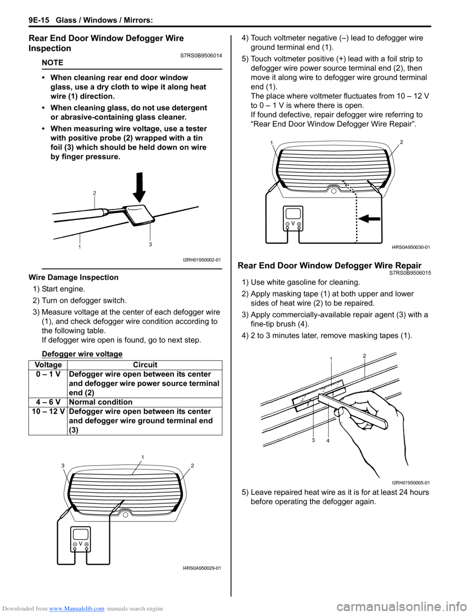
• When measuring wire voltage, use a tester with positive probe (2) wrapped with a tin
foil (3) which should be held down on wire
by finger pressure.
Wire Damage Inspection
1) Start engine.
2) Turn on defogger switch.
3) Measure voltage at the center of each defogger wire (1), and check defogger wire condition according to
the following table.
If defogger wire open is found, go to next step.
Defogger wire voltage
4) Touch voltmeter negative (–) lead to defogger wire ground terminal end (1).
5) Touch voltmeter positive (+) lead with a foil strip to defogger wire power source terminal end (2), then
move it along wire to defogger wire ground terminal
end (1).
The place where voltmeter fluctuates from 10 – 12 V
to 0 – 1 V is where there is open.
If found defective, repair defogger wire referring to
“Rear End Door Window Defogger Wire Repair”.
Rear End Door Window Defogger Wire RepairS7RS0B9506015
1) Use white gasoline for cleaning.
2) Apply masking tape (1) at both upper and lower sides of heat wire (2) to be repaired.
3) Apply commercially-available repair agent (3) with a fine-tip brush (4).
4) 2 to 3 minutes later, remove masking tapes (1).
5) Leave repaired heat wire as it is for at least 24 hours before operating the defogger again.
Voltage Circuit
0 – 1 V Defogger wire open between its center and defogger wire power source terminal
end (2)
4 – 6 V Normal condition
10 – 12 V Defogger wire open between its center and defogger wire ground terminal end
(3)
I2RH01950002-01
2
1
3
I4RS0A950029-01
21
I4RS0A950030-01
I2RH01950005-01
Page:
< prev 1-8 9-16 17-24