2008 SUZUKI SWIFT Oil direction
[x] Cancel search: Oil directionPage 460 of 1496
Downloaded from www.Manualslib.com manuals search engine 2C-6 Rear Suspension:
Spring Upper Seat and Lower Seat Removal and
Installation
S7RS0B2306007
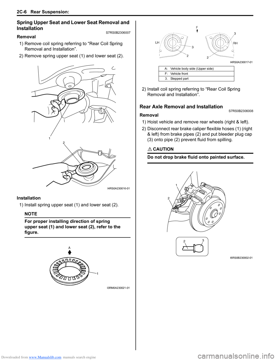
Removal1) Remove coil spring referring to “Rear Coil Spring Removal and Installation”.
2) Remove spring upper seat (1) and lower seat (2).
Installation 1) Install spring upper seat (1) and lower seat (2).
NOTE
For proper installing direction of spring
upper seat (1) and lower seat (2), refer to the
figure.
2) Install coil spring referr ing to “Rear Coil Spring
Removal and Installation”.
Rear Axle Removal and InstallationS7RS0B2306008
Removal
1) Hoist vehicle and remove rear wheels (right & left).
2) Disconnect rear brake caliper flexible hoses (1) (right & left) from brake pipes (2) and put bleeder plug cap
(3) onto pipe (2) prevent fluid from spilling.
CAUTION!
Do not drop brake fluid onto painted surface.
1
2
I4RS0A230016-01
I3RM0A230021-01
A: Vehicle body side (Upper side)
F: Vehicle front3. Stepped part
I4RS0A230017-01
1
2
2 3
I6RS0B230002-01
Page 492 of 1496
Downloaded from www.Manualslib.com manuals search engine 3A-14 Drive Shaft / Axle:
Center Shaft and Center Bearing Support
Disassembly and Reassembly
S7RS0B3106005
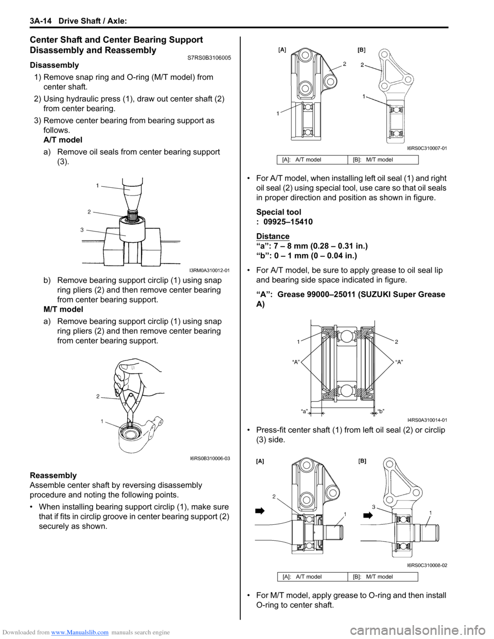
Disassembly1) Remove snap ring and O-ring (M/T model) from center shaft.
2) Using hydraulic press (1), draw out center shaft (2) from center bearing.
3) Remove center bearing from bearing support as follows.
A/T model
a) Remove oil seals from center bearing support (3).
b) Remove bearing support circlip (1) using snap ring pliers (2) and then remove center bearing
from center bearing support.
M/T model
a) Remove bearing support circlip (1) using snap ring pliers (2) and then remove center bearing
from center bearing support.
Reassembly
Assemble center shaft by reversing disassembly
procedure and noting the following points.
• When installing bearing support circlip (1), make sure
that if fits in circlip groove in center bearing support (2)
securely as shown. • For A/T model, when installing
left oil seal (1) and right
oil seal (2) using special tool, use care so that oil seals
in proper direction and position as shown in figure.
Special tool
: 09925–15410
Distance
“a”: 7 – 8 mm (0.28 – 0.31 in.)
“b”: 0 – 1 mm (0 – 0.04 in.)
• For A/T model, be sure to apply grease to oil seal lip and bearing side space indicated in figure.
“A”: Grease 99000–25011 (SUZUKI Super Grease
A)
• Press-fit center shaft (1) from left oil seal (2) or circlip
(3) side.
• For M/T model, apply grease to O-ring and then install O-ring to center shaft.
I3RM0A310012-01
I6RS0B310006-03
[A]: A/T model [B]: M/T model
[A]: A/T model [B]: M/T model
I6RS0C310007-01
12
“A” “A”
“a” “b”
I4RS0A310014-01
I6RS0C310008-02
Page 762 of 1496

Downloaded from www.Manualslib.com manuals search engine 5A-118 Automatic Transmission/Transaxle:
55) Remove one-way clutch outer race retainer (1).
56) Check one-way clutch No.2 as follows.• Ensure planetary carrier (1) rotates only in counterclockwise direction “A”, never in clockwise
direction “B”.
• If the planetary carrier rotates both ways or does not rotate either way, one-way clutch No.2
assembly will need to be replaced with new one-
way clutch No.2 assembly.
57) Remove one-way clutch No.2 assembly (1). 58) Remove planetary gear assembly (1).
59) Measure 1st and reverse brake piston stroke.
If piston stroke exce eds specified value,
disassemble, inspect and replace discs and plates.
• Using special tool, measure 1st and reserve brake piston stroke when compressed air (400 – 800
kPa, 4 – 8 kg/cm
2, 57 – 113 psi) is blown through
oil hole.
Special tool
(A): 09900–20607
(B): 09900–20701
(C): 09952–06020
1st and reverse brake piston stroke
Standard: 0.79 – 1.49 mm (0.031 – 0.059 in.)
I2RH0B510129-01
I2RH0B510130-01
1
I4RS0A510039-01
I2RH0B510132-01
I2RH0B510133-01
Page 776 of 1496

Downloaded from www.Manualslib.com manuals search engine 5A-132 Automatic Transmission/Transaxle:
• Measure forward clutch piston stroke in the same manner as “Forward and Reverse Clutch Assembly
Preliminary Check”.
When piston stroke is out of specification, select
forward clutch retaining plate with proper thickness
from among the following table and replace it.
Special tool
(A): 09900–20607
(B): 09900–20701
(C): 09952–06020
Forward clutch piston stroke
1.30 – 1.50 mm (0.051 – 0.059 in.)
Available forward clutch retaining plate thickness
• Install reverse clutch cushion plate (1) in correct direction as shown in figure.
• Apply A/T fluid to reverse clutch cushion plate (1),
reverse clutch separator plate (2), discs (3) and
retaining plate (4).
• Install reverse clutch cushio n plate (1), reverse clutch
separator plate (2), discs (3), retaining plate (4) and
then snap ring (5) to inte rmediate shaft subassembly. • Install reverse clutch plate snap ring so that its both
ends would be positioned in correct locations as
shown in figure.
• Measure reverse clutch piston stroke in the same manner as “Forward and Reverse Clutch Assembly
Preliminary Check”.
When piston stroke is out of specification, select
reverse clutch retaining plate with proper thickness
from among the following table and replace it.
Special tool
(A): 09900–20607
(B): 09900–20701
Reverse clutch piston stroke
1.20 – 1.60 mm (0.047 – 0.063 in.)
Available reverse clutch retaining plate thickness
Thickness Identification mark
3.0 mm (0.118 in.) 1
3.1 mm (0.122 in.) 5
3.2 mm (0.126 in.) 2
3.3 mm (0.130 in.) 6
3.4 mm (0.134 in.) 3
3.5 mm (0.138 in.) 7
3.6 mm (0.142 in.) 4
1. Oil hole
I2RH0B510177-02
I3RM0B510062-01
[A]: Correct[B]: Incorrect
ThicknessIdentification mark
3.0 mm (0.118 in.) 1
3.2 mm (0.126 in.) 2
3.4 mm (0.134 in.) 3
3.6 mm (0.142 in.) 4
I2RH0B510190-01
I2RH0B510191-01
Page 794 of 1496
Downloaded from www.Manualslib.com manuals search engine 5A-150 Automatic Transmission/Transaxle:
Automatic Transaxle Unit AssemblyS7RS0B5106060
CAUTION!
• Automatic transaxle consists of highly precise parts. As even flaw in small part
may cause oil leakage or decrease in
function, check each part carefully before
installation.
• Clean all parts with compressed air. Never use wiping cloths or rags.
• Before assembling new clutch or brake discs, soak them in automatic transaxle
fluid for at least 2 hours.
• Be sure to use new gaskets and O-rings.
• Lubricate O-rings with automatic transaxle
fluid.
• Apply automatic transaxle fluid on sliding or rotating surfaces of the parts before
assembly.
• Use Suzuki Super Grease “C” to retain parts in place.
• Be sure to install thrust bearings and races in correct direction and position.
• Make sure that snap ring ends are not aligned with one of cut outs and are
installed in groove correctly.
• Do not use adhesive cements on gaskets and similar parts.
• Be sure to torque each bolt and nut to specification.
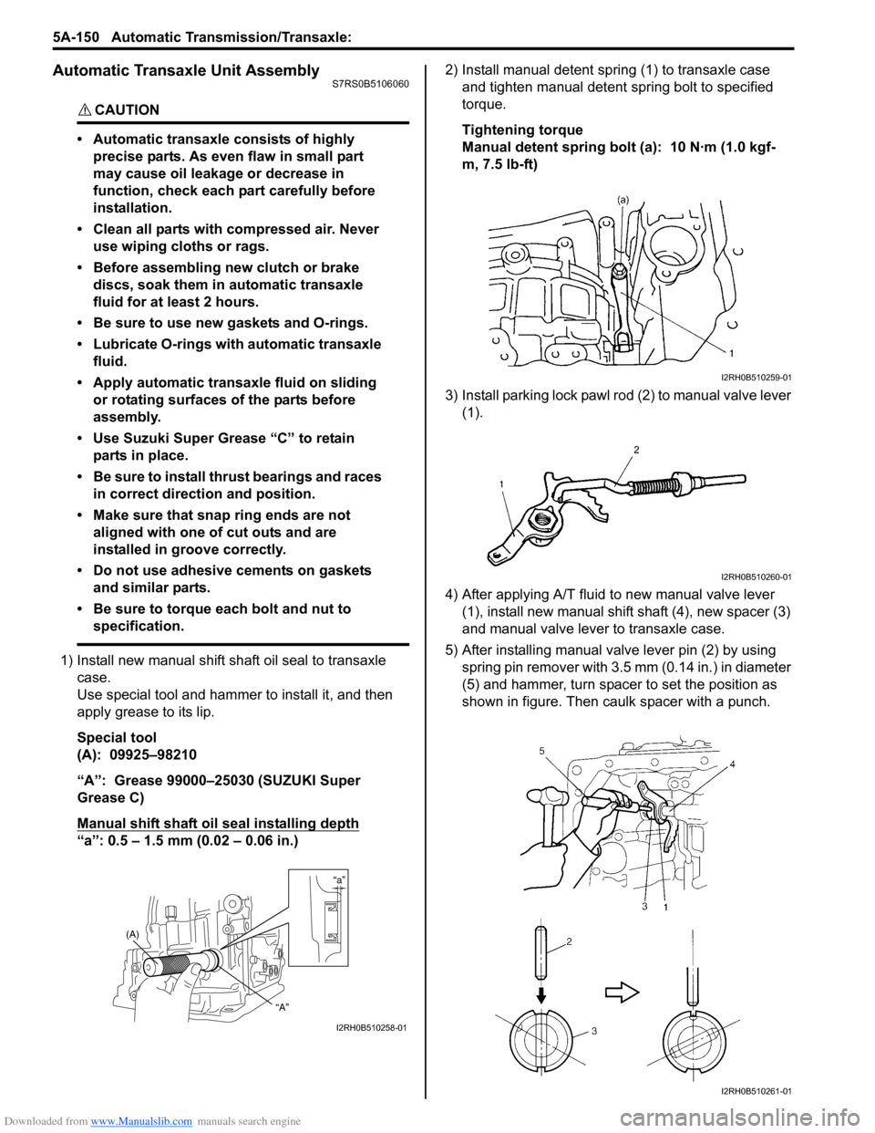
1) Install new manual shift sh aft oil seal to transaxle
case.
Use special tool and hammer to install it, and then
apply grease to its lip.
Special tool
(A): 09925–98210
“A”: Grease 99000–25030 (SUZUKI Super
Grease C)
Manual shift shaft oil seal installing depth
“a”: 0.5 – 1.5 mm (0.02 – 0.06 in.) 2) Install manual detent spring (1) to transaxle case
and tighten manual detent spring bolt to specified
torque.
Tightening torque
Manual detent spring bolt (a): 10 N·m (1.0 kgf-
m, 7.5 lb-ft)
3) Install parking lock pawl ro d (2) to manual valve lever
(1).
4) After applying A/T fluid to new manual valve lever (1), install new manual shift shaft (4), new spacer (3)
and manual valve lever to transaxle case.
5) After installing manual valve lever pin (2) by using spring pin remover with 3.5 mm (0.14 in.) in diameter
(5) and hammer, turn spacer to set the position as
shown in figure. Then caulk spacer with a punch.
“a”
(A)
“A”
I2RH0B510258-01
I2RH0B510259-01
I2RH0B510260-01
I2RH0B510261-01
Page 821 of 1496
Downloaded from www.Manualslib.com manuals search engine Manual Transmission/Transaxle: 5B-7
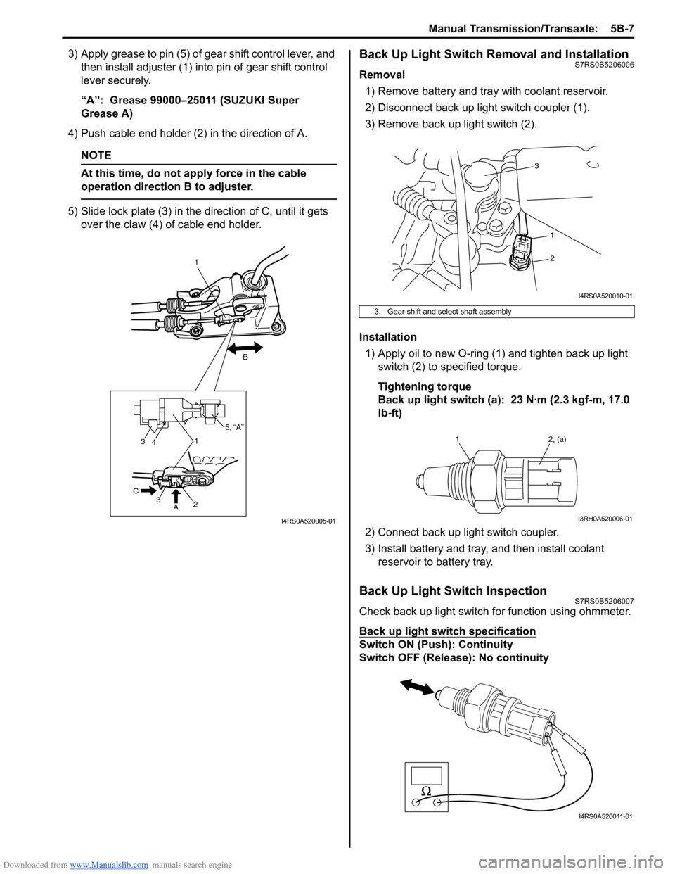
3) Apply grease to pin (5) of gear shift control lever, and then install adjuster (1) into pin of gear shift control
lever securely.
“A”: Grease 99000–25011 (SUZUKI Super
Grease A)
4) Push cable end holder (2) in the direction of A.
NOTE
At this time, do not a pply force in the cable
operation direction B to adjuster.
5) Slide lock plate (3) in the direction of C, until it gets over the claw (4) of cable end holder.
Back Up Light Switch Removal and InstallationS7RS0B5206006
Removal
1) Remove battery and tray with coolant reservoir.
2) Disconnect back up light switch coupler (1).
3) Remove back up light switch (2).
Installation 1) Apply oil to new O-ring (1) and tighten back up light switch (2) to specified torque.
Tightening torque
Back up light switch (a): 23 N·m (2.3 kgf-m, 17.0
lb-ft)
2) Connect back up light switch coupler.
3) Install battery and tray, and then install coolant reservoir to battery tray.
Back Up Light Switch InspectionS7RS0B5206007
Check back up light switch for function using ohmmeter.
Back up light switch specification
Switch ON (Push): Continuity
Switch OFF (Release ): No continuity
3
3
41
2
A
C
1
B
5, “A”
I4RS0A520005-01
3. Gear shift and select shaft assembly
3
1
2
I4RS0A520010-01
1 2, (a)
I3RH0A520006-01
I4RS0A520011-01
Page 829 of 1496

Downloaded from www.Manualslib.com manuals search engine Manual Transmission/Transaxle: 5B-15
Assembly1) Assemble 5th speed synchronizer sleeve (1), hub (2), 5th speed synchronizer levers (3) and
synchronizer ring (4) as follows.
a) Install hub (1) to 5th speed synchronizer sleeves (2) in specified direction as shown in figure.
b) Fit 5th speed synchronizer levers (1) to hub (2) as shown in figure.
NOTE
Align protrusion A of 5th speed synchronizer
levers (1) with groove of hub (2).
c) Install synchronizer ring (1) to hub (2) as shown in figure.
2) Install 5th gear (1) to countershaft facing machined boss A inward.
3) Install needle bearing to input shaft, apply oil then install input shaft 5th gear (1) and special tool to stop
shaft rotation.
Special tool
(A): 09927–76060
4) Tighten new countershaft nut (2) to specified torque, and caulk countershaft nut securely.
Tightening torque
Countershaft nut (a): 100 N·m (10.0 kgf-m, 72.5
lb-ft)
A: Chamfered side B: Long boss
I4RH01520054-01
1
2
B
A
I4RH01520048-01
1A
2
A
I4RH01520049-01
A: Machined boss (Inside)
B: No machining (Outside)
1
2
I4RH01520055-01
I2RH01520088-01
1
(A)
2, (a)
I3RM0B521016-01
Page 841 of 1496
Downloaded from www.Manualslib.com manuals search engine Manual Transmission/Transaxle: 5B-27
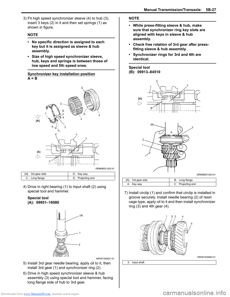
3) Fit high speed synchronizer sleeve (4) to hub (3), insert 3 keys (2) in it and then set springs (1) as
shown in figure.
NOTE
• No specific direction is assigned to each key but it is assigned as sleeve & hub
assembly.
• Size of high speed synchronizer sleeve, hub, keys and springs is between those of
low speed and 5th speed ones.
Synchronizer key in stallation position
A = B
4) Drive in right bearing (1) to input shaft (2) using special tool and hammer.
Special tool
(A): 09951–16080
5) Install 3rd gear needle bearing, apply oil to it, then install 3rd gear (1) and synchronizer ring (2).
6) Drive in high speed synchronizer sleeve & hub assembly (3) using special tool and hammer, facing
long flange side of hub to 3rd gear.
NOTE
• While press-fitting sleeve & hub, make sure that synchronizer ring key slots are
aligned with keys in sleeve & hub
assembly.
• Check free rotation of 3rd gear after press- fitting sleeve & hub assembly.
• Synchronizer rings for 3rd and 4th are identical.
Special tool
(B): 09913–84510
7) Install circlip (1) and confirm that circlip is installed in
groove securely. Install needle bearing (2) of resin
cage type, apply oil to it and then install synchronizer
ring (3) and 4th gear (4).
[A]: 3rd gear side D: Key way
C: Long flange E: Projecting end
I3RM0B521022-01
(A)
1
2
I4RH01520031-01
[A]: 3rd gear side B: Long flange
A: Key way C: Projecting end
5. Input shaft
I3RM0B521023-01
I2RH01520052-01